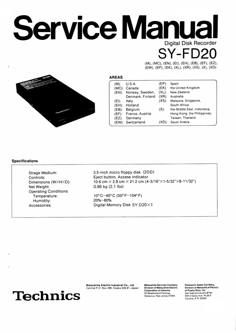
manuals.online logo
Brands
  1. Home
  2. •
  3. Brands
  4. •
  5. Technics
  6. •
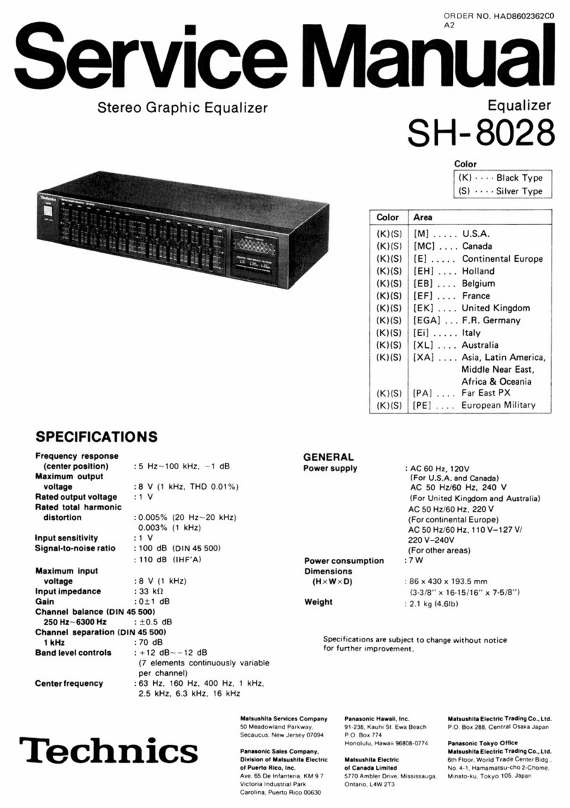
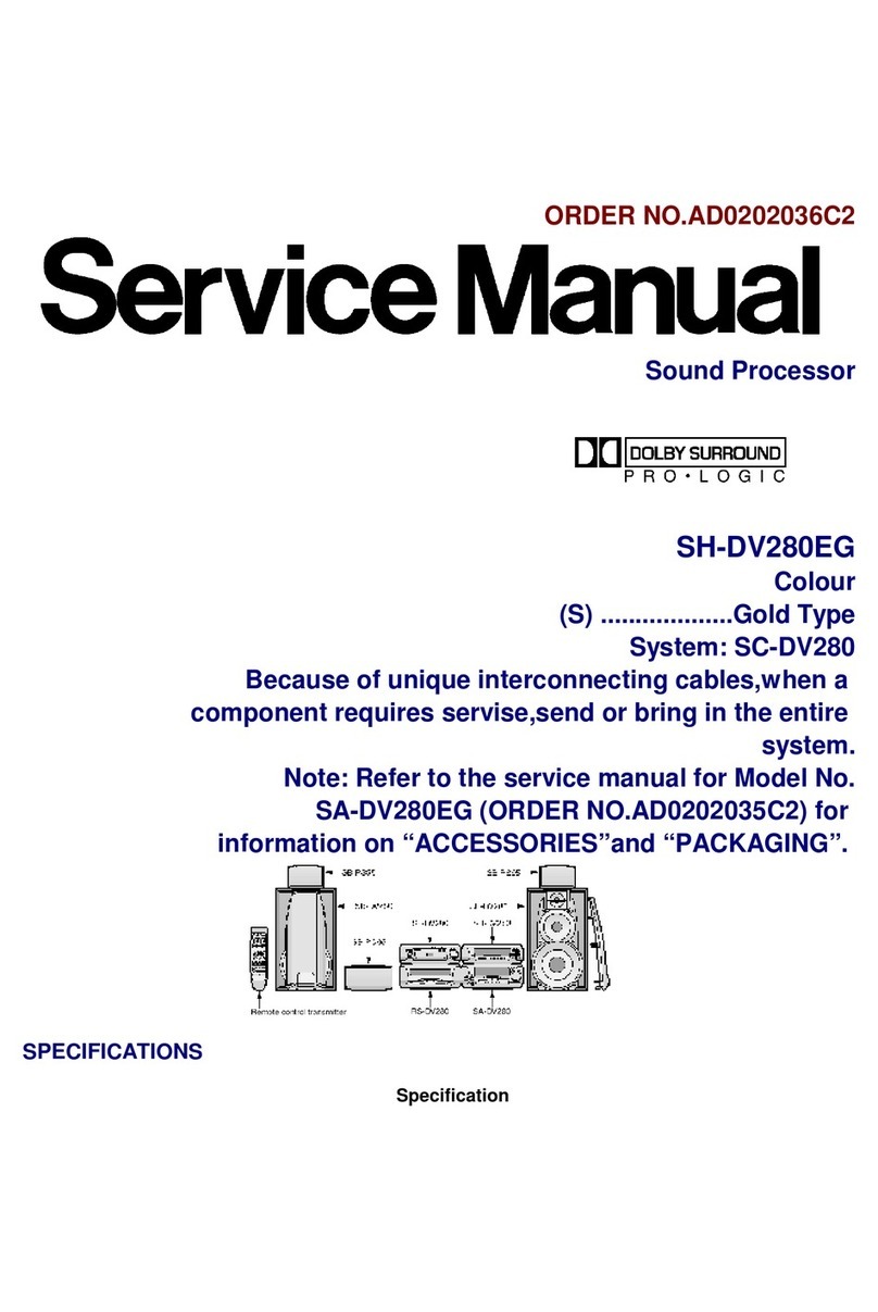
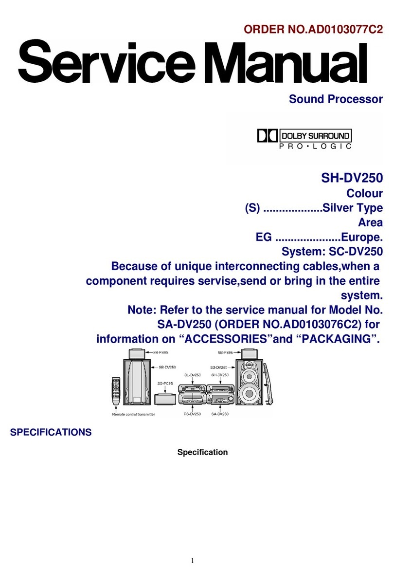
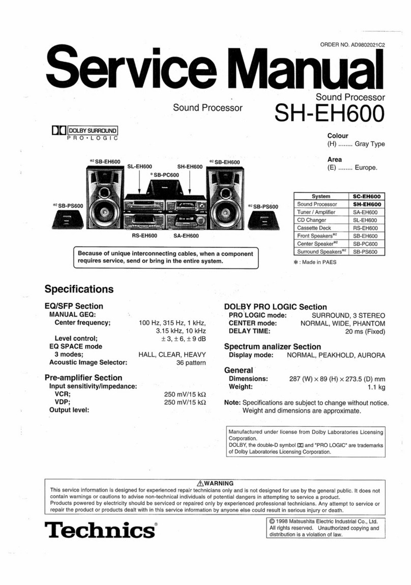
  7. Recording Equipment
  8. •
  9. Technics SH-EH50 User manual

Technics SH-EH50 User manual

ORDER
NO.
AD9703031C8
ervice
Manual
syacnpeeEnes
Sound
Processor
S
=
_
=
=
5O
For
(E)
/
(EP)
areas
*!
SB-EH60
*!
SB-EH60
Colour
Ta
ral
P
som
(K)
......
Black
SL-EH50
SH-EH50
Area
(E)/(EP)
...
Europe,
Russia.
(GC)
........
Asia,
Latin
America,
Remote
Control
Middle
East
and
A
Transmitter
Africa.
For
(GC)
area
*
SB-EH50
si-EH50
SH-EH50
~
SB-EH50
es
ssi?
SS
[For
(GC)
area
only]
i
wp
2
SB-PC60
D0
[potsy
surrounp
PRO-LOGIC
*2SB-PS60
nn
il
Remote
Control
Transmitter
Because
of
unique
interconnecting
cables,
when
a
component
requires
service,
send
or
bring
in
the
entire
system.
Specifications
EQ/SFP
Section
Spectrum
analizer
Section
MANUAL
GEQ:
Display
mode
:
NORMAL,
PEAKHOLD,
AURORA
Center
frequency
;
100
Hz,
315
Hz,
1
kHz,
3.15
kHz,
10
kHz
General
nevel
conttel
+3,6,9dB
Dimensions
:
287
(W)/89
(H)/273.5
(D)
mm
EQ
SPACE
mode
(3
modes)
:
HALL,
CLEAR,
HEAVY
Weight
:
1.1
kg
Acoustic
Image
Selector
:
36
pattern
DOLBY
PRO
LOGIC
Section
[For
(GC)
area
only]
Note:
Specifications
are
subject
to
change
without
notice.
PRO
LOGIC
mode
:
SURROUND,
3
STEREO
Weight
and
dimensions
are
approximate.
CENTER
mode:
NORMAL,
WIDE,
PHANTOM
DELAY
TIME
:
20
ms
(Fixed)
System/SC-EH50:
For
(E)/(EP)
area
Sound
processor:
SH-EH50,
Tuner/Amplifier:
SA-EH50,
Compact
disc
player:
SL-EH50,
Cassette
deck:
RS-EH60,
Front
speakers:
*!
SB-EH60
For
(GC)
area
Sound
processor:
SH-EH50,
Tuner/Amplifier:
SA-EH50,
Compact
disc
player:
SL-EH50,
Cassette
deck:
RS-EH60,
Front
speakers:
**
SB-EH50,
Center
speaker:
**
SB-PC60,
Surround
speakers:
**
SB-PS60
Notes:
>k1
...Made
in
PAES
2
...Made
in
MESA
ZA\AWARNING
This
service
information
is
designed
for
experienced
repair
technicians
only
and
is
not
designed
for
use
by
the
general
public.
It
does
not
contain
warnings
or
cautions
to
advise
non-technical
individuals
of
potential
dangers
in
attempting
to
service
a
product.
Products
powered
by
electricity
should
be
serviced
or
repaired
only
by
experienced
professional
technicians.
Any
attempt
to
service
or
repair
the
product
or
products
dealt
with
in
this
service
information
by
anyone
else
could
result
in
serious
injury
or
death.
T
J
e
6
©
1997
Matsushita
Electric
Industrial
Co.,
Ltd.
All
rights
reserved.
Unauthorized
copying
and
distribution
is
a
violation
of
law.
SH-EH50
@
Contents
Page
Page
LOCatOMiO
COMMONS
«cz:
ice;
cesses
escesce
ssessivencdsssztestseesecesseatssxceinahinertciseesvon
2
Printed
Circuit
Board
Diagram
ccsesiscesasecsncasesecaseveasevschessensecasavivesveeest
14
Changing
the
tONG
sissssisccssseesdtescssesiutlecsdccatendoussavesstastevtenveadaxdewestcaxees
3,4
Type
Illustration
of
IC's,
Transistors
and
Capacitors
...........sccscssesesee
15
Enjoying
sound
with
DOLBY
PRO
LOGIC
[For
(GC)
area
only].....
5,
6
Wiring
Connection
Diagram
Enjoying
with
SURROUND
or
3
STEREO
[For
(GC)
area
only]
.........
il
Terminal
Function
of
IC's
Operation
Checks
and
BloCK
DiaQrainy
siceccssscascsssnverseceveevcavieveevtevencensaceaves
Main
Component
Replacement
Procedures
.............:es0
8,9
Replacement
Parts
List
(Electrical
and
Cabinet)
....
Te:
Supply
POWGr
SOUICE
is
issicsscss:.ciissctacdsssy-csasesgeonesecesessnonesnenncsueiecoes
10
RESIStOFS
ANG
CAaPACIONS
\.
cscs
cesessccsecveeveseacsavesvescsnsorssesssesstsssenvessssevess
SCHEMARNG:
DIAG
AIM
ish
seisecs
sdees
evesedeevsawvcensaseseageacansevieevssvenvesueveceses
11
~13
Cabinet
Parts:
LOCAtiOn
siscs:..sasassssccvsasesacsetsneciosstaystracctia
rnin
aaeeniaeaees
NOTE:
Refer
to
the
service
manual
for
Model
No.
SA-EH50
(ORDER
No.
AD9703053C8)
for
information
on
“Accessories”,
“Connections”,
“Installation”
and
“Packaging”.
#
Location
of
Controls
@
EQ
SPACE
on/flat
button
(EQ
SPACE
ON/FLAT)
@
Display
mode
select/demonstration
button
(DISP
MODE/-DEMO)
@)
Display
@
DOLBY
PRO
LOGIC
indicators
(SURROUND,
3
STEREO,
NORMAL,
WIDE,
PHANTOM)
©)
Multi
control
buttons
(MULTI
CONTROL,
P
,
A,
<4,
W)
©
Acoustic
image
EQ
button
(ACOUSTIC
IMAGE
EQ)
@
EQ
SPACE
preset/manual
select
button
(PRESET/MANUAL)
DOLBY
PRO
LOGIC
on/off
button
(DOLBY
PRO
LOGIC,
OFF/ON)
@DOLBY
PRO
LOGIC
mode
select
button
(MODE)
[ele
eicekou
a
@DOLBY
PRO
LOGIC
test
signal
button
(TEST)
[le
kicckua
@DOLBY
PRO
LOGIC
center
mode
button
(CENTER
MODE)
[io
eicekoula
|
SH-EH50
m@
Changing
the
Tone
To
listen
with
augmented
bass
WALT.)
Press
V.
BASS.
To
cancel,
press
V.
BASS
once
again.
You
cannot
record
with
the
V.
BASS
effect.
“V.
BASS”
is
only
effective
on
sounds
which
can
be
heard
through
the
speakers
or
headphones.
Using
the
internal
sound
quality
B
Press
PRESET/MANUAL
to
select
the
desired
mode.
Each
time
you
press
PRESET
/MANUAL,
EQ
and
SPACE
modes
will
be
switched
as
follows.
HEAVY—
CLEAR
HALL
MANUAL
ee
ae
ee
|
GJHEAVY:
Use
toadd
“punch”
to
rock
and
other
music.
[2)CLEAR:
Use
to
clarify
the
treble
range
of
jazz,
etc.
[3]
HALL:
Use
to
impart
a
deep
bass
and
spread
which
will
make
you
feel
as
if
you
were
in
a
large
concert
hall.
[4]MANUAL:
Refer
to
the
“Finer
sound
quality
changes”
section
on
Page
4.
To
cancel
the
EQ
SPACE
effect
Press
EQ
SPACE
ON/FLAT
to
select
“FLAT”.
Recordings
cannot
be
made
in
the
HALL,
CLEAR,
HEAVY
or
MANUAL
modes.
Recording
during
use
of
sound
quality
operation
will
cause
the
“HALL”,
“CLEAR”,
“HEAVY”
and
“MANUAL”
indicators
to
dis-
appear
and
light
again
when
recording
is
completed.
PRESET/
SH-EH50
Middle
register
Ltt
WER
SS
SARE
ee
SL
ee
FETE
t
f
¥
Using
the
acoustic
image
EQ
This
function
allows
easy
creation
of
sounds
closer
to
what
you
imagine.
The
figure
shows
an
example
where
the
sound
quality
has
been
adjusted
to
HEAVY
level
2
and
SHARP
level
3.
il
Press
ACOUSTIC
IMAGE
EQ.
2
Press
the
A
VW
<
>
buttons
to
move
the
cursor
to
the
desired
music
image.
HEAVY
(A):
When
a
heavier
sound
is
desired
LIGHT
(¥):
Whena
lighter
sound
is
desired
SOFT
(<4):
|
Whena
softer
sound
is
desired
SHARP
(>):
Whena
sharper
sound
is
desired
To
cancel
the
ACOUSTIC
IMAGE
EQ
effect
Press
EQ
SPACE
ON/FLAT
to
select
“FLAT”.
Sounds
can
be
made
to
fit
a
total
of
36
images.
©The
resulting
adjustment
is
automatically
stored
in
memory.
When
the
ACOUSTIC
IMAGE
EQ
is
pressed
again,
the
image
last
selected
is
automatically
selected.
Finer
sound
quality
changes
Finer
sounds
can
be
created
by
selecting
MANUAL.
il
Press
PRESET/MANUAL
to
select
MANUAL.
Press
<
>
to
select
the
desired
register.
<4:
Upper
register
>:
Lower
register
EF}
Press
A
V
to
adjust
the
register
level.
A:
Increasing
the
register
level
V:
Decreasing
the
register
level
For
your
reference:
Upper
register:
includes
pipes,
strings,
cymbals
and
triangles
@
Increasing
the
upper
register:
mellows
pipes
and
strings,
adds
pre-
cision
and
glitter
©
Decreasing
the
upper
register:
quiets
music,
rids
music
of
its
“stretch”
Middle
register:
vocals
(voice)
@
Increasing
the
middle
register:
gives
strength
and
punch
to
music
brings
voices
forward,
brightens
sound
©
Decreasing
the
middle
register:
quiets
music,
pulls
voices
back,
softens
intense
sounds
Lower
register:
includes
bass
and
drums
©
Increasing
the
lower
register:
stabilizes
heavy
and
low
sounds,
swells
low
sounds
©
Decreasing
the
lower
register:
decreases
noise
in
lower
sounds,
re-
duces
muffled
sounds
©The
resulting
adjustment
is
automatically
stored
in
memory.
When
the
MANUAL
mode
is
selected
again,
the
sound
quality
last
se-
lected
is
automatically
played
back.
©The
register
can
be
manually
adjusted
at
5
individual
points
along
the
100
Hz~10
kHz
frequency
range.
|
SH-EH50
a
Enjoying
Sound
with
eee
PRO
LOGIC
[For
(GC)
area
only]
By
combining
front,
center
and
surround
speakers,
you
can
enjoy
the
SURROUND
mode
which
conveys
a
feeling
of
presence
or
the
3
STEREO
mode
which
conveys
a
feeling
of
orientation.
Front
Front
speaker
(L)
Center
speaker
speaker
(R)
;
|
SURROUND
y
By
reproducing
the
feeling
of
depth
and
movement
of
sound,
video
software
or
compact
discs
recorded
with
Dolby
Surround
provide
the
listener
with
the
sensations
of
a
movie
theater.
To
enjoy
SURROUND,
be
sure
to
connect
the
surround
speakers.
Surround
Surround
!
B
You
can
enjoy
audio/video
sources
with
clear
sound,
more
presence
and
enhanced
orientation.
3
STEREO
can
be
used
with
sources
not
recorded
in
DOLBY
SURROUND.
To
enjoy
3
STEREO,
be
sure
to
connect
the
center
speaker.
Front
Front
speaker
(L)
Center
speaker speaker
(R)
Manufactured
under
license
from
Dolby
Laboratories
Licen-
sing
Corporation.
DOLBY,
the
double-D
symbol
DO
and
“PRO
LOGIC”
are
trademarks
of
Dolby
Laboratories
Licensing
Corporation.
Setting
the
center
mode
For
Dolby
Pro
Logic
systems,
center
mode
setting
is
necessary
to
play
Surround
Surround
he
back
bass
sounds
effectively.
Set
the
center
mode
in
accordance
with
speaker
(L)
speaker
(R)
|
the
size
of
your
center
speaker.
il
Switch
on
the
power.
2
Press
DOLBY
PRO
LOGIC
OFF/ON
io
select
ON.
Jk]
Press
MODE
to
select
“SURROUND”
or
“3
STEREO”.
Each
time
you
press
the
button,
the
display
will
change
as
follows:
SURROUND-3
STEREO
tS
4
Press
CENTER
MODE
to
select
“NORMAL”
mode.
Each
time
you
press
the
button,
the
display
will
change
as
follows:
NORMAL
WIDE->PHANTOM
SRE
ae
ee
“PHANTOM”
will
not
be
displayed
when
you
select
“3
STEREO”
in
step
Eq.
NORMAL:
When
the
center
speaker
is
smaller
than
the
front
speakers
WIDE:
When
the
center
speaker
is
the
same
size
or
larger
than
the
front
speakers
PHANTOM:
When
no
center
speaker
is
connected
STANDBY,
In
the
PHANTOM
mode,
the
sound which
would
have
been
sent
to
the
center
speaker
will
be
divided
equally
between
both
the
left
and
right
front
speakers.
SH-EH50
|
OFF/ON
®
-
CENTER
+
Adjusting
speaker
output
level
In
order
to
reproduce
the
movement
of
the
sound
and
its
clear
orientation,
it
is
important
to
adjust
the
output
level
of
each
speaker.
Adjust
output
to
the
correct
levels
while
listening
to
the
test
signal.
il
Press
DOLBY
PRO
LOGIC
OFF/ON
to
select
ON.
Press
MODE
ito
select
“SURROUND”
or
“3
STEREO”.
Each
time
you
press
the
button,
the
display
will
change
as
follows:
SURROUND->3
STEREO
|
El
Press
TEST
to
output
a
test
signal.
The
test
signal
is
emitted
in
the
following
order:
For
SURROUND
mode
Front
speaker
(lefts
Center
speaker
Y
Surround
speakers
(left,
right)
Front
speaker
(right)
The
test
signal
is
not
emitted
from
the
center
speaker
when
the
center
mode
is
on
PHANTOM.
For
3
STEREO
mode
Front
speaker
(left)
Center
speaker—
Front
speaker
(right)
te}
Turn
VOLUME
to
set
the
volume
level
normally
used
for
enjoying
the
source.
5
Press
CENTER
(—)
or
(+)
or
SURROUND
(-—)
or
(+)
on
the
remote
control
to
adjust
the
output
level
balance.
Adjust
the
output
level
of
each
speaker
from
the
listening
posi-
tion
until
they
are
all
identical.
Output
levels
can
be
varied
within
a
range
of
+12
dB
with
front
speaker
output
level
serving
as
the
zero
point.
©The
test
signal
is
output
only
by
the
speaker
you
are
now
adjusting
and
does
not
repeat
the
sequence
until
adjustments
are
complete.
@Remember
you
cannot
adjust
the
output
level
of
the
surround
speakers
if
you
selected
the
3
STEREO
mode
in
step
SI
To
stop
the
test
signal:
Press
TEST.
SH-EH50
m@
Enjoying
with
SURROUND
or
3
STEREO
[For
(GC)
area
only]
.
Enjoying
with
SURROUND
or
3
STEREO
Before
trying
anything,
have
you
set
the
center
mode
and
adjusted
speaker
output
level?
When
viewing
a
video,
turn
on
the
power
supply
for
the
TV
and
set
the
TV
to
video
mode.
il
Press
INPUT
SELECTOR
to
select
the
desired
external
source.
Each
time
you
press
this
button,
sound
sources
will
be
switched
as
follows.
TUNER
—>
CD
—
TAPE
t
1
VDP(AUX)
<<
VCR(EXT)
These
indications
correspond
to
terminals
on
the
rear
panel
of
the
sound
processor
or
tuner/amplifier.
Switch
the
displayed
indication
to
the
source
you
want
to
use.
Press
DOLBY
PRO
LOGIC
OFF/ON
to
select
ON.
IN)
Press
MODE
to
select
“SURROUND”
or
“3
STEREO”.
eS
Start
the
desired
source.
To
operate
external
sources,
refer
to
the
operating
instructions
provided
with
the
specific
unit.
S
When
using
SURROUND,
use
software
recorded
in
Dolby
Surround.
To
turn
off
the
DOLBY
PRO
LOGIC
systems:
Press
DOLBY
PRO
LOGIC
OFF/ON
to
select
“OFF”.
You
cannot
record
acoustical
effects
produced
in
the
SURROUND
and
3
STEREO
modes.
SH-EH50
|
@
Operation
Checks
and
Main
Component
Replacement
Procedures
\\(oyg=8
1.
This
section
describes
procedures
for
checking
the
operation
of
the
major
printed
circuit
boards
and
replacing
the
main
components.
2.
For
reassembly
after
operation
checks
or
replacement,
reverse
the
respective
procedures.
Special
reassembly procedures
are
described
only
when
required.
1.
Checking
for
the
IN/OUT
terminal
P.C.B.
Remove
the
top
cabinet.
¢
Check
the
IN/OUT
terminal
P.C.B.
as
shown
below.
Connect
the
lead
wire.
Top
cabinet
IN/OUT
terminal
P.C.B.
Step
6
Release
the
3
claws,
and
then
remove
the
IN/OUT
terminal
P.C.B..
|
SH-EH50
_
2.
Checking
for
the
FL
P.C.B.
¢
Follow
the
~
of
the
item
1
in
checking
procedure
for
each
P.C.B.
on
page
8.
Release
the
6
claws,
and
then
remove
the
front
panel
ass’y.
Release
the
5
claws,
and
then
¢
Check
the
FL
P.C.B.
as
shown
below.
remove
the
FL
P.C.B..
Unsolder
the
shield
plate
terminals.
(6
points)
SH-EH50
|
m@
To
Supply
Power
Source
This
unit
SH-EH50
is
designed
to
operate
on
power
supplied
from
the
Tuner/Amplifier
SA-EH50.
When
operating
the
unit
SH-EH50
alone
for
testing
and
servicing,
without
having
power
supplied
from
the
Tuner/Amplifier
SA-EH50,
use
the
following
method.
Power
Supply
to
Video
Selector
Circuit
1.
Short
the
section
between
J124
and
R753:
2.
Short
the
section
J306,
J307,
J305
and
J302
with
each
other.
(Point
EY)
3.
Short
the
section
between
J126
and
17
pin
of
the
connector
JK101.
(Point
[)
4.
Short
the
section
between
J125
and
J101.
(Point
[@)
5.
Apply
+5
V
DC
power
to
the
section
between
J125
and
(+)
foil
side
of
C104.
6.
Connect
the
DC
power
supply
as
shown
below.
©
+12
V
terminal
of
the
DC
Power
Supply
connect
to
Point
fq.
©
GND
terminal
of
the
DC
Power
Supply
connect
to
Point
EN.
®@—12
V
terminal
of
the
DC
Power
Supply
connect
to
Point
EJ.
To
Check
Signal
1.
Input
the
audio
signal
and
confirm
in
to
be
outputted
from
the
terminal.
az
INPUT
OUTPUT
VCR-Lch
terminal
.
_VCR-Rch
terminal
DC
Power
Supply
Short
Point
E}
Short
EN
Short
Point
EY
Short
Point
Short
EJ
JK101-17
pin
DC
Power
Supply
——J302
“>
J307
seine
|
=
J305
C104+
J125
Short
ka
D101
J125
J124
+5V
a
|
Short
=40=
SH-EH50
mSchematic
Diagram
Page
PY
FL
CIRCUIT
cimimoiiaimacincenaqeinntoeneinnnad
i
FE]
IN/OUT
TERMINAL
CIRCUIT
.......+:scssscsessssseesserseecstssstsententssensesteennees
13
®
This
schematic
diagram
may
be
modified
at
any
time
with
the
development
of
new
technology.
Notes:
@
$301:
EQ
SPACE
on/off
switch
(EQ
SPACE
ON/FLAT)
®@
$302:
Acoustic
image
EQ
switch
(ACOUSTIC
IMAGE
EQ)
®@
$303:
EQ
SPACE
preset/manual
select
switch
(PRESET/MANUAL)
®
$304:
Display
mode
select/demonstration
switch
(DISP
MODE/-DEMO)
®@
$305:
DOLBY
PRO
LOGIC
on/off
switch
(DOLBY
PRO
LOGIC,
OFF/ON)
[For
(GC)
area
only]
®
$306:
DOLBY
PRO
LOGIC
mode
select
switch
(MODE)
[For
(GC)
area
only]
®@
$307:
DOLBY
PRO
LOGIC
test
signal
switch
(TEST)
[For
(GC)
area
only]
e@
$308:
DOLBY
PRO
LOGIC
center
mode
select
switch
(CENTER
MODE)
[For
(GC)
area
only]
®@
$310
~
$313
:
Multi
control
switch
(MULTI
CONTROL
,
$310:
W,
$311:
<@,
S312:
A,
S313:
)
@
Indicated
voltage
values
are
the
standard
values
for
the
unit
measured
by
the
DC
electronic
circuit
tester
(high-impedance)
with
the
chassis
taken
as
standard.
Therefore,
there
may
exist
some
errors
in
the
voltage
values,
depending
on
the
internal
impedance
of
the
DC
circuit
tester.
®
Voltage
values
and
waveforms
are
measured
as
indicated
in
the
schematic
diagram
when
test
points
between
and
(eg,
and
between
and
[eel
,
and
between
[EXe¥
and
[ife¥
are
shorted.
®
Important
safety
notice:
Components
identified
by
/\
mark
have
special
characteristics
important
for
safety.
Furthermore,
special
parts
which
have
purposes
of
fire-retardant
(resistors),
high-quality
sound
(capacitors),
low-noise
(resistors),
etc.
are
used.
When
replacing
any
of
components,
be
sure
to
use
only
manufacturer’s
specified
parts
shown
in
the
parts
list.
®
Caution!
IC
and
LSI
are
sensitive
to
Static
electricity.
Secondary
trouble
can
be
prevented
by
taking
care
during
repair.
Cover
the
parts
boxes
made
of
plastics
with
aluminum
foil.
Ground
the
soldering
iron.
Put
a
conductive
mat
on
the
work
table.
Do
not
touch
the
legs
of
IC
or
LSI
with
the
fingers
directly.
®
Voltage
and
signal
line
mmmpesss
:
Positive
voltage
line
anamj==mem
:
Negative
voltage
line
mam>
:
Spectrum
analyzer
signal
line
S44
SH-EH50
|
Al
FL
CIRCUIT
(P.C.Board:on
page
14)
FL401(RSLO235-
F)
FL
DISPLAY
SOOCCOCSCEC
OE
CCS
COB
COO
CCG
DDO
COO
OS
IVOOOIe®
TTT
TT
TT
wa
—
les
I
bic
ABCDEFGHIJSKL
MNOPQRSTU
t
if
L=
For
(E,EP)
areas.
ABCDEFGHIJKL
1401
LC65366A4H96
SYSTEM
CONTROL
[FL
DRIVE
Terminal
gu
on
page
16
cHoowymov)d879
ze
For
(GC)
area.
C416
|,
47P
C413
,,
47P
402,403
ie
2$C3311AIQST
rae
FL
DRIVE
Q401
UN4211AITA
X401
F=4MHz
(4MHz)
$301
(EQ
SPACE
ON/FLAT)
o
Oo
$302(ACOUS.
IMAGE
EQ)
R317
820
1K
$303(PRESET/
MANUAL)
R319
«R318
1.2K
R320
1.5K
1C301
BU2090F-
E2
:
2SD2144STA
LED
DRIVE
b
POWER
SUPPLY
R321
1.8K
R322
2.2K
D301
(SURROUND)
~~
“SAA
R325
R324 R323
6.8K
4.7K
3.3K
es
ot
eee
R326
12K
UN4211AITA
MUTING
R327
22K
R328
68K
D301-
305
Lauer
CONTROL)
LNJ301MPUJAD
Dolby
PRO
LOGIC)
=
_
7
= =
|
For
(GC)
area.
SH-EHS0
smaa=p===<=
-:
Positive
voltage
line
seee==e=2
~-
Negative
voltage
line
ee
:
Spectrum
analyzer
signal
line
FE}
IN/OUT
TERMINAL
CIRCUIT
(P.c.Board:on
page
14)
E101
@)
(VIDEO.GND)
(A.GND)
VG
a
=
Eo
SPE.ANALYZER
SIGNAL
ABCDEFGH
|°*
9
C156
16V10
XXSX0me
OO)
)
CD
se/
SUPER
AME
GY)
GYAX3V2)
BUFFER
AMP
1)
e
é
+
te
oo
A
&
@='
Qi03
b
“”
28D2137PQTA
REGULATOR
14.1V
5.9V
an
5.5V
BE\+
Aptos
oS
4062HTA
10801
°
C104
.
35V470
BA3835F-E1
SPE.ANALYZER
AMP
AIDB|$
al
oO
Q101
-24y102
44,
we
2
Sy
aie
C2
-0.1V
Q101,102
Cart.
)
2SD1450STA
Cele
FL
DRIVE
104
UN4111AITA
[
eG
FL
DRIVE
FLU)
FL
Ny
sYN¢
(8
To
SA-EH50:W202
on
page
32
ae
ce
SH-EH50
|
@
Printed
Circuit
Board
Diagram
®
This
circuit
board
diagram
may
be
modified
at
any
time
with
the
development
of
new
technology.
A
FL
P.C.B.
|B
|
IN/OUT
TERMINAL
P.C.B.
(A.GND)
.,
1
\\__.{
ACOUSTIC
IMAGE
EQ
405
fyi
*a
(
REP2474D-M...[GC]
(
REP2474D-M...[GC]
REP2474E-M...[E,EP]
REP2474E-M...[E,EP]
tA
SH-EH50
@
Type
Illustration
of
IC's,
Transistors
and
Diodes
BU2090F-E2
|16PIN
BA4558FDXE2
LC65366A4H96
2SD2137PQTA
25C3311AlQST
BA3835F-E1
|18PIN
2SD1450STA
UN4111AITA
Sy,
UN4211AITA
8
is
BZ
.
AF
E
4
E
_|
o
3
28D2144STA
MA4051MTA
18S291TA
LNJ301MPUJAD
MA4062HTA
MA165TA
Ca
a
Cathode
eT
oe
ee
5)
A
a
A
@
Wiring
Connection
Diagram
BI
IN/OUT
TERMINAL
P.C.B.
FW401A
FW402A
CUT
=
TTT
FW401B
402B
i
SH-EH50
@
Terminal
Function
of
IC's
©
1C401
(LC65366A4H96)
CU
Name
a
ee
Pa
[resrao
[1
[est
eseeysomive
Pe
[oar
[friar
Fe
[ae
|=
fromrnavremin
cas)
[ee
fe
ensintame
es
a
pe
|
osct
|
i
Oscillator
connected
terminal
(4
MHz)
OSC2
[2
[
v0
|=
[oer
/RES
S|
Reset
signal
input
12,13)
7G,
6G
|
0
|
Grid
signal
output
Communication
data
signal
input
from
15
Sl
VO
|
sa-cH60
—
hows
Select
terminal
for
Spectrum
analyzer
IC
output
Serial
communication
signal
from
SA-EH60
(Clock
signal
input)
(Chip
enable
signal
input)
Grid
signal
output
Serial
communication
signal
from
SA-EH60
oOo
|
o@
oo
on
|
3
4~-45|
P12~P1
46,47!
10G,
9G
NC
Negative
power
supply
Serial
data
signal
output
Serial
clock
signal
output
Select
terminal
for
Spectrum
analyzer
IC
fw
|
ove
[o
[mm
SPEANA
P|
Analog
signal
input
for
spectrum
analyzer
IC
fez}
cs
|u|
Chip
select
signal
input
terminal
cial
x6
[—|Noumepen
=16=
@
Block
Diagram
For(GC)area.
|
|
|
LED
DR
=
@~1
©
8BR
O
DATA
Lch
IN
Reh
IN
A.GND
Leh
OUT
Reh
OUT
|
SH-EH50
NOTES:
1)
(
)INDICATES
Pin
No.OF
RIGHT
CHANNEL.
=———
=
=|
2)
=>
SPE.
ANALYZER
SIGNAL
E2
IVE
D402
Voo
bis!
4—Ga)i)
=
ee
|
D301-
305
ash
os
Sol
Te
PoweR
SUPPLY
y
2401
ee}
toe
|
[Eg
SIGNAL
GENERATOR
as
oof
—
Q10
Ive
2
BA4558FDXE2
1C101
BUFFER
AMP
r-—4
Vee(t)
REGULATOR
CT.GND
V.GND
D.GND
CT.GND
ace
EHSo
5
BAS@35F-E1
:
1501
at
Vee(2)
SPE,
ANALYZER
AMP
|,
4.8
r=—-————5
ee
AIN
[CIN
[DIF
OUT
KEY
18
|
ritbeno
[
oF
J
CE
|
|
cLK
|
10.5kHz|
|
3.4kHz
s4otiz
|
|
tosHz
|
|
BPF BPF BPF BPF
8
DATA
8
Voc
|
|
[
RES
|
PEAK
HOLD
|
“VR
psor
|
|,
Bi
(1)
GB)
re
DEC
MPX
|
wa
i
a a
ae
|
10
11
12
17
SYNC
107,
102,
104
8
Gd
ee
ie
ae
ee:
ae
z<*xsxwuwag
<
oa
=
<
7
Ea
oO
Oo
€ o o
z z
DRIVE
=
a
¢
LC65366A4H96
a G
S
a
|
=
a
a
1C401
G
G
SYSTEM
CONTROL/FL
DRIVE
3
I
=
N
KE
wd
|
6
2
9 9
8
2
ag
gee
ees
Bs
3
6g
#
e_|
Oo
One
=>
Oa
Sm
Ome
ee
Oo
ee ee
ee
es
es
eG
1]13]12)5]47
[s5]46
igc
8
9
fit
2
2
For
(GCJarea.
FL
s
|
$305-
308
I
DRIVE
Ev.
I
=
~~]
ao
oe
a™~o
|
402,403
GB)
—
=
—]
0404
a
|
PF
-4
|
|
ss01-304,310-313
SWITCHING
FL
DISPLAY
|
sa
oe
FL401
t=
ee
|
401
a{7=
SH-EH50
lm
Replacement
Parts
List
(Electrical
and
Cabinet)
Notes:
“Important
safety
notice:
Components
identified
by
A
mark
have
special
characteristics
important
for
safety.
Furthermore,
special
parts
which
have
purposes
of
fire-retardant
(resistors),
high-quality
sound
(capacitors),
low-noise
(resistors),
etc.
are
used.
When
replacing
any
of
components,
be
sure
to
use
only
manufacture’s
specified
parts
shown
in
the
parts
list.
“The
parenthesized
indications
in
the
Remarks
columns
specify
the
areas.
(Refer
to
the
cover
page
for
area.)
Parts
without
these
indications
can
be
used
for
all
areas.
*[M]
Indicates
in
Remarks
columns
parts
that
are
supplied
by
MESA.
*The
“(SF)”
mark
denotes
the
standard
part.
Part
Name
&
Description
Part
Name
&
Description
EVQ21405R
SH
INTEGRATED
CIRCUIT
(S)
EVQ21405R
Ww
—|
_
BA4558FDXE2
LC65366A4H96
BU2090F-E2
EARTH
TERMINAL
(S)
BA3835F-E1
TRANSISTOR
(S)
SNE1004-2
EARTH
TERMINAL
JACK
(S)
2SD1450RTA
|
TRANSISTOR
28D2137PQTA
|
TRANSISTOR
UN4111
TRANSISTOR
2SD2144STA
|
TRANSISTOR
UN4211
TRANSISTOR
2SC3311AIRTA
|
TRANSISTOR
UN4111
TRANSISTOR
UN4211
TRANSISTOR
MA4062-H
DIODE
(M]
LNJ3O1MPUJAD
|L.
E.
D.
[M
(GC)
MAI65TA
DIODE
Giada
18S291TA
DIODE
(M
(GC)
MA165
DIODE
MA4OS1MTA
DIODE
18S291TA
DIODE
MA165
DIODE
Ref.
No.
Part
No.
Part
Name
&
Description
Remarks
1
2
RHD30007-K1
[SCREW
0
3
XTB3+8JFZ
[SCREW
0
RKMO302-K
|CABINET
3/3/5
FL
HOLDER
M)
RYKO700C-K
|BOTTOM
CABINET
ASS’
Y
(M]
(E,
EP)
RYKO700F-K
|BOTTOM
CABINET
ASS’
Y
5-1
5
s_
|
6-2
SHG1654
RUBBER
[M]
RYPO733B-K
|FRONT
PANEL
ASS’
Y
[M]
(E,
EP)
RYPO733C-K
|FRONT
PANEL
ASS’
Y
(M0
(GC)
[M]
RKWO504-V
=
|FL_
PANEL
RGLO358-Q
|
(Mf)
(GC)
RMZ0423
SHEET
(Mf)
(GC)
XTBS3+8JFZ1
|SCREW
COIL
(S)
——|
XTB3+8JFZ
SCREW
RWJ5710240KK
|FLAT
CABLE
(FW401/10P)
[M]
RLQALOOJT-Y
COIL
—
OSCILLATOR
(S)
RWJ5705240KK
|FLAT
CABLE
(FW402/5P)
|
(Mi)
EFOEC4004T4
[OSCILLATOR
DISPLAY
TUBE
DISPLAY
TUBE
SWITCH(ES)
ee
ie
SW
=e
|
SH-EH50
M™@
Resistors
and
Capacitors
|
Notes
:
*
Capacity
values
are
in
microfarads
(uF)
unless
specified
otherwise,
P=Pico-farads
(pF)
F=Farads
(F)
|
*
Resistance
values
are
in
ohms,
unless
specified
otherwise,
1K=1,000(OHM)
,
1M=1,
000k(OHM)
Values
&
Remarks
No.
Values
&
Remarks
aoe
|
|
RCE1VW471BV
ERQUGNKW2R2E
|
1/eW
22
TM
ECEALHKAR22B
ERDS2TJ104
|
1/4¥
100K
OW
ECBTIE103ZF
ERDS2TJ822
|
1/4¥
8.2K
OM
RCE1CKA100BG
_[zros2ts222
1/W
2.2K
DM
RCE1CKALOOBG
ERDS2TJ563
|
1/4¥
56K
[Mi]
ECBT1HIOIKBS
|
|ERDS2TJ333
_
[awk
RCE1CKA100BG
ERDS2TJ181T
|
1/4¥
180
OM
ECBTIE103ZF
ERDS2TJ820T
|
1/4W
82
(M0
(GC)
ECBT1HIO2KB5
D0
(E,
EP)
BRDS2TJ222T
|
1/4W
2.2K
(M)(GC)
RCE1CKA1O0BG
DM
(Gc)
1/4W
2.2K
[M0
(GC)
ECBTLHIO4ZF5
|
50V
na
(GC)
ERDS2TJ821
|
1/4¥
820
IM
ECBTIHA70J5
|
50V
Ml
(GC)
ERDS2TJ102
|
1/4¥
1K
[
ECBTIHA70J5
|
50V
MM
GC)
‘
ERDS2TJ122
1/4W¥
1.2K
RCEQJKA470BG
|
6.
3V
~—‘eRps2TJ152
|
1/4W
1.5K
ECEALHKA2R2B
|
50V
ERDS2TJ182
|
1/4W
1.8K
[
|[RCELHKASR3BG
|
50V
ERDS2TJ222
|
1/4W
2.2K
RCEOJU102BV
ERDS2TJ332
|
1/4W
3.3K
RCE1CKA100BG
ERDS2TJ472
|
1/4
4.7K
[
ECEALHKA330B
ERDS2TJ682T
|
1/4R
6.8K
[
RCE1HKA3R3BG
ERDS2TJ123
12K
ECEALHKA330B
ERDS2TJ223
|
1/4W
22K
[
ECBTIHIO4ZF5
|
SOV
0.
1U
ERDS2TJ683
|
1/4W
68K
[
ECBTIE1032F
|
25V
0.01U
ERDS2TJ472T
|
1/4¥
4.7K
[M)(GC)
ECEADJKS101B
|
6.3
1000
10K
(M0
(6c)
ECBTIWA70J5
|
SOV
47P
1/AW
100K
OM
ECBTIHA70J5
|
50V 47?
1/4W
5.6K
[M
(Go)
ECBTIHIO1KBS
|
50V
100P
1/4
10K
OM
ECBTIHIO1KBS
|
50V
100P
ERDS2TJ562T
|
1/4¥
5.6K
[MI
(Gc)
RCEICKAL00BG
|
16V
10U
ERDS2TJ102
|
1/4¥
1K
[M
ECEALHKAORIB
|
50V
0.
1U
ERDS2TJ102T
|
1/48
1K
[MJ
(Gc)
ECBTIE1032F
|
25V
0.01
ERDS2TJ102
|
1/4¥
1K
MM
ERDS2TJ102
|
1/4¥
1K
[Ml
___[eros2tvez2[1/4W
82K
DO
ERDS2TJ102
|
1/4¥
1K
DM
ERDS2TJ101
|
1/4¥
100
[M
~
/ERDS2TJ102
[aw
1K
00
ERDS2TJ103
|
1/4
10K
IM
~-‘Terps2ts472
|
1/4W
4.7K
DE
EP)
BRDS27J104
|
1/4¥
100K
[MI
ERDS2TJ102
|
1/4
1K
OW
ERDS2TJ103
|
1/4¥
10K
MM
[ERDS27J563
[1a
56K
1M
ERDS2TJ103
|
1/4
10K
OM
IERDS2TJ102
|
1/4
1K
IM
l=
—t
a0
RESISTORS
ECALEM101B
3/3/3/5/3|5/3/3|s
3|3/3/3/3/3/3/3/3/3/5(8|/8|8
3|3|5
CAPACITORS
=
ce
SH-EH50
@
Cabinet
Parts
Location
Printed
in
Japan
F970311200HS/KH
~20-

Other Technics Recording Equipment manuals

Technics SH-EH600 User manual

Technics

Technics SH-EH600 User manual

Technics SH-DV290EG User manual

Technics

Technics SH-DV290EG User manual

Technics SH-8029 User manual

Technics

Technics SH-8029 User manual

Technics SY-FD20 User manual

Technics

Technics SY-FD20 User manual

Technics SH-8017 User manual

Technics

Technics SH-8017 User manual

Technics SH-8029 User manual

Technics

Technics SH-8029 User manual

Technics SH-8028 User manual

Technics

Technics SH-8028 User manual

Technics SH-DV250 User manual

Technics

Technics SH-DV250 User manual

Technics SH-8055 User manual

Technics

Technics SH-8055 User manual

Technics SH-8029 User manual

Technics

Technics SH-8029 User manual

Technics SY-FD20 User manual

Technics

Technics SY-FD20 User manual

Technics SH-DV280EG User manual

Technics

Technics SH-DV280EG User manual

Technics SH-GE90 User manual

Technics

Technics SH-GE90 User manual

Technics SH-8065 User manual

Technics

Technics SH-8065 User manual

Technics SH-EH750 User manual

Technics

Technics SH-EH750 User manual

Technics SH-E5 User manual

Technics

Technics SH-E5 User manual

Popular Recording Equipment manuals by other brands

Harman BSS Soundweb London BLU-USB installation guide

Harman

Harman BSS Soundweb London BLU-USB installation guide

Tektronix MTX100 user manual

Tektronix

Tektronix MTX100 user manual

Meinberg DCF600HS Setup guide

Meinberg

Meinberg DCF600HS Setup guide

DOEPFER A-155 manual

DOEPFER

DOEPFER A-155 manual

Lexicon PCM 91 user guide

Lexicon

Lexicon PCM 91 user guide

Iconix HD-RH1F user manual

Iconix

Iconix HD-RH1F user manual

Cedar dns2000 manual

Cedar

Cedar dns2000 manual

Yamaha TX-7 Performance notes

Yamaha

Yamaha TX-7 Performance notes

Carrier DLS VRF Installation and operating instructions

Carrier

Carrier DLS VRF Installation and operating instructions

ARM IM-AD1 user guide

ARM

ARM IM-AD1 user guide

Philips CDR-775 Instructions for use

Philips

Philips CDR-775 Instructions for use

DAELECTRONICS ICTRL-R-MINI Operation manual

DAELECTRONICS

DAELECTRONICS ICTRL-R-MINI Operation manual

Behringer X-Touch Compact quick start guide

Behringer

Behringer X-Touch Compact quick start guide

Alesis VX 49 quick start guide

Alesis

Alesis VX 49 quick start guide

Tema Telecomunicazioni AA-11 Technical manual

Tema Telecomunicazioni

Tema Telecomunicazioni AA-11 Technical manual

Aeta Audio Systems SCOOP STUDIO user manual

Aeta Audio Systems

Aeta Audio Systems SCOOP STUDIO user manual

Dedicated Micros SD Advanced Installation and operation guide

Dedicated Micros

Dedicated Micros SD Advanced Installation and operation guide

Hitachi SM 6145 Installation operation & maintenance

Hitachi

Hitachi SM 6145 Installation operation & maintenance

manuals.online logo
manuals.online logoBrands
  • About & Mission
  • Contact us
  • Privacy Policy
  • Terms and Conditions

Copyright 2025 Manuals.Online. All Rights Reserved.