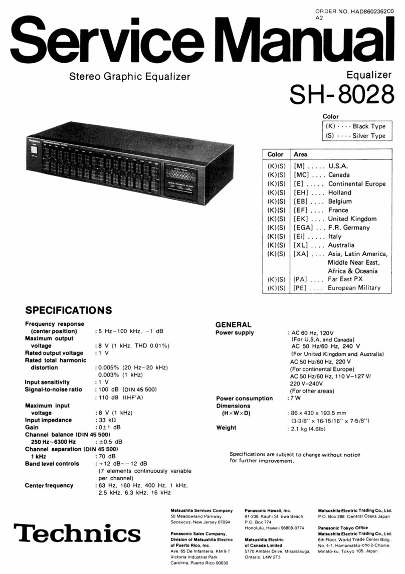
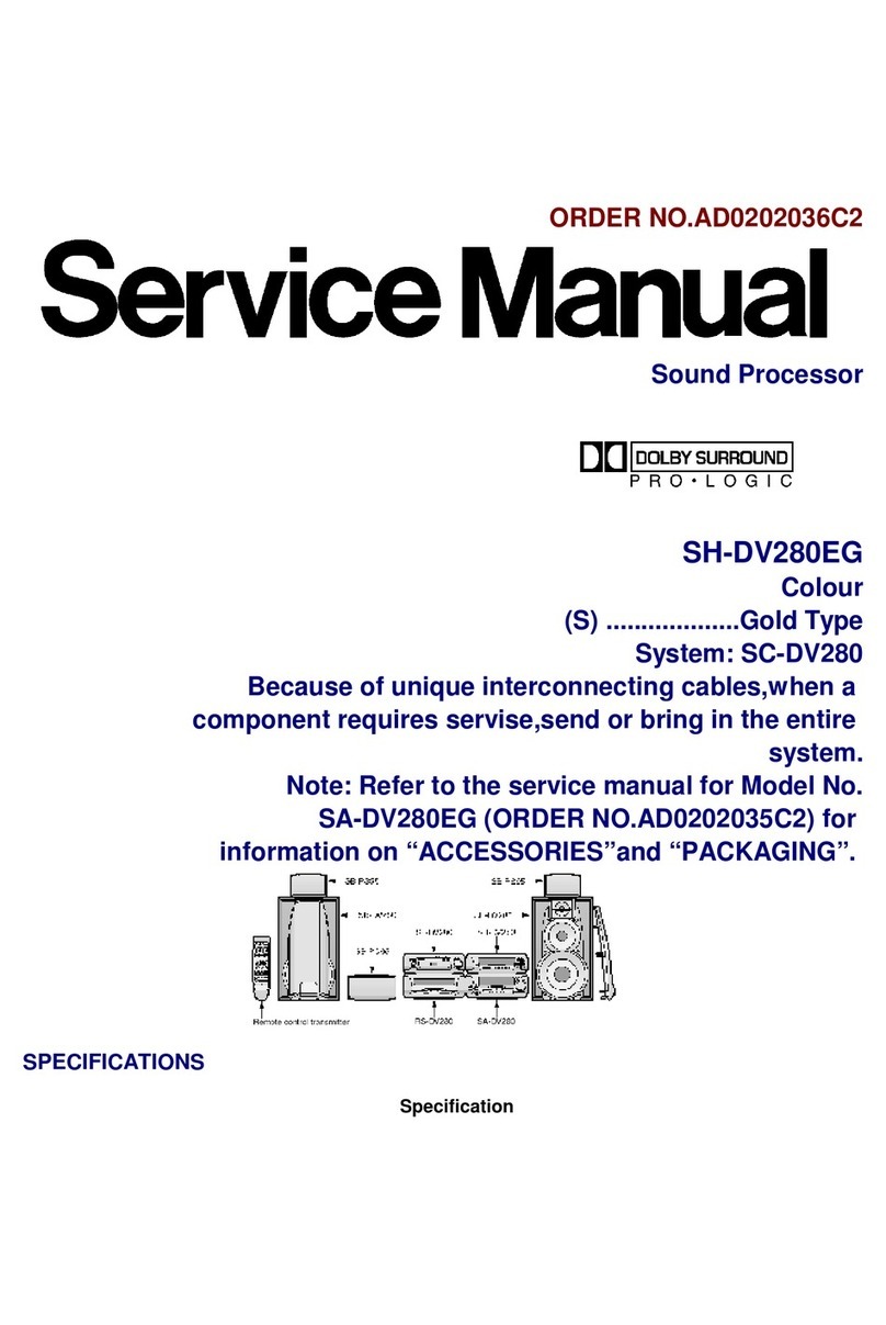
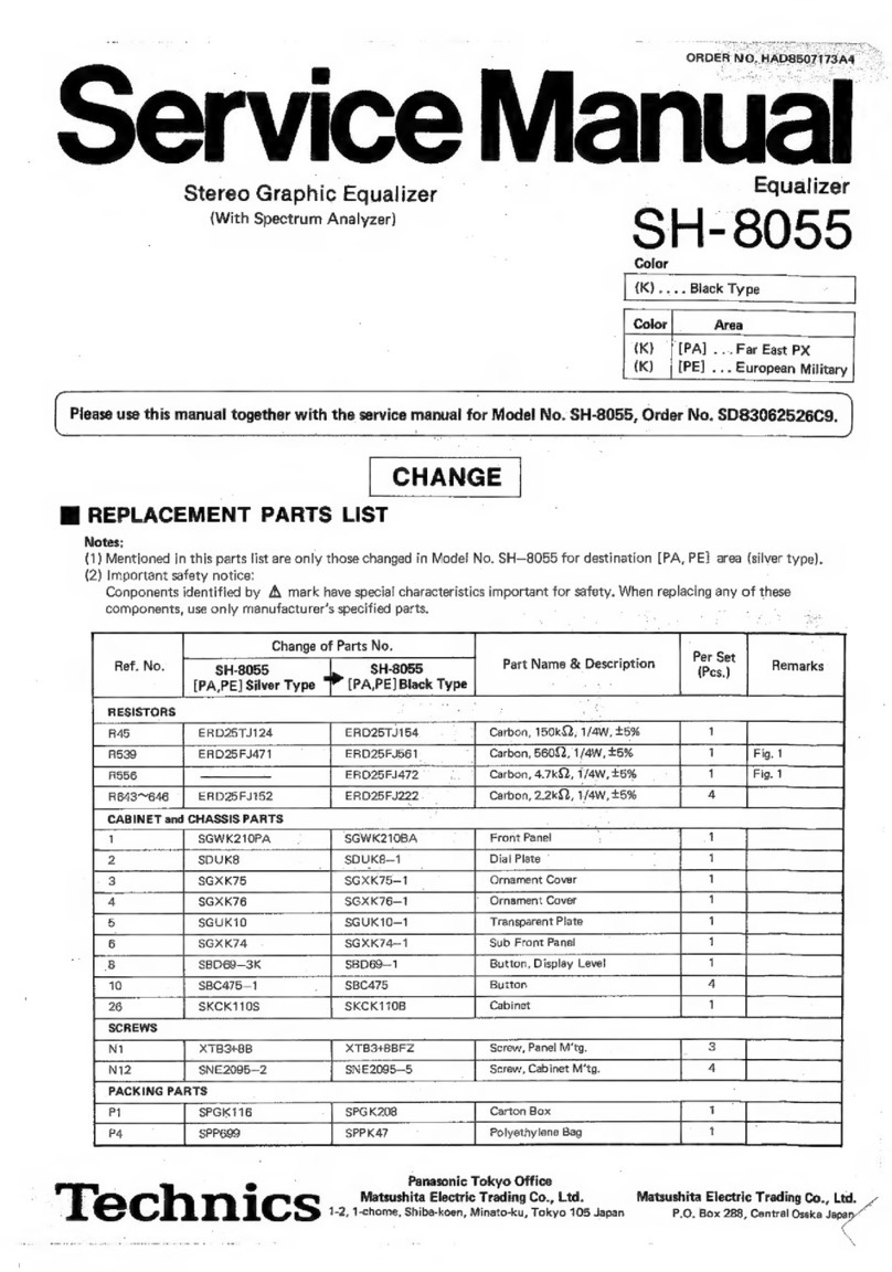
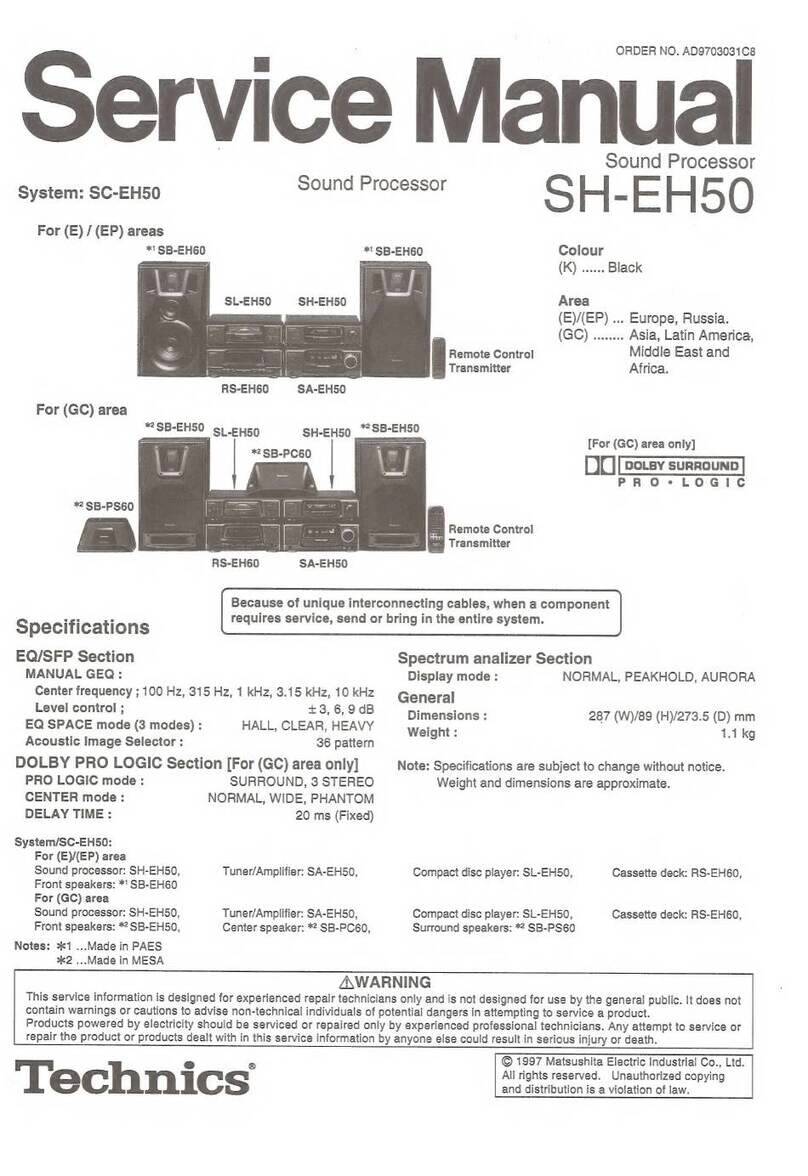
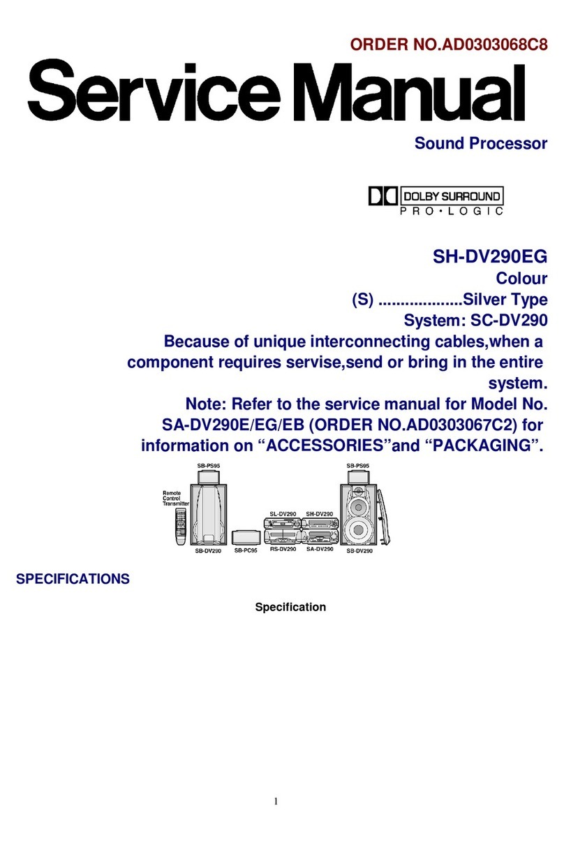
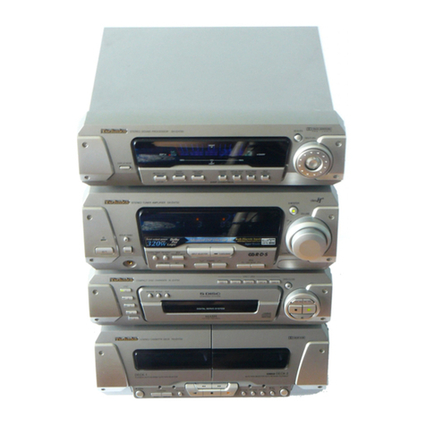
Technics SH-EH600 User manual

ORDER
NO.
AD9802021C2
Service
Manual
Sound
Processor
Sound
Processor
SH-EH600
DU
[satay
suman
Pome.
PRO-LOGICGC
|
|
Colour
|
(ED)
Gevlates
Gray
Type
“#2
SB-EH600
|
_
Area
*2
SB-EH600
ee
(=)
eee
Europe.
mw
SL-EH600
SH-EH600
*
SB-PC600
|
__
System
___|_
SC-EH600
|
*2
SB-PS600
Because
of
unique
interconnecting
cables,
when
a
component
requires
service,
send
or
bring
in
the
entire
system.
*
:
Made
in
PAES
Specifications
-
EQ/SFP
Section
|
DOLBY
PRO
LOGIC
Section
MANUAL
GEQ:
,
-.
PRO
LOGIC
mode:
©
SURROUND,
3
STEREO
Center
frequency;
100
Hz,
315
Hz,
1
kHz,
CENTER
mode:
NORMAL,
WIDE,
PHANTOM
3.15
kHz,
10
kHz
DELAY
TIME:
20
ms
(Fixed)
Level
control;
+3,+6,+9dB
EQ
SPACE
mode
Spectrum
analizer
Section
3
modes;
HALL,
CLEAR,
HEAVY
Display
mode:
NORMAL,
PEAKHOLD,
AURORA
Acoustic
Image
Selector:
36
pattern
|
|
|
General
Pre-amplifier
Section
Dimensions:
287
(W)
x
89
(H)
x
273.5
(D)
mm
Input
sensitivity/impedance:
-
Weight:
1.1
kg
VCR;
250
mV/15
kQ
|
|
:
VDP;
250
mV/15
kQ
Note:
Specifications
are
subject
to
change
without
notice.
_
Weight
and
dimensions
are
approximate.
Output
level:
|
Manufactured
under
license
from
Dolby
Laboratories
Licensing
Corporation.
-
DOLBY,
the
double-D
symbol
OO
and
"PRO
LOGIC"
are
trademarks
of
Dolby
Laboratories
Licensing
Corporation.
Z\WARNING
This
service
information
is
designed
for
experienced
repair
technicians
only
and
is
not
designed
for
use
by
the
general
public.
It
does
not
contain
warnings
or
cautions
to
advise
non-technical
individuals
of
potential
dangers
in
attempting
to
service
a
product.
Products
powered
by
electricity
should
be
serviced
or
repaired
only
by
experienced
professional
technicians.
Any
attempt
to
service
or
repair
the
product
or
products
dealt
with
in
this
service
information
by
anyone
else
could
result
in
serious
injury
or
death.
Technics
©
1998
Matsushita
Electric
Industrial
Co.,
Ltd.
All
rights
reserved.
Unauthorized
copying
and
distribution
is
a
violation
of
law.

SH-EH600
|
@
Contents
Page
Page
LOCALION/OT
COMMONS
sssinsessascoussaieanlesesievctsesiecanyScudiessiedeaeeccecoee
2
‘Type
illustration
of
IC's,
Transistors
and
Diodes
...................
10
Operation
Checks
and
Wiring
Connection
Diagram
..........cceccsccsscsscescssesccesetscnseeaes
10
Main
Component
Replacement
Procedures..........
3,4
Terminal
Function
of
IC's...
ccecsscscssccscccsssccsscssseessesceuees
11
To
Supply
Power
Source...
cccccscscssscessscssessscsssscscessssecseeees
5
BSIOGK
DIAGN
AIM
agen
cscesvavsed
soecotubewelecevestbdeass
Ge
csa
tee
ec
desteaaes:
12
MG
CHECK
SIGI
AS
cecclahaessl
a
seus
tinuntennseretisdegdiati
iid
eS
i
5
Replacement
Parts
List
............c.ccsscssccsccscsscssssecsesceons
13,
14
Schematic
Diagram
.......cccccsssscssccsssscscsssscsceccscescscessscsens
6~8
Cabinet
Parts
Location
...........ccccccsccsccsscssccssssssscssccssscessseses
14
Printed
Circuit
Board
Diagram
ou...
ccc
ceccscssssecssescssscsscseseees
9
NOTE:
Refer
to
the
service
manual
for
Model
No.
SA-EH600
for
information
on
“Accessories”,
“Connections”,
“Installation”
,
“Operations”
and
“Packaging”.
M@
Location
of
Controls
@
EQ
SPACE
on/flat
button
(EQ
SPACE
ON/FLAT)
@)
Display
mode
select/demonstration
button
(DISP
MODE/-DEMO)
@)
Display
DOLBY
PRO
LOGIC
indicators
(SURROUND,
3
STEREO,
NORMAL,
WIDE,
PHANTOM)
6)
Multi
control
buttons
(MULTI
CONTROL,
B,
A,
<,
W
)
©
Acoustic
image
EQ
button
(ACOUSTIC
IMAGE
EQ)
@
EQ
SPACE
preset/manual
select
button
(PRESET/MANUAL)
DOLBY
PRO
LOGIC
on/off
button
(DOLBY
PRO
LOGIC,
OFF/ON)
@)
DOLBY
PRO
LOGIC
mode
select
button
(MODE)
DOLBY
PRO
LOGIC
test
signal
button
(TEST)
DOLBY
PRO
LOGIC
center
mode
button
(CENTER
MODE)
SH-EH600
fj
Operation
Checks
and
Main
Component
Replacement
Procedures
1.
This
section
describes
procedures
for
checking
the
operation
of
the
major
printed
circuit
boards
and
replacing
the
main
components.
2.
For
reassembly
after
operation
checks
or
replacement,
reverse
the
respective
procedures.
Special
reassembly
procedures
are
described
only
when
required.
1.
Checking
for
the
IN/OUT
terminal
P.C.B.
Remove
the
top
cabinet.
TuTTy
Release
the
3
claws,
and
then
remove
the
IN/OUT
terminal
P.C.B..

SH-EH600
°
Check
the
IN/OUT
terminal
P.C.B.
as
shown
below.
GND
plate
|
|
Connect
the
lead
wire.
Top
cabinet
IN/OUT
terminal
P.C.B.
2.
Checking
for
the
FL
P.C.B.
°
Follow
the
@aai)
~
@SIEP
of
the
item
1
in
checking
for
the
IN/OUT
terminal
P.C.B.
on
page
3.
Release
the
6
claws,
and
then
remove
the
front
panel
ass’y.
Claws
Release
the
5
claws,
and
then
e
Check
the
FL
P.C.B.
as
shown
below.
remove
the
FL
P.C.B..
FLP.C.B.
FL
P.C.B.
Unsolder
the
shield
plate
terminals.
(6
points)

|
SH-EH600
—
To
Supply
Power
Source
This
unit
SH-EH600
is
designed
to
operate
on
power
supplied
from
the
system
connected.
(For
system
connection,
refer
to
Fig.1)
When
you
have
to
test
and
service
the
unit
SH-EH600
alone,
use
the
following
method
to
supply
power
source
and
operate
the
unit:
DC
Power
Supply
1.
Short
the
section
between
J124
and
D101.
———
el
2.
Short
the
section
J306, J307,
J305
and
J302
with
each
other.
(Point
\A\
)
3.
Short
the
section
between
J126
and
17
pin
of
the
connector
JK101.
(Point
[=
4.
Short
the
section
between
J125
and
J101.
(Point
(fe
5.
Apply
+5
V
DC
power
to
the
section
between
J128
and
(+)
foil
side
of
C104.
6.
Connect
the
DC
power
supply
as
shown
below.
®+12
V
terminal
of
the
DC
Power
Supply
connect
to
Point
eo)
.
®
GND
terminal
of
the
DC
Power
Supply
connect
to
Point
ZV
.
®—12
V
terminal
of
the
DC
Power
Supply
connect
to
Point
13)
:
Point
ZV
<
DC
Power
Supply
m™
To
Check
Signals
Input
the
audio
signal
and
confirm
in
to
be
outputted
from
the
terminal.
“INPUT.
OUTPUT
oe
—

SH-EH600
|
Mi
Schematic
Diagram
ES
EL
CUR
CNR
2c
rsecstsccecetestgavintescemseacrsaeaeieiactnsaeerdidestattads
cenit
ieee
EJ
IN/OUT
TERMINAL
CIRCUIT
BSSHSTASCHEHSSCTSSASHGPHSSGHSSOGSSESSSEHBOSSHSHSSSHESHHEESSHABHObessenoSD
8
®
This
schematic
diagram
may
be
modified
at
any
time
with
the
development
of
new
technology.
Notes:
®
$301:
EQ
SPACE
on/off
switch
(EQ
SPACE
ON/FLAT)
®
$302:
Acoustic
image
EQ
switch
(ACOUSTIC
IMAGE
EQ)
®
$303:
EQ
SPACE
preset/manual
select
switch
(PRESET/MANUAL)
®
$304:
Display
mode
select/demonstration
switch
(DISP
MODE/-DEMO)
®
$305:
DOLBY
PRO
LOGIC
on/off
switch
(OFF/ON)
®
$306:
DOLBY
PRO
LOGIC
mode
select
switch
(MODE)
®
$307:
DOLBY
PRO
LOGIC
test
signal
switch
(TEST)
®
$308:
DOLBY
PRO
LOGIC
center
mode
select
switch
(CENTER
MODE)
®@
$310
~
$313
:
Multi
control
switch
(MULTI
CONTROL
,
S310:
W
,
S311:
<@
,S312:
4
,
S313:
PB)
®
Indicated
voltage
values
are
the
standard
values
for
the
unit
measured
by
the
DC
electronic
circuit
tester
(high-impedance)
with
the
chassis
taken
as
standard.
Therefore,
there
may
exist
some
errors
in
the
voltage
values,
depending
on
the
internal
impedance
of
the
DC
circuit
tester.
®
Voltage
values
and
waveforms
are
measured
as
indicated
in
the
schematic
diagram
when
test
points
between
and
[jefe]
are
shorted.
Hoye)
and
eae]
,
and
between
[Vey
®
Important
safety
notice:
Components
identified
by
A\
mark
have
special
characteristics
important
for
safety.
Furthermore,
special
parts
which
have
purposes
of
fire-retardant
(resistors),
high-quality
sound
(capacitors),
low-noise
(resistors),
etc.
are
used.
When
replacing
any
of
components,
be
sure
to
use
only
manufacturer’s
specified
parts
shown
in
the
parts
list.
®
Caution!
IC
and
LSI
are
sensitive
to
static
electricity.
Secondary
trouble
can
be
prevented
by
taking
care
during
repair.
Cover
the
parts
boxes
made
of
plastics
with
aluminum
foil.
Ground
the
soldering
iron.
Put
a
conductive
mat
on
the
work
table.
Do
not
touch
the
legs
of
IC
or
LSI
with
the
fingers
directly.
®
Voltage
and
signal
line
:
Positive
voltage
line
aai=eeam
:
Negative
voltage
line
==
:
Source
signal
line
(L-ch)

SH-EH600
|FL
CIRCUIT
(P.c.Board:on
page
9)
B
FL401(RSLO260-
F)
FL
DISPLAY
ak
A
=
Bs
re,
ABCDEFGHIJKL
MNOPQASTU
58
]+
ABCDEFGHIJIKL
Ne
Ga
P13
Gp
rr
59)
102V,
N
-13.5V_
P15
@)——
o
IC401
P1628)
>
P
LC65366A4H96
P17
2)
o
SYSTEM
CONTROL
P18
G6)
BR
/FL
DRIVE
P19
@3——
s
:
p20
Oats,
-
Terminal
guide:
Cay"
on
page
11
ae
a
.
=
hae
oe
ey
oev
_
RAIS.
IK
i
4.8V
|g
|
RAIS,
IK
ln
ee
ee
G
[|
|
(Rae
IK
:
Q.
1.
|
Qe.
S/S
5
blel2
Q402,403
Slslo|
Q401
2363311
AlQST
UN4211AITA
FL
DRIVE
RESET
$301
(EQ
SPACE
ON/FLAT)
|
as
aed
Coreen
Laan
Seen
eee
aaa
ae
5;
os
i
I
ee
S302(ACOUS.
re
i
s
R413,
,
8.2K
}
epi
)
$Re
C404
4,
16Vi0
é
1SS291TA
b
Co
5
:
mane
(=
EEE
$303(PRESET/$.
Sv
MANUAL)
$2=
—
2
J
ve
S304(DISP_
ex
MODE/-DEMO)
$
2S
excvedleceme
)
oe.
%
$305
gx
(OFF/ON)
Sah
IUN4111AITA
|
SWITCHING
sas
=
$x
")
BU2090F
-
E2
(MODE)
ee
LED
DRIVE
—
O
O
$307
Nx
(TEST)
3
aN
)
)
x
$308
gx
(CENTER
MODE)Se2
R301
—
|
SX
ct
NY
(¥)
3
—
)
$3it
Cx
(4)
ha
$312
Nw
‘
UN4211AITA
(4)
oN
MUTING
ao
es
4.5V
$313
Oy
(>)
aS
Epc
D301-
305
Lusuen
CONTROL)
ESO
RIAD
DOLBY
PRO
LOGIC)

SH-EH600
|
mma
:
Positive
voltage
line
aa
j=ae
:
Negative
voltage
line
a
:
Source
signal
line
(L-ch)
13)
IN/OUT
TERMINAL
CIRCUIT
(P.C.Board:on
page
9)
IG702
MC14052BFR2
INPUT
SELECTOR
:
JK701
[AubiO
|
D
0)
©
Rech
SOURCE
R155
:
SIGNAL(LCH)
SK
|
PL
SO,
ey
2103
|
178Y
25D2137PQTA
|
:
REGULATOR
:
6.5V
2.2K
cies)
=Ri05
16V
10
F
I
FEGCATDS
ICS01
BA3I335F-E1
SPE.ANALYZER
AMP
FL
DRIVE
:
164
:
UNSI11AITA
|
FL
DRIVE
:
To
TUNER/AMPLIFIER
IN/OUT
TERMINAL
CIRCUIT

SH-EH600
iagram
t
Board
Di
Ircul
M@
Printed
C
To
TUNER/AMPLIFIER
IN/OUT
TERMINAL
P.C.B.
(REP2474F-M)
[}
IN/OUT
TERMINAL
P.C.B.
th
the
development
of
new
technology.
ime
wi
J
>
.
SSeeseae
an
§
®
:
=
»
Oo
>
°
>
&
Pr
8
<
a
Se
e
:
>
SoG
peat
5
~
>
o
=
2
|
S55
|S
<o)
Oo.
33
zi
3
Be-
Os
Fl
5
ci
sae
FN
>
z
wt
BY
LL
>»
H
E
NI
wwe
NI
oO
s
aS.
Ri
=
)
:
——
e223
ui
=
a
ST
aa
ed
oder
ae
et
jc
Be
|
renee
sae
ocoaatin
ty
Gacy
Re
aaaaaeani
eae
Ne
cr
cort
cee
nr
5S
ies
S
—
Oo
=
Le)
a)
<<
-
e

SH-EF600
|
Ml
Type
Illustration
of
IC's,
Transistors
and
Diodes
BU2090F-E2
16PIN
BA4558FDXE2
MC14052BFR2
|16PIN
BA3835F-E1
18PIN
LC65366A4H96
28D2144STA
2$D2137PQTA
5S
MA40S1MTA
1SS291TA
MA4062HTA
MAI65TA
2$C3311AlQST
28D1450S8TA
MA700TA
ca
UN4111AITA
Cathode
UN4211AITA
g28
eae
ie
Anode
.
BI
a
@
Wiring
Connection
Diagram
AUDIO
VCR
To
TUNER/AMPLIFIER
(IN)
=
(OUT)
(IN)
IN/OUT
TERMINAL
P.C.B.
I
Be
=
fs]
IN/OUT
TERMINAL
P.C.B.
H401A H402A
TT
LT
ia
TIT
LL
Li
s+)
H401B
H402B
WN
FL
P.C.B.
~10-

|
SH-EH600
®
1C401
(LC65366A4H96)
:
System
Control
/
FL
Drive
rin}
Teamina!
Ju]
Fumction
|
|
ane
(ae
Pana
Ce
|
|.
|.
|
.
|Seriat
communication
signal
output
—*|
ble
-eee
ble
|
TEST
AD
22
/TEST
3~31}
P21~Pi3
4~45|
P12~P1
C
Terminal
Function
of
IC
TEST
mode
key
signal
input
Test
signal
terminal
ES
nN
B
Power
failure
detect
signal
input
Segmeni
signal
output
Power
supply
for
analog
circuit
(+5
V)
No
used,
open
G)
—
@
=
>
+o)
oo
rid
signal
output
Segment
signal
output
ere
BOgG
2)
<
9)
S
ND
terminal
Grid
signal
output
6,47]
10G,
9G
No
used,
open
8~50
N
=
o
used,
open
i
|
oi
5
U
7
=
SCi
a
1~55
on
G)
an
fo)
9)
rid
signal
output
Oscillator
connected
terminal
(4
MHz)
SC2
Negative
power
supply
Power
supply
SOB
Serial
data
signal
output
_.
—
=
<
Oo
a)
—|
=
rp)
mn
—
Reset
signal
input
on
7)
O
a
a8)
Serial
clock
signal
output
Grid
signal
output
59
on
co
“
73)
o)
e2)
Uv
U
w
>
No
used,
connected
to
VSS
—
fe
—
co
~“
a)
mm
G@
on
5
Communication
data
signal
input/output
|
ook.
—
a
—.
ro
2
_
co
QO
No
used,
open
cS
19
|
SP
C/INH
Select
terminal
for
Spectrum
analizer
IC
output
|
NC
ii
ie?)
v0
m
>
=
>
1
—
Serial
communication
signal
output
(Clock
signal
output)
Bl
1
©
SCK
=
41

SH-EH600
|
Block
Diagram
NOTES:
1)
(
INDICATES
Pin
No.OF
RIGHT
CHANNEL.
2)
=>
:SOURCE
SIGNAL
BU2000F-E2
MC
14052BFR2
LED
DRIVE
INPUT
SELECTOR
|
Vpb
AG
%
=
(+B)
(1)
5)
"ev
(3)
|
|
301-305
VCR
IN
ors
o———p!3
|
a5
42
i i
os
of»
POWER
SUPPLY
a
(2)
°
(¥2)
|
4
a
pf
RESET
x2
Q7¢
‘aed
|
8}
(1)
SIGNAL
VDP
IN
Se
io
|
[
As
fio
G8)
GENERATOR
|
ls
8
113
=
aa
a4
ag!
(0
@—p
|
swrren
Ege
:
CONT.
as
6h
ge
|
2)
Gay—®
6-8
|
lie
ich
IN
=O
DATA
mO
CLK
Reh
IN
A.GND
Lch
OUT
Rech
OUT
Vec(1)
CT.GND
V.GND
D.GND
To
TUNER/
AMPLIFIER]
CT-GND
IN/OUT
TERMINAL
CIRCUIT
Veci2)
KEY
BA3835F-
Ei
SPE,
ANALYZER
AMP
|,
-
rf
5
GR
ame
sme
oso
(
jem
am)
eam
=f")
EE
SE
fu
JAIN
=
CIN
DIF
OUT
bone
‘
|
|
EEE
aes
|
“St
a
cE
CLK
DATA
>
PEAK
HOLD
(1)
GB)}—p}-o—4a
DEC
>|
MPX
FLi
FL2
SYNC
a
2588
8
s
7
|
DRIVE
Le
Eo
%
&
4
z
|
—_
a
a
6
ui
|
=
a.
a
7)
a
“
osc2
>}
/RES
wo
=
nok
8
FL
DISPLAY
FL401
_—
be
Syed
ae
|e

|
SH-EH600
Replacement
Parts
List
Notes:
“Important
safety
notice:
Components
identified
by
4,
mark have
special
characteristics
important
for
safety.
Furthermore,
special
parts
which
have
purposes
of
fire-retardant
(resistors),
high-quality
sound
(capacitors),
low-noise
(resistors),
etc.
are
used.
When
replacing
any
of
components,
be
sure
to
use
only
manufacture’s
specified
parts
shown
in
the
parts
list.
*
All
parts
are
supplied
by
MESA.
C106
ECBTIH102KB5
|50V
1000P
{|
R301-05
|ERDS2FI181
E
ml
|
3]
|
4
i
z
|
1
=
a
zi
C107
ECBTIE103ZF5
|25V
0.01U
1
R306
10U
fl
R307-09
pate
i
ri
ze
fll
nee
fe)
ne]
:
R315,
16
j—Hetato.|
Part
No.
Wart
Name
t
DescriptionPed
Renaris
|
|
Ref.No.|
Part
No.
[Part
Name
&
DescriptionPed
Remarks
|
scam
ee
eens
ee
i
2
a
|
oe
ae
Cen
a
(|
2
Jsoanoor
eT
|screw
ABD
eae)
ae
RTE
|
aoe
|
3
——sXTB3+8JFZ
SCREW
(BLACK)
|
010,02
[2SD1450STA
|
TRANSISTOR
2)
ee
|
4
|
Runoa24_[FL_HOLDER
|
[28D2137PQTA
[TRANSISTOR
_
[5
|RKADO89-K
|
RUBBER
nett
[TRANSISTOR
2
|
6
_—{RYPO733N-H__
[FRONT
PANEL
ASS’
Y
[28D2144STA
_
|TRANS!STOR
=
|
6-1
|RKWOSO4-V_
[FL
PANEL
lunazii__
[TRANS
STOR
|
|
6-2
[RGLO3S8-Q__[LENS
[eens
TRANSISTOR
Se
|
6-3
|Ruz0423
[SHEET
ee
|
|
7
__‘|xTesa+eJFzt_
[SCREW
Q501
funda
Ss
|
8
x7e3+8iF2
[SCREW
ae)
eS
eee
9
|
RWs5710240UU
[FLAT
CABLE
(HA01A/0P)
aaa
|
10
RWJ5705240UU
[FLAT
CABLE
(H402A/5P)
|
R102
[ERDS2FJ104
=
|1/4W
100K
el
|
n103,04
lenoszrsezzt_[1/aw_
6.2K
cror,
02
fecareMiovs
|zsv
too
CS
ni0s
—_feRoszrs222
[1/4
2.2K
|
C103,04
|RCEIvM471BY
|35V
470U
se
R151-54
|ERDS2TJ563T
|1/4W
56K
p55
[erDS27y9937
Sov
1000P
a
a
ERDS2TJ820T
ERDS2F
J222
ERDS2F
J222
|
C1S1-54
|[RCEICKAI00BG
10U
|
cis
ECBTIHI01KB5
$$
100P
|
R317
«|
ERDS2TJ821T
ee
16V10U
haa.
|
157,58
[ECBTIE103ZF5
[25V
0.
01U
|
R319
[ERDS2TJ122T
|1/4¥
;
a
|
C161
—_
|ECBTIHI02KBS
[50V
1000P
}]
R320
ERDS2TJ152T
|1/4¥
1.5K
|
C301
[RCEICKA100BG
|16V
10U
[c302_—lecerimioazrs
|sov
0.
[aos.e4fecornares
R321
ERDS2TJ182T
|1/4W
1.8K
R322
ERDS2Fj222
|1/4W
2.2K
|
ERDSZT9921
[c3e1
|
rce0skaaroes
|6.
av
47U
ERDSIFIAT?2
|
C401
[ECEATHKA2R2B
[SOV
2.
2U
||
325
/erps2riese
|
1/4w
6.8K
|
402
KNEE
;[
R326
|e
|
403
eer
R327
1/4
22K
cao,
05
_|RCEICKAT00B6
|16V
10U
R328
beer
68K
nate
50V 33U
R329
ERDS2FJ472
|
1/4W
4.
7K
RCEIHKASR3BG
|50V
3.300
R391
IERDS2FJ103_
[1/4
10K
ECEAIHKA330B
[SOV
93U
R401-03
|ERDS2FJ104
41/4
100K
ECBTIHIO4ZF5
|S50V
0.
1U
ise
la
1/4
5.
6K
|
cait——[ECBTIE103ZF5
[25V
0.
01U
R405
ee
10K
C412
ECEAOJKS101B
[6.3V
100U R406
=
{ERDS2T/562
|
1/4W
5.6K
ae
ee
50V.
47P
ee
1K
|
416,17
|ECBTIH470J5
[SOV
47P
|
[rai
12
eros2rs102
1/4W
|
R4i3.——[ERDS2TJ822T
|1/4W
s
2K
C418
ECBTIH101KB5
150¥
100P
C491
ECBTIHTO1KBS
|50V
100P
Le
iz
La
f
Hl
:
io
lira
al
r
iz)
i!
pa
RDS2T3123T
|1/4W
12K
4
ri
:
iy]
fe)
ty
ri
BE
=
Ei
|
Ez
La
Lae
ical
il
R415,
16
[ERDS2FJ102
|1/4W
c
AGOUT
=
i]
CET
TORE
16V 10U
Pap
—s—<—sssSsSsSsSdiY
47,
18
ERD
ZFIION
Fee
Co
eae
|
Raia
[EROS2F
102
2v
0.010
-25
|ERDS2FJ103
[1/4W
a
|_¢701-06
_[ECBTINIOIKBS
[SOV
100P
eee
|
R501
[EROS2FJ104
[1/4W
_
100K
C707
ECBTIH102KBS
[50V
1000P
ai
ee
sov
OU
=
(sti(‘(i‘*@
CD
ERDS2FJ103
[1/4
10K
ieee
i
ERDSZTS63T
Ay
0103
=
ma4062-H
—
[DIODE
|
ss06
esos
1/40
1K
F039
|uates
Parser
aa
EE
[aor
_[1sszeita
Pip
_*d
05,
06
enosersi0e
[174
1K
g
|
402-04
|
R707,08
|ERDS2FJ104
|1/4W
100K
|
|
[A\
0405
MA40S1MTA
|
R709,10
[ERDS2FJ102
|
1/4W
1K
D406
1SS291TA
R711,12
JERDS2TJ473T
[1/4W
47K
ri
501
wares
———«ouve—SSSSSS*d
SY
(ee
D502
MATOOTA
i
EVQPTDO5Q
|
8
ee
ee
|
s310=13
leverrbosa
ee
|
£101
{SNE1004-2
[EARTH
TERMINAL
|
Se
eee
=
eed
|
x401__[EFOEC4004T4
|osciLLaToR
x
|
FL401
—-[RSLO260-F
[DISPLAY
TUBE
|
pf
Dee
Tae
eee
ae
ane
al
ee
BU2090F
£2
ea,
a
LC65366A4H96
J}
+
cc
|}
|
a
10702
ROR
TE
Hy
—
pe
SYSTEM
BE
:
Jk702__|SJF3069N
[VCR
y
=
|
——
ee
S4o

SH-EH600
@
Cabinet
Parts
Location
Printed
in
Japan
=F
F980206000HS/KH
This manual suits for next models
1
Table of contents
Other Technics Recording Equipment manuals

Technics
Technics SH-EH750 User manual

Technics
Technics SH-GE90 User manual

Technics
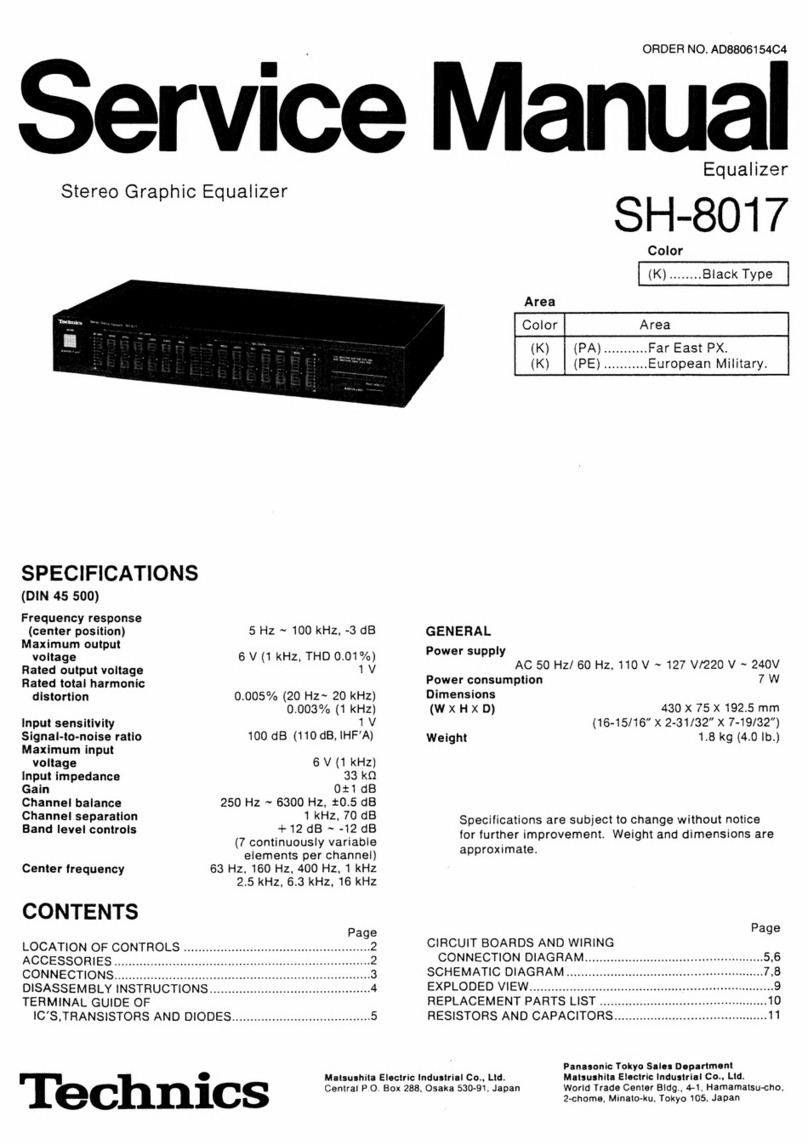
Technics SH-8017 User manual

Technics
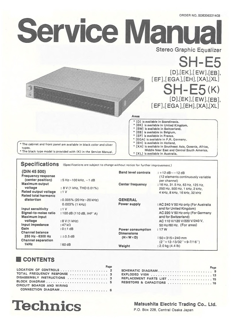
Technics SH-E5 User manual

Technics
Technics SH-DV280EG User manual

Technics
Technics SH-8065 User manual

Technics
Technics SH-DV250 User manual

Technics
Technics SH-EH50 User manual

Technics
Technics SH-DV290EG User manual

Technics
Technics SH-8055 User manual