manuals.online logo
Brands
  1. Home
  2. •
  3. Brands
  4. •
  5. Technics
  6. •
  7. Tuner
  8. •
  9. Technics Quartz ST-G7 User manual

Technics Quartz ST-G7 User manual

Other manuals for Quartz ST-G7

2

Other Technics Tuner manuals

Technics SA-EH750 User manual

Technics

Technics SA-EH750 User manual
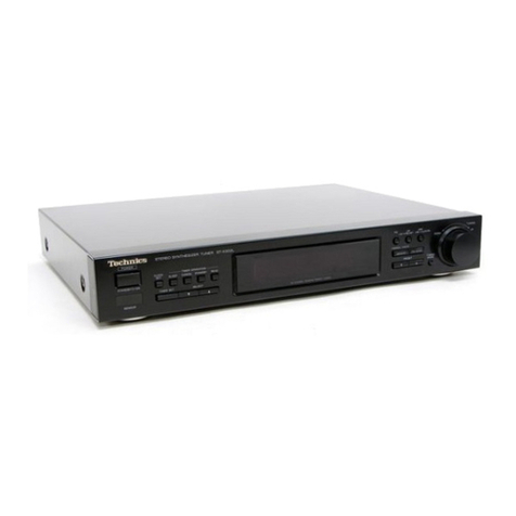
Technics ST-9030 User manual

Technics

Technics ST-9030 User manual

Technics ST-X302L User manual

Technics

Technics ST-X302L User manual
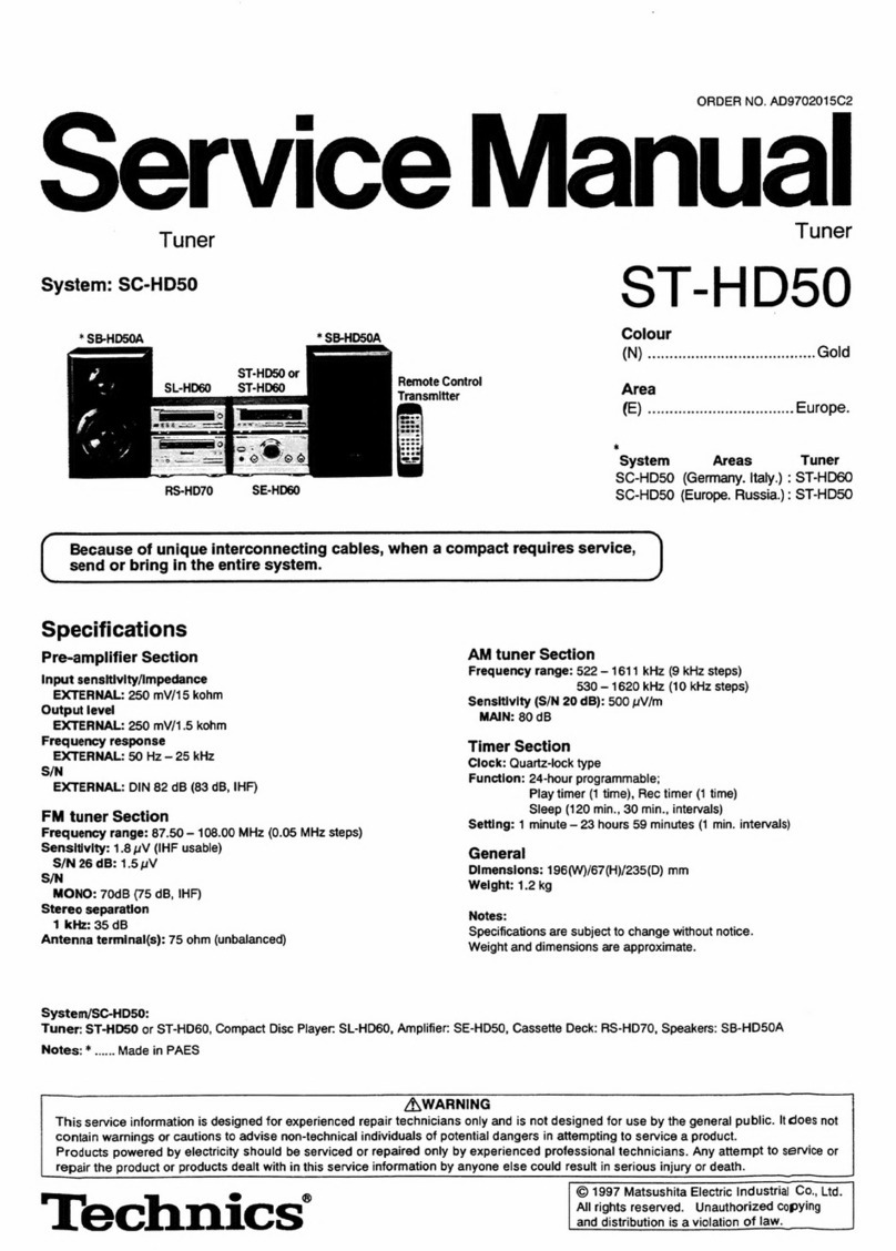
Technics ST-300 User manual

Technics

Technics ST-300 User manual

Technics ST-GT630 User manual

Technics

Technics ST-GT630 User manual

Technics ST-HD501 User manual

Technics

Technics ST-HD501 User manual

Technics ST-HD51 User manual

Technics

Technics ST-HD51 User manual

Technics Quartz ST-G45AL User manual

Technics

Technics Quartz ST-G45AL User manual

Technics ST-X302L User manual

Technics

Technics ST-X302L User manual

Technics ST-7600 User manual

Technics

Technics ST-7600 User manual

Technics ST-CH505 User manual

Technics

Technics ST-CH505 User manual

Technics SA-EH50 User manual

Technics

Technics SA-EH50 User manual

Technics ST-HD505 User manual

Technics

Technics ST-HD505 User manual

Technics ST-HD50 User manual

Technics

Technics ST-HD50 User manual
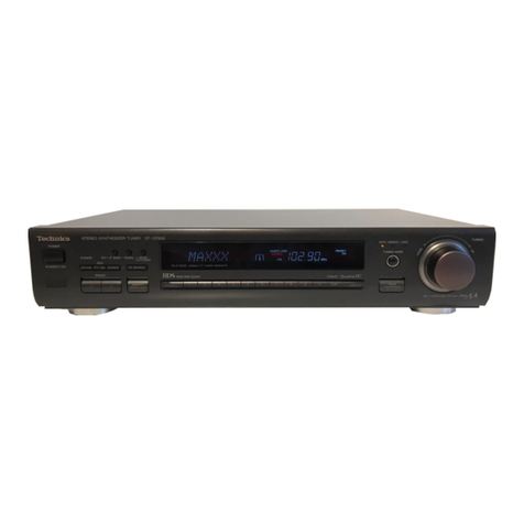
Technics ST-9038 User manual

Technics

Technics ST-9038 User manual

Technics ST-G570 User manual

Technics

Technics ST-G570 User manual

Technics Quartz ST-G7 User manual

Technics

Technics Quartz ST-G7 User manual

Technics ST-K50 User manual

Technics

Technics ST-K50 User manual

Technics ST-GT650 User manual

Technics

Technics ST-GT650 User manual
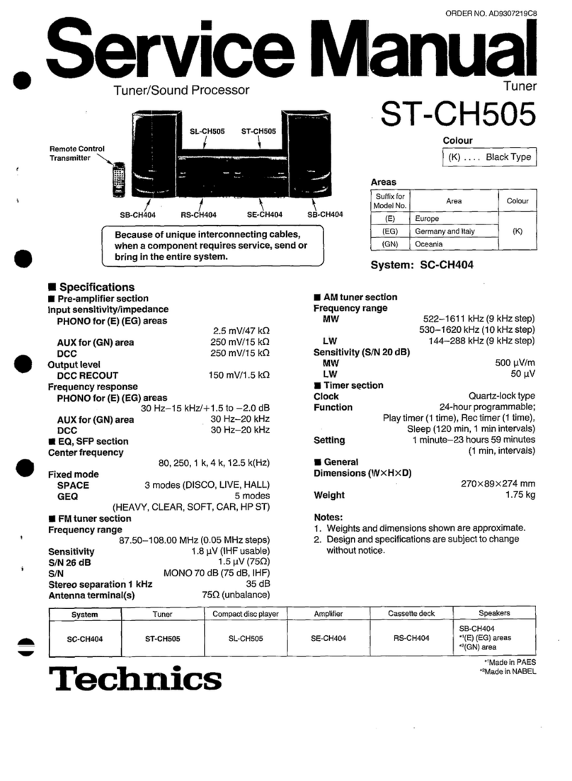
Technics ST-HD515 User manual

Technics

Technics ST-HD515 User manual

Technics ST-GT550 User manual

Technics

Technics ST-GT550 User manual

Technics ST-GT350 User manual

Technics

Technics ST-GT350 User manual

Technics ST-CH505 User manual

Technics

Technics ST-CH505 User manual
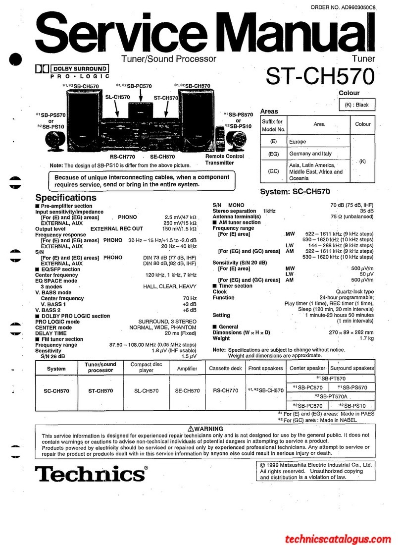
Technics ST-S2L User manual

Technics

Technics ST-S2L User manual

Popular Tuner manuals by other brands

Arcam DT91 Handbook

Arcam

Arcam DT91 Handbook

HDHomeRun 20121008 installation instructions

HDHomeRun

HDHomeRun 20121008 installation instructions

Eico HFT-92 instruction manual

Eico

Eico HFT-92 instruction manual

MFJ MFJ-928 instruction manual

MFJ

MFJ MFJ-928 instruction manual

Teac T-1D Service manual

Teac

Teac T-1D Service manual

NAD C 445 owner's manual

NAD

NAD C 445 owner's manual

Sony ST-SA5ES operating instructions

Sony

Sony ST-SA5ES operating instructions

Pioneer GEX-P700DAB Operation manual

Pioneer

Pioneer GEX-P700DAB Operation manual

Sirius Satellite Radio SC-FM1 user guide

Sirius Satellite Radio

Sirius Satellite Radio SC-FM1 user guide

Antique Automobile Radio 283501B Installation and operating instructions

Antique Automobile Radio

Antique Automobile Radio 283501B Installation and operating instructions

Sanyo FMT M15L Service manual

Sanyo

Sanyo FMT M15L Service manual

Monacor PA-1200R instruction manual

Monacor

Monacor PA-1200R instruction manual
Manhattan 176156 user manual

Manhattan

Manhattan 176156 user manual

Marantz ST-15S1 user guide

Marantz

Marantz ST-15S1 user guide

Korg HA-40 owner's manual

Korg

Korg HA-40 owner's manual

Pioneer XC-IS21T Service manual

Pioneer

Pioneer XC-IS21T Service manual

Harman Kardon TU915 Technical manual

Harman Kardon

Harman Kardon TU915 Technical manual

Tunersys WS16 1 quick start guide

Tunersys

Tunersys WS16 1 quick start guide

manuals.online logo
manuals.online logoBrands
  • About & Mission
  • Contact us
  • Privacy Policy
  • Terms and Conditions

Copyright 2025 Manuals.Online. All Rights Reserved.

ORDER
NO.
HAD84062801C9
Service
Manual
Tuner
CYUARTZ
Synthesizer
ST-G
A
FM/AM
Stereo
Tuner
eaten
|
(K)
...Black
Type
(S)...Silver
Type
SPECIFICATIONS
(DIN
45
500)
@
FM
TUNER
SECTION
87.50~108.00
MHz
87.525~108.025
MHz
(+25
kHz
shift)
Frequency
range
Sensitivity
1.2
uV
(IHF,
usable)
S/N
30
dB
1.1
pV
(75Q)
S/N
26
dB
1.0
pV
(75Q)
S/N
20
dB
0.9
wV
(75Q)
IHF
46
dB
stereo
quieting
sensitivity
28
pV/75Q
Total
harmonic
distortion
MONO
0.01%
STEREO
0.02%
Dynamic
range
116
dB
Frequency
response
4
Hz~18
kHz,
+0.2
dB~
—0.5
dB
Alternate
channel
selectivity
normal
+400
kHz
55
dB
super
narrow
+200
kHz
25
dB
Capture
ratio
1.0
dB
Image
rejection
at
98
MHz
105
dB
IF
rejection
at
98
MHz
110
dB
Spurious
response
rejection
at
98
MHz
110
dB
AM
suppression
70
dB
Stereo
separation
1
kHz
65
dB
10
kHz
50
dB
Carrier
leak
19
kHz —70
dB
38
kHz
—70
dB
Channel
balance
(250
Hz~6,300
Hz)
+1.0
dB
Limiting
point
0.75
pV
Technics
..
Scandinavia
and
Switzerland
...United
Kingdom
..
southeast
Asia,
Oceania,
Africa,
Middle
Near
East
and
Central
South
America
(K)(S)
|
[XL]
...Australia
(K)(S)
|
[EH]
...Holland
(K)(S)
|
[EB]
...Belgium
(K)(S)
|
[EF]
...France
(K)(S)
|
[PC]
...European
Audio
Club
(K)(S)
|
[PA]
...Far
East
PX
(K)(S)
|
[PE]
...European
Military
(K)(S)
|
[EGA]...F.R.
Germany
Bandwidth
IF
amplifier
180
kHz
FM
demodulator
1000
kHz
Antenna
terminals
75Q
(unbalanced)
@
AM
TUNER
SECTION
Frequency
range
(For
Europe,
South
Africa
and
Australia)
522~1629
kHz
(9
kHz-step)
530~1620
kHz
(10
kHz-step)
(For
Saudi
Arabia
and
others)
531~1620
kHz
(9
kHz-step)
530~1620
kHz
(10
kHz-step)
Sensitivity
(S/N
20
dB)
20
pV,
290
uV/m
Selectivity
(£9
kHz)
55
dB
Image
rejection
at
999
kHz
AO
dB
IF
rejection
at
999
kHz
65
dB
@
GENERAL
Output
voltage
0.6V
Power
consumption
11W
AC
50
Hz/60
Hz,
110V/120V/220V
/240V
430
xX
97
X
76mm
(16-15/16"
X
3-13/16”
x
1-7/8")
Weight
4.1
ky
@
Ib.)
Power
supply
Dimensions
(WxXHXD)
¢
Specifications
are
subject
to
change
without
noice
for
further
improvement.
*
Weights
and
dimensions
shown
are
approximate.
Panasonic
Tokyo
Matsushita
Electric
Industrial
Co.,
Ltd.
1-2,
1-chome,
Shibakoen,
Minato-ku,
Tokyo
105
Japan
Matsushita
Electric
Tradng
Co.,
Ltd.
P.O.
Box
288,
Centry
Osaka
Japan
m@
CONTENTS
Page
Page
SAFETY
PRECAUTION
..........
000
ee
eee
eee
2
FUNCTION
OF
LIQUID
CRYSTAL
PANEL............
16
FEATURES.
core
fe
Scobie:
Sa
a
heh
ay
eines
WTA
Eel
a
She BUA
he
2
WAVEFORMS:
2.2555.
cose
gi
5
BG
a
ok
Fhe
eG
wae
ws
Shei
ts
17
LOCATION
OF
CONTROLS............0+
00
eee
3,4
BLOCK
DIAGRAM
..........
02
e
eee
eee
18,19
HOW
TOOPERATE...........-02.-0
22
ee
eeeee
4~6
CIRCUIT
BOARDS
AND
WIRING
CONNECTION
BEFORE
REPAIR
AND
ADJUSTMENTS
.............
7
DIAGRAM
22.
ieie
8
fee
8
es
Ei
ea
ee
20
~
22
DISASSEMBLY
INSTRUCTIONS
...............-
7~9
SCHEMATIC
DIAGRAM
..........0
000
eee
23
~
28
HOW
TO
USE
THE
AMLOOP
ANTENNA
.............
10
TERMINAL
GUIDE
OF
TRANSISTORS,
IC’S
AND
MEASUREMENTS
AND
ADJUSTMENTS
.........
10
~
13
DIODES
5
i.e.
200
kee
eS
era
eh
ag
te
tera
Bee
aS
29,
30
FUNCTION
OF
TERMINAL
(MPX
IC301
-AN7471S)......
14
RESISTORS
AND
CAPACITORS
..............
29
~
31
FUNCTION
OF
TERMINAL
(PLL
CONTROLLER
IC902.
REPLACEMENT
PARTS
LIST..............245
31~
33
MIN
12919)
cece
seh
a
oe
oS
eee
ww
ee
Sse
st
eb
ees
eS
ete
14
EXPLODED
VIEW...
1.2...
ee
tt
te
es
33,
34
FUNCTION
OF
TERMINAL
(MICRO
COMPUTOR
!C903
-
MN1554STD)...
2.2...
2-0-0
eee
ee
15
m@
SAFETY
PRECAUTION
.
Before
servicing,
unplug
the
power
cord
to
prevent
an
electric
shock.
.
When
replacing
parts,
use
only
manufacturer’s
recommended
components
for
safety.
.
Check
the
condition
of
the
power
cord.
Replace
if
wear
or
damage
is
evident.
After
servicing,
be
sure
to
restore
the
lead
dress,
insulation
barriers,
insulation
papers,
shields,
etc.
.
Before
returning
the
serviced
equipment
to
the
customer,
be
sure to
make
the
following
insulation
resistance
test
to
prevent
the
customer
from
being
exposed
to
a
shock
hazard.
ORWNH
e
INSULATION
RESISTANCE
TEST
1.
Unplug
the
power
cord
and
short
the
two
prongs
of
the
plug
with
a
jumper
wire.
2.
Turn
on
the
power
switch.
3.
Measure
the
resistance
value
with
onmmeter
between
the
jumpered
AC
plug
and
each
exposed
metal
cabinet
part,
such
as
screwheads
antenna,
contro!
shafts,
handle
brackets,
etc.
Equipment
with
antenna
terminals
should
read
between
3MQ2
and
5.2MQ
to
all
exposed
parts.
(Fig.
A)
Equipment
without
antenna
terminals
should
read
approximately
infinity
to
all
exposed
parts.
(Fig.
B)
Note:
Some
exposed
parts
may
be
isolated
from
the
chassis
by
design.
These
will
read
infinity.
Antenna
terminal
Exposed
Exposed
metal
metal
part
part
Ohmmeter
Ohmmeter
(Fig.
A)
(Fig.
B)
Resistance
=
3MQ2—5.2MQ
Resistance
=
Approx
oo
4.
If
the
measurement
is
outside
the
specified
limits,
there
is
a
possibility
of
a
shock
hazard.
The
equipment
should
be
repaired
and
rechecked
before
it
is
returned
to
the
customer.
@
FEATURES
@
Newly
developed
LS!
successfully
incorporating
both
®@
Self-computing
RF
tuning
circuit
capable
of
receiving
digital
(signal
control)
and
analog
(linear
&
signal
trans-
desired
station
under
the
best
conditions.
Mission)
circuits
in
one
body.
@
FM-IF
automatic
IF
band
selecting
function.
@
Extra-wide
dynamic
range
of
116
dB
(1
kHz),
low
dis-
@
|nput/output
terminal
for
personal
computer
con
nection.
tortion
of
0.01%
{1
kHz),
and
stereo
separation
of
@
Multi-function
LCD
intensive
display.
65
dB
(1
kHz).
@
Reference
signal
0.33
kHz
record
checking
signa
!
Output
@
Linear
detector
and
linear
demodulation
digital
detector
Circuits,
function,
m
LOCATION
OF
CONTROLS
e
Front
Panel
Memory
indicator
Channel
display
Quartz-lock
/FM
muting
off
indicator
FM
stereo
indicator
Power
(
stand-by
-m
on)
©
Recording
level
check
FM
signal-strength
indicator
FM
IF
band
selector
@
FM
muting
off/scan
level
selector
FM
mode
selector
@
FM
IF
band
indicators
(FM
auto
IF)
normal
/a\:
This
indicator
will
illuminate
if
the
signal
is
strong
and
there
is
little
effect
from
interference.
super
narrow
/a\:
This
indicator
will
iluminate
if
the
signal
is
weak
and/or
there
is
interference.
The
illumination
of
the
left
and/or
right
parts
of
the
indicator
indicates
that
interference
waves
are
present
within
+300
kHz
(left:
-,
right:
+)
of
the
tuned
frequency.
@
FM
muting
off/scan
level
selector
(muting)
This
selector
is
used
when
releasing
the
FM
broadcast
muting
function
and
when
setting
the
scan
level
for
FM
broadcasts.
¢
Releasing
the
muting
function
(off)
In
mountainous
areas,
etc.,
where
broadcast
waves
are
weak,
breakup
in
the
sound
can
be
lessened
by
lightly
pressing
the
button.
When
this
is
done,
the
function
is
released
only
for
the
statin
being
received.
However,
when
a
tuning
button
is
pressed
to
begin
scanning,
the
former
scan
level
will
be
used.
©
Setting
the
scan
level
(scan
level)
This
level
setting
is
effective
only
for
the
automatic
preset
memory
and
auto
tuning.
When
the
button
is
held
down,
“dB”
will
be
displayed
and
the
numbers
30, 40,
and
50
will
be
displayed
in
order.
When
the
desired
level
is
reached,
release
the
button.
The
higher
the
level,
the
more
noise
is
reduced.
Stations
with
good
reception
can
use
“
a
high
level”,
but
stations
below
the
set
level
cannot
be
received.
In
order
to
receive
these
station,
the
level
has
to
be
reset.
no]
®
N
—
—
ae
2
c
®
E
o.
o
2%
.
nw
c
Ss
BS
1
~
a
=
oO
n
Station
Preset
tuning
(1
~
16)
(FM)
iaie
Band
selectors
Control
panel
door
release
©
Band
selectors
(band
selector)
FM:
Press
this
button
to
listen
to
an
FM
broadcast.
+25
kHz:
The
displayed
FM
frequency
can
be
shifted
by
+0.025
MHz
(+25 kHz)
in
order
to
precisely
align
with
the
frequency
of
the
FM
broadcast
station.
lf
the
FM
button
is
pressed
until
the
final
digit
of
the
frequency
display
is
a
small
“5”,
the
FM
frequency
will
shift
+0.025
MHz
(+25
kHz).
To
return
to
the
original
indication,
press
until
the
final
small
“5”
digit
disappears.
AM:
Press
this
button
to
listen
to
an
AM
broadcast.
allocation:
A
frequency
step
of
either
AM
9
kHz
or
AM
10
kHz
can
be
selected.
Set
to
the
appropriate
position
for
your
locality.
When
the
AM
button
is
pressed
slightly
longer
and
then
released
when
the
AL10”
indication
illuminates,
the
AM
frequency
“step”
will
change
to
10
kHz.
To
return
to
the
original
9
kHz,
press
the
AM
button
slightly
longer,
and
then
release
it
when
the
“AL9”
indication
illuminates.
©
Recording-level
check
button
(rec
level)
This
button
is
to
be
used
for
adjustment
of
the
recording
level
when
recording
an
FM
broadcast.
When
this
button
is
pressed,
the
microcomputer
functions
to
emit
a
reference
signal
of
precisely
333
Hz
from
the
output
terminals
of
this
unit.
The
word
“CAL”
(calibration)
and
then,
soon
thereafter,
“0.33
kHz”
will
be
shown
by
the
digital
display.
Adjustment
of
the
recording
level
Use
the
input-level
control(s)
of
the
tape
deck
to
make
the
adjustment
while
watching
the
recording-level
meters.
e
For
VU
meters
and
level
meters:
Adjust
so
that
the
indication
is
about
+2
VU
or
+2
dB.
e
For
peak-level
meters:
Adjust
so
that
the
indication
is
about
—2
dB.
Notes:
1)
Because
the
ideal
recording
level
is
apt
to
vary
depending
upon
the
program
source
and
the
characteristics
of
the
tape
deck,
the
adjustment
should
be
made
by
also
considering
those
factors.
2)
Don't
press
the
operation
buttons
of
this
unit
during
a
recording.
If
they
are
pressed,
the
recorded
soundmay
be
disturbed.
e
Rear
Panel
Control
input
terminal
Output
terminal
r—Computer
control
terminal
Voltage
selector
(AC
110/120/220/240V)
AC
inlet
(Except
[EGA,
XA]
areas)
Main
power
(Moff,
-mon)
AM
loop
antenna
terminal
AM
antenna
terminal
FM
antenna
terminal
(750,
coaxial)
m
HOW
TO
OPERATE
e
Listening
to
radio
broadcasts
Important!
This
antenna
must
be
installed
ifj
i
isteni
to
receive
AM
broadcasts.
Turn
the
amplifier
on,
and
prepare
it
for
listening
to
radio
AM
Isopcantenia
broadcasts.
Station
selection
by
using
the
tuning
buttons:
@
Press
either
“FM”
or
“AM”:
@
Press
the
left
button
to
change
the
frequency
downward,
and
press
the
right
button
to
change
the
frequency
upward.
&
Adjustment
to
FM
broadcast
signal
e
Auto
tuning
strength
is
possible
for
automatic
Press
the
button.
When
the
i
fre
indication
begi
tuning.
bes!
requency
eginsto
Press
and
hold
the
button
change,
release
the
button
(a
(Will
change
to
dB
indication
}
broadcasting
station
will
be
Release
the
button
when
the
desired
selected
automatically).
.
scan
level
indication
(30,
40
or
50
dB)
Repeat
this
operation
until
the
is
displayed
desired
station
is
found.
(When
the
scan
level
is
set,
it
will
return
e
Manual
tuning
to
frequency
display.)
Press
the
button
momentarily
wv
(the
frequency
will
change
«((
each
time
the
button
is
pressed)
and
tune
to
the
desired
station.
YS
Power:
“on”
(am
)
Technics
(uw
sytnesize
FMAM
Stereo
Tuner
87-07
;
+
stereo
quarts
oon
/FAt
mating
oft
“
He
tina
satector
|b
ae
|
FO
|
i
i
—————
|
own
wo
a
Bang
ee
mernory
C=
Station
selection
by
using
preset
tuning
buttons:
©
To
select
the
front
channels
(CH
1~8):
*°
To
select
the
back
channels
(CH
9~16):
Press
Frequency
stored
in
the
Press
momentarily.
memory
and
channel
number
slightly
longer.
are
displayed.
A
|
Frequency
stored
in
the
memory
and
channel
number
are
displayed.
e
How
to
preset
radio
broadcast
frequencies
Important!
This
antenna
must
be
installed
to
receive
AM
broadcasts.
AM
loop
antenna
e
Manual
memory
presetting
Stations
can
be
freely
preset
to
any
desired
channel.
This
unit
is
used
to
preset
as
many
as
16
radio
broadcast
frequencies:
FM/AM
random
presetting.
After
broadcast
fre-
@
Before
memory
presetting
Each
button
is
used
to
preset
two
stations.
quencies
have
been
preset
as
described
below,
any
desired
station
can
be
quickly
and
easily
selected
by
simply
touching
one
button.
Presetting
front
channels
(CH
1~8)
@
Memory
presetting
at
There
are
two
types
of
memory
presetting:
automatic
and
¢
Press
manual.
Select
whichever
is
preferred.
momentarily.
e
Automatic
memory
presetting
Beginning
at
the
frequency
indicated
by
the
digital
display,
the
FM
broadcasting
stations
and
AM
broadcasting
stations
will
be
automatically
preset
to
“channels”
1
through
16
for
FM
and
9
through
16
for
AM,
respectively.
Note
that
in
mountainous
or
remote
areas,
broadcasting
stations
which
have
weak
broadcasting
signals
cannot
be
Q
Press
the
appropriate
tuning
button
to
tune
to
the
desired
broadcast:
Presetting
back
channels
(CH
9~16)
Press
slightly
e
Auto
tuning
Press
the
button.
When
the
frequency
indication
begins
to
change,
release
the
button
(a
broadcasting
station
will
be
selected
automatically).
Repeat
this
e
Manuai
tuning
wt
Press
the
button
momentarily
and
tune
to
u(
the
desired
station
(the
frequency
will
change
each
time
the
button
is
pressed).
operation
until
the
desired
station
is
found.
Adjustment
to
FM
broadcast
signal
strength
is
possible
for
automatic
tuning.
Press
and
hold
the
button.
(Will
change
to
dB
indication.)
Release
the
buiton
when
the
desired
scan
level
indication
(30,
40
or
50
dB)
is
displayed.
(When
the
scan
level
is
set,
it
will
return
to
frequency
automatically
preset
into
the
memory.
a
Power:
“on”
(
B--m=
)
Adjustment
to
FM
broadcast
signal
strength
is
possible.
Press
and
hold
the
button.
(Will
change
to
dB
indication.)
Release
the
button
when
the
desired
scan
level
indication
(30,
40
or
50
dB)
is
displayed.
(When
the
scan
level
is
set,
it
will
return
to
frequency
display.)
A
broadcast
signal
stronger
than
the
set
level
is
memorized.
@
Press
the
“FM”
or
“AM”
button:
To
change
the
AM
frequency
by
10
kHz:
Press
the
“AM”
button
slightly
longer
and
release
the
button
when
the
“AL
10”
is
displayed.
wo
PM/AM
random
ch
preset
tuning
:
a
display.)
Power:
“on”
(
Bm
)
@
Press
the
“FM”
or
“AM”
button.
To
change
the
AM
frequency
by
10
kHz:
Press
the
“AM”
button
slightly
longer
and
release
the
button
when
the
“AL
10”
is
displayed.
Memory
indicator
|
Casein:
Syrtnemiver
FM/AM
Stereo
Tuner
8-4
ert
cK/F
MM
mang
off
ni
me
ci
Cy
-_
FM/AM
fandom
i6ch
praset
tuning
~
digest
Ate
oe
16
aid
%
=
or)
Confirm
the
names
(call
signs,
etc.)
of
the
broadcasting
stations
which
are
preset
to
each
channel,
and
enter
them
on
the
station
memory
file
sheet.
To
check
the
front
channels
(CH
1~8):
Press
Frequency
stored
in
the
momentarily.
memory
and
channel
number
ley
Press.
When
the
frequency
indication
begins
to
change,
release.
While
the
memory
indicator
is
illuminated,
press
the
button
of
the
desired
channel.
Press
momentarily,
and
then
release.
(The
memory
indicator
will
beg
are
displayed.
A
To
check
the
back
channels
(CH
9~16):
Frequency
stored
in
the
order.
Press
slightly
longer.
memory
and
channel
number
are
displayed.
(The
frequency
will
change
upward,
and
the
automatic
presetting
will
begin
with
the
broadcasting
station
of
the
lowest
frequency
and
will
continue
in
Note
that
the
channel
display
illuminates
each
time
a
broadcast
station
is
preset
in
the
memory,
thus
indicating
which
“channel”
has
been
preset.)
7
t
D2
on]
My
(4)
©
To
preset
FM
broadcasting
stations:
Set
to
87.50
MHz.
®
Topreset
AM
broadcasting
stations:
Set
to
522
kHz
(or
530
kHz).
@
Press
the
button
and
hold
slightly
(frequency
will
change
continuously).
@
Release
it
at
87.50
MHz
for
FM
or
522
kHz
(or
530
kHz)
for
AM,
and
then
press
the
button
again
momentarily
(frequency
change
will
stop).
@
Press
the
button
momentarily
(frequency
will
change
each
time
the
button
is
pressed),
and
tune
to
one
of
the
above
frequencies.
©
To
preset
channels
1
through
8:
x
Press
the
button
momentarily,
and
then
Ci
release.
(Preset
channel
number
is
displayed
on
the
channel
display.)
©
To
preset
channels
9
through
16:
-
ae
Press
the
button
slightly
longer,
and
then
release.
(Preset
channel
number
is
displayed
on
the
channel
display.)
When
the
button
is
pressed,
the
memory
indicator
illumination
will
stop,
and
the
presetting
is
complete.
Note:
1.
If
the
memory
indication
illumination
stops
before
you
press
the
button,
once
again
repeat
step
(5)
and
then
step
(6).
2.
If
a
new
broadcasting
station
is
preset
into
a
channel,
the
broadcasting
station
which
was
previously
entered
in
that
channel
will
be
automatically
erased.
illuminate
for
approximately
4
seconds.)
4
A
Note:
If
the
button
is
pressed
continuously,
the
frequency
will
begin
to
change,
and
the
memory
will
be
preset
automatically.
To
stop
the
automatic
memory
presetting,
once
again
press
either
the
“up”
button
or
the
“down”
button.
7)
Enter
the
name
(call
sign,
etc.)
of
the
preset
broad-
casting
station
on
the
station
memory
file
sheet.
This
completes
the
procedures
for
presetting
radio
broad-
cast
frequencies.
The
other
preset-tuning
butfons
can
be
preset
in
the
same
way
by
following
steps
(2)
through
(7).
ST-G7
ST-G7
m
BEFORE
REPAIR
AND
ADJUSTMENT
The
power
switch
of
this
unit
is
located
on
the
secondary
side
of
power
transformer.
So,
be
sure
to
disconnect
the
power
cord
from
the
socket
before
starting
the
repair
work.
Also,
when
repairing
the
digital
circuit,
discon-
nect
the
power
cord
and
then
short-circuit
across
the
gold
capacitors
(C920,
C921,
2.3
V
3.3F)
with
a
resistor
(10
ohms,
about
1
W)
to
discharge
the
voltage.
m
DISASSEMBLY
INSTRUCTIONS
ee]
How
to
remove
the
cabinet
|
How
to
remove
the
bottom
board
Procedure
2
@
Remove
the
11
setscrews.
(Q@~
@)
Front
pane}
Cabinet
Rear
panel
1.
Pull
out
the
5
connectors.
(J8,
J9,
J11
and
2
lamp
con-
nectors)
2.
Remove
the
7
setscrews.
(Q@~
@)
3
Procedure
1=3
Connector
terminals
(J8,
J9,
J11)
as
viewed
from
above
with
cabinet
removed,
Lamp
connectors
for
LCD
J11\,
3g
|
\
\
im)
9
A
ay
7)
Front
panel
Bottom
board
@
Remove
the
8
setscrews.
(Q@~
@)
ae
No.
How
to
remove
the
sub
panel
Procedure
1=>3=p4
1.
Remove
the
2
setscrews.
(@,
@)
2.
Remove
the
lamp
case
and
liquid
crystal
panel
P.C.B.
Front
panel
Liquid
crystal
panel
P.C.B.
:
Z
|
Liquid
crystal!
|
panel
P.C.B.
Procedure
1939495
1.
Remove
the
ornament.
2.
Remove
the
4
setscrews.
(Q@~
@)
3.
Remove
the
3
setscrews.
(@
~
@)
Switch
P.C.B.
Selector
button
Ref.
No.
6
How
to
remove
the
LCD
panel
@
Remove
the
1
setscrew.
(@)
Procedure
1—>3m>6
1,
Remove
the
2
setscrews
(@
,@)
3)
LCD
panel
receptacle
2.
Remove
the
lamp
case
and
liquid
crystal
panel
P.C.B.
Filter
Front
panel
Bracket
Lamp
a
Oe
ay
Liquid
crystal
panel
P.C.B.
@
Remove
the
diffusion
plate
and
liquid
crystal
panel
ins
How
to
remove
the
glass
door
P.C.B.
from
the
LCD
panel
receptacle.
Flat-head
screwdriver
LCD
panel
Procedure
a
LCD
panel
1.
Remove
the
4
setscrews.
(@~@)
receptacle
1=> 3
=>7
conalive
rubber
2.
Turn
the
glass
door
hinge
counter-
clockwise
((
).
3.
When
disassembling
or
assembling
the
movable
bodies
A
&
B,
apply
GREASE
6
to
the
parts
shown
in
@
~@.
Liquid
crystal
panei
P.C,B,
Conductive
rubber
Diffusion
plate
Front
panel
Caution:
Never
touch
the
LCD
panel,
electrode,
conductive
rubber
and
liquid
crystal
panel
P.C.B.
electrode
with
bare
hand.
(Movable
body
8)
@
Apply
GREASE
6
to
these
parts.
@
Apply
GREASE
6
to
these
parts.
m
HOW
TO
USE
THE
AM
LOOP
ANTENNA
Find
the
best
reception
position
for
the
FM
antenna,
and
then
fix
2.
When
attaching
the
antenna
to
the
rack.
it
in
place
ona
wail,
the
rack,
or
the
unit.
AM
antenna
holder
(A)
(included)
Pay
attention
to
the
following
points
when
attaching
the
antenna.
1)
Find
the
height
and
direction
of
the
antenna
where
reception
is
best
and
then
fix
it
vertically
to
the
wail,
rack,
etc.
2)Do
not
attach
it
horizontally
(to
do
so
would
impair
reception).
3)
Do
not
attach
it
close
to
meta!
surfaces,
power
cords,
or
speaker
wires
(to
do
so
would
result
in
noise).
4)
Do
not
attach
it
close
to
a
tape
deck
(when
the
tape
deck
is
being
used,
chirping
or
beeping
sounds
may
be
received).
3.
When
attaching
the
antenna
to
the
unit.
AM
antenna
holder
(B)
(included)
a
CK
Rear
panel
AM
loop
antenna
1.
When
attaching
the
antenna
to
a
wall,
column.
of
the
unit
<~
(included)
AM
loop
antenna
(included)
4.
If
a
hook
is
used
(if
the
holder
can’t
be
attached
by
screws)
Hook
(option)
AM
antenna
holder
(A)
(included)
AM
loop
antenna
(included)
m
MEASUREMENTS
AND
ADJUSTMENTS
AM
ADJUSTMENT
*
Setting
and
Equipment
used
1.
ACelectronic
voltmeters
(EVM).
5.
Output
of
signal
generator
should
be
no
higher
than
necessary.
2.
AMsignal
generator
(AM-SG).
to
obtain
an
output
reading.
3.
Set
Band
selector
to
‘AM
(allocation
9
kHz)’’
position.
6.
Use
a
non-metal
screwdriver
for
the
adjustment.
4.
Maintain
line
voltage
at
rated
voltage.
AM
SIGNAL
GENERATOR
DISPLAY
FREQUENCY
PREPARATIONS
PARTS
ADJUSTED
ADJUSTING
PR
OCEDURE
CONNECTION
FREQUENCY
Step
No.
AM-IF
ADJUSTMENT
Connect
AM-SG
to
AM
antenna
terminal
*
Adjust
the
input
frequency
through
200pF
aoe
is
Prequeniey
of
|
Connect
AC
EVM
or
T7201
(AM
1
st
IFT)
and
adjustment
points
so
:
%
Mod,
non-inter-
scope
to
“OUTPUT
capacitor.
Common
to
with
400
Hz)
ference
terminals
that
the
output
becomes
1
chassis.
(Powerful
input)
:
maximum,
(Refer
to
Fig.
1)
AM-RF
ADJUSTMENT
|
Except
[XA]
area
522
kHz
eating
[XA]
Connect
AC
EVM
or
1.
Adjust
for
max
imum
output,
2
[XA]
area
522
kHz
scope
to
“OUTPUT”
L203
(ANT
Coil)
2.
Adjust
core
of
L203
by
531
kHz
terminals.
screwdriver.
(30%
Mod,
Lees
Connect
AM-SG
to
with
400
Hz)
|
991
zl
i
oeoeee
612
kHz
Connect
AC
EVM
or
1,
Adjust
for
max
imum
output.
3
eapscny
Caomimon'to
(30%
Mod.
612
kHz
scope
to
“OUTPUT”
L202
(ANT
Coil)
2.
Adjust
core
of
L202
by
chassis
(Weak
input)
with
400
Hz)
terminals.
screwdriver,
(Refer
to
Fig.
1)
1.
Adjust
for
max
imum
output.
1503
kHz
Connect
AC
EVM
or
cT201
2,
Repeat
steps
(2,
3)
and
(4)
4
(30%
Mod.
1503
kHz
scope
to
“OUTPUT”
(ANT
Trimmer)
until
the
frequency
correctly
with
400
Hz)
terminals.
matches
the
frequency
display.
adjustment.
[FM
ADJUSTMENT
*
Setting
and
Equipment
used.
*
Preparation
of
FM
signal
generator
(FM-SG)
1.
FM
signal
generator
(FM-SG),
1.
The
standard
input
of
the
set
is
60
dB
(1
mV),
400
Hz,
100%
2.
Distortion
analyser.
modulation
(Because
of
attenuation,
using
coaxial
cables,
SG
3.
Oscilloscope
output
must
be
6
GB
plus,
That
is,
when
input
60
dB
SG
4.
AC
and
DC
electronic
voltmeters
(EVM).
output
is
to
be
66
dB.)
5.
Frequency
counter
(19
kHz
and 108
MHz
measurable).
6.
Set
band
selector
to
‘‘FM"
position.
7.
Set
FM
mode
selector
to
““mono”
position.
*
When
the
frequency
is
changed,
muting
is
automatically
turned
on.
8.
Other
setting
are
the
same
as
in
AM
adjustment.
So,
be
sure
to
turn
it
off
by
the
FM
muting
off/scan
level
selector
switch,
9.
Set
IF
band
selector
to:
‘‘normal”
position.
Also,
make
sure
that
the
FM
IF
band
is
at
“‘normal’’.
=
FM
SIGNAL
GENERATOR
DISPLAY
PREPARATIONS
PARTS
ADJUSTED
ADJUSTING
PROCEDURE
CONNECTION
FREQUENCY
|
FREQUENCY
rbd
FM
MONO
DISTORTION
ADJUSTMENT
100.10
MHz
Connect
DC
VEM
1.
Adjust
T101
core
so
that
m
between
PGA
and
set
tile
voltage
measured
in
signal
5
pirates
100.10
MHz
through
choke
T101
{Discri.
IFT)
mode
is
0
mV
in
300
mV
wilt
#
coil.
(Refer
to
Fig.
2)
range.
Connect
FM-SG
to
100.10
MHz
i
|
Connect
AC
EVM
1.
Adjust
for
maximum
output.
,
a
:
Bi)
martene
carried.
Oe
Me
|
doasianare:
«|
Poteet
MMMM
2m
Irie
Sea
fray
|
abet
care
ch
102
ty
antenna
terminal.)
(Refer
to
Fig.
3)
Connect
DC
VEM
1.
Adjust
VR102
so
that
100.10
MHz
VR102
:
7
(0%
Mod.
100.10
MHz__|
Petween
(Pulse
count
duty
voltage
measured
in
with
400
Hz)
and
ground,
adj.)
signal
mode
isO
mV
in
(Refer
to
Fig,
4.)
J.
300
mV
range.
Short-circuit
between
MGW
and
by
jumper
wire
only
during
FM-RF
adjustment,
FM-RF
ADJUSTMENT
and
be
sure
to
open
the
circuit
during
adjustment
other
than
FM-RF.
1,
Scat
sc
Rey
5
EGET
and
bE
by
Seem,
|
areata
brow
ve
Bos
8
referririg
to’
Eid:
5
(100%
Mod,
87.50
MHz
2.
Connect
DC
EVM
L6
(OSC
Coil)
reading
on
DC
EVM.
19
g.
©.
with
400
Hz)
between
fiGAI
(+)
(Weak
input)
and
Ground.
LIOANT
Coil}
|
1+
Adel
woak
input
ee
that
90.10
MHz
L1
(ANT
Coil
cm
|
(100%
Mod.
|
90.10MHz
|
sgcyepysrserminals,
|
L3.
(ANT
Coil)
apd
auicald
acl
g
|
Connect
FM-SG
to
with
400
Hz)
erminals.
|
1a
(ANT
Coil)
2.
Make
the
adjustment
so
that
antenna
terminal
T1
(FM
1st
IFT)
the
output
wave
form
is
ver-
referring
to
Fig.
6.
tically
symmetrical.
(Fig.
7).
(Weak
input)
Tea
+
3.
Hepes!
ihestps
(8),
(9}
and
:
2
10)
until
the
frequency
cor-
10
(100%
Mod.
106.10
MHz
Tent
ea
CT1
(OSC
Trimmer)
rectly
matches
the
frequency
with
400
Hz)
‘
display.
PILOT
CANCEL
ADJUSTMENT
Connect
FM-SG
to
FM
antenna
terminal
100.10
MHz
: :
Make
the
adjustments
so
that
‘ :
Connect
scope
L301
(Pilot
filter)
F
11
referring
to
Fig.
8.
(0%
Mod.
:
the
output
waveform
is
(Apply
60
dB
to
with
400
Hz)
100.10
MHz
between
and
VR103
(Pilot
Cancel)
|
i
pelscring
se
antenna
terminal.)
(L+R)
Ground.
Fig.
9.
(Pilot
10%
Mod.
stereo
signal.)
L
ess
+
STEREO
DISTORTION
ADJUSTMENT
Connect
FM-SG
to
T
FM
antenna
terminal
100.10
MHz
Connect
distortion
refferring
to
Fig.
10.
(90%
Mod
analyser
to
“OUTPUT”
FE
Adjust
T1
and
T103
core
so
that
12
(Apply
60
dB
to
ith
ps
Hj
)
100.10
MHz
terminals
of
the
set
EM
clea
distortion
of
right
and
left
antenna
terminal.)
iL
or
R
mites
through
low-pass
filter.
7
channels
are
minimized.
(Pilot
10%
Mod.
(fc
=
15
kHz~19
kHz)
stereo
signal.)
ST-G7 ST-G7
Note:
FM
IFT
(2nd)
[T102],
FM
2
nd
IF
filter
[T104,
T105]
and
FM
DET
filter
[L302,
L303]
have
been
already
adjusted,
and
require
no
FM
SIGNAL
GENERATOR
:
EHeQUENCcY
|
PREPARATIONS
||
PARTS
ADJUSTED
|
ADJUSTING
PROCEDURE
2.3.
CONNECTION
FREQUENCY
FM
Signal
gene
tep
=
No.
SEPARATION
ADJUSTMENT
KS
Connect
EM-SG
to
1.
Adjust
VR303
so
that
R
:
output
is
minimized
when
(750)
Bete
aay
100.10
MHz
Sd
eac
ta
sede
stereo
modulator
is
in
L
e
OO
pone
(90%
Mod.
VR303,
VR304
(L
ch.
modulation)
mode,
13
{Apply
60
dB
to
antenna
f
100.10
MHz
of
the
set
through
: °
ermine
with
1
kHz)
lowe-bese
titer
(Separation)
2.
Adjust
VR304
so
that
L
(Pilot
10%
Mod
Reta
rupae!
(fo
=
15
kHz
~19
kHz)
SutoMs
etnies
Wien
stereo
signal.)
stereo
modulator
is
in
:
R
(R
ch
modulation)
mode.
SIGNAL
STRENGTH
LEVEL
ADJUSTMENT
1
1.
Change
LCD
display
from
.
ee
frequency
to
dB
by
pressing
onnect
-SG
to
the
FM
signal
button,
:
FM
antenna
terminal.
100.10
MHz
VR101
2.
Adjust
VR101
so
that
50
dB
FM
Signal
gener
14
(Apply
50
dB
to
(30%
Mod,
100.10
MHz
(Signal
strength
<
indicated
antenna
terminal.)
with
400
Hz)
level)
3.
Make
sure
that
the
signal
bh
strength
level
is
22
~
38
dB
when
the
input
is
30
dB.
(750)
ff
e
OO
e
Adjustment
points
612
kHz
1503
kHz
19
kHz
R—-L
L-R
FM
AM
ANT
AM
ANT
Filter
separation
separation
discri.
IFT
coil
trimmer
FM
Signal
gene
L301]
R304]
[VR303]
Computer
Control
Output
|
AM
ANT
control
input
terminal),
"
EXT
AC
inlet
terminal
terminal
——,
{|
Loop
L302
NO
ADJUSTMENT
L303
NO
ADJUSTMENT
ADJUSTMENT
T1085
NO
TPI03
Ground
point
450
kHz
FM
ANT
(75Q)
[vRI03
[ti03]
[vrioi}]
[t2o]
[ctr]
19
kHz
Pulse
count
FM
IFT
Signal
strength
AMIFT
FM
1st
FM
1
st
cancel
adj.
duty
adj.
(3
rd)
level
adj.
(1
st)
Osc.
OSC
coil
trimmer
AM
Signal
generator
(AM-SG)
r
oO
O'
0
°
OC
AM
antenna
terminal
7
Output
aad
terminal
Capacitor
(200pF)
[Fig.
1]
[Abb.
1]
Oscilloscope
me
FM
ANT
@
S
coil
{
L10
|
‘iz
|
|
AM
RF
coil
L203}
522kHz
FM
ANT
coil
T
coil
T
coil
FM
Signal
gener:
BR
'
adjusted,
and
require
no
|,
400
Hz,
100%
axial
cables.
SG
t60dB
SG
omatically
turned
on.
ff/scan
level
selector
switch.
ormal’’.
\DJUSTING
PROCEDURE
Adjust
T101
core
so
that
voltage
measured
in
signal
mode
is
O
mV
in
300
mV
range.
Adjust
for
maximum
output.
Adjust
core
of
T103
by
screwdriver.
Adjust
VR102
so
that
voltage
measured
in
signal
mode
is
O
mV
in
300
mV
range.
Adjust
L6
for
3.0V
reading
on
DC
EVM.
Add
weak
input
so
that
noise
is
included
in
the
output
wave
form,
Make
the
adjustment
so
that
the
output
wave
form
is
ver-
tically
symmetrical.
(Fig.
7).
Repeat
the
steps
(8),
(9)
and
(10)
until
the
frequency
cor-
rectly
matches
the
frequency
display.
ike
the
adjustments
so
that
>
output
waveform
is
nimum
referring
to
y.
9,
just
T1
and
T103
core
so
that
tortion
of
right
and
left
annels
are
minimized,
Step
No.
13
14
Control
Output
|
AM
ANT
/FM
ANT
input
terminal
Loop
EXT
(75)
terminal
-—
—
=
FM
ANT
@
S
coil
a
mzsr|
|
AM
RF
coil
L302
NO
ADJUSTMENT
Oa
lak
L203]
522kHz
Z)
L303
NO
FM
ANT
coil
ADJUSTMENT
Computer
control
AC
inlet
terminal
T105
NO
ADJUSTMENT
ADJUSTMENT
Mae
Ground
point
450
kHz
|
T201
19
kHz
Pulse
count
FM
IFT
Signal
strength
AM
IFT
FM
1
st
FM
1
st
cancel
adj,
duty
adj.
(3rd)
level
adj.
(1
st)
OSC.
OSC
coil
trimmer
AM
Signal
generator
(AM-SG)
Oscilloscope
AM
antenna
terminal
¢
Output
oe
terminal
Capacitor
{200pF)
[Fig.
1]
[Abb.
1]
DC
EVM
i
FM
SIGNAL
GENERATOR
DISPLAY
Cc
Oscilloscope
FREQUENCY
PREPARATIONS
PARTS
ADJUSTED
ADJUSTING
PROCEDURE
—
CONNECTION
FREQUENCY
FM
Signal
generator
(FM-SG)
“6
ae
SEPARATION
ADJUSTMENT
TEK
I
=
1.
Adjust
VR303
so
that
R
Connect
FM-SG
to
te
Te
at
ae
|
FM
antenna
terminal
Connect
AC
EVM
to
output
is
minimized
when
i730)
:
:
100.10
MHz
i
i
:
stereo
modulator
is
in
L
referring
to
Fig.
11.
(90%
Mod.
erat
Pit
oe
ena
u
G04
(L
ch.
modulation)
mode.
(Apply
Poe
RMEPNE
|
nthe
KHz)
Pa
ee
(Separation)
2.
Adjust
VR304
so
that
L
4-68
sees
tees
oe
Mod.
(L
or
R
mode)
(fe
=
15
kHz
~19
kHz}
ee
FEM
antenna
_(SLOx10!-20)
FM
antenna
terminal
(750)
stereo
signal.)
R
(R
ch
modulation)
mode
terminal
(750)
Fig.
3
Abb.
3
as
ls
:
[Fig.
2]
[Abb.
2]
[Fig.
3]
[ ]
SIGNAL
STRENGTH
LEVEL
ADJUSTMENT
1.
Change
LCD
display
from
DC
EVM
frequency
to
dB
by
pressing
pra
Connect
FM-SG
to
the
FM
signal
button.
.
EM
antenna
terminal.
aaa
ree
i
cee
2.
Adjust
VR101
so
that
50dB|
FM
Signal
generator
(FM-SG)
FM
Signal
generator
(FM-SG)
(Apply
0
dB
to
oa
aed
Hz)
3
‘eet
g
is
indicated.
©
antenna
terminal.)
3.
Make
sure
that
the
signal
strength
level
is
22
~
38
dB
TP302
&
ee
ee
|
ees
when
the
input
is
30
dB.
Z
Ground
Ground
‘eae
eee
FM
antenna
terminal
(75)
on
antenna
terminal
Q)
Adjustment
points
[Fig.
4]
[Abb.
4]
612
kHz
1503
kHz
{Fig.5]
[Abb.
5]
19
kHz
R-L
L-—R
FM
AM
ANT
AM
ANT
Filter
separation
separation
discri.
IFT
coil
trimmer
FM
Signal
generator
(FM-SG)
.
Noise
Tior
|
L202]
[er201
Oscilloscope
kar
ee
Output
goo
dO:
terminal
FM
antnna
terminal
(752)
[Fig.
6]
[Abb.
6]
Noise
AF
output
wave
form
[Fig.
7]
[Abb.
7]
Oscilloscope
FM
Signal
generator
(FM-SG)
pee
agett
[Fig.
9]
[Abb.
9]
FM
antenna
terminal
(750)
[Fig.
8]
[Abb.
8]
FM
Signal
generator
(FM-SG)
Distortion
analyser
Output
B
O°
OD
terminal
FM
antenna
terminal
(752)
[Fig.
10]
[Abb.
10]
Low
pass
filter
FM
Signal
generator
(FM-SG)
ACEVM
ACEVM
FM
antenna
terminal
(7522)
[Fig.
11]
[Abb.
11]