manuals.online logo
Brands
  1. Home
  2. •
  3. Brands
  4. •
  5. Technics
  6. •
  7. Tuner
  8. •
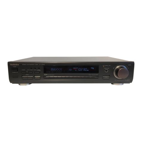
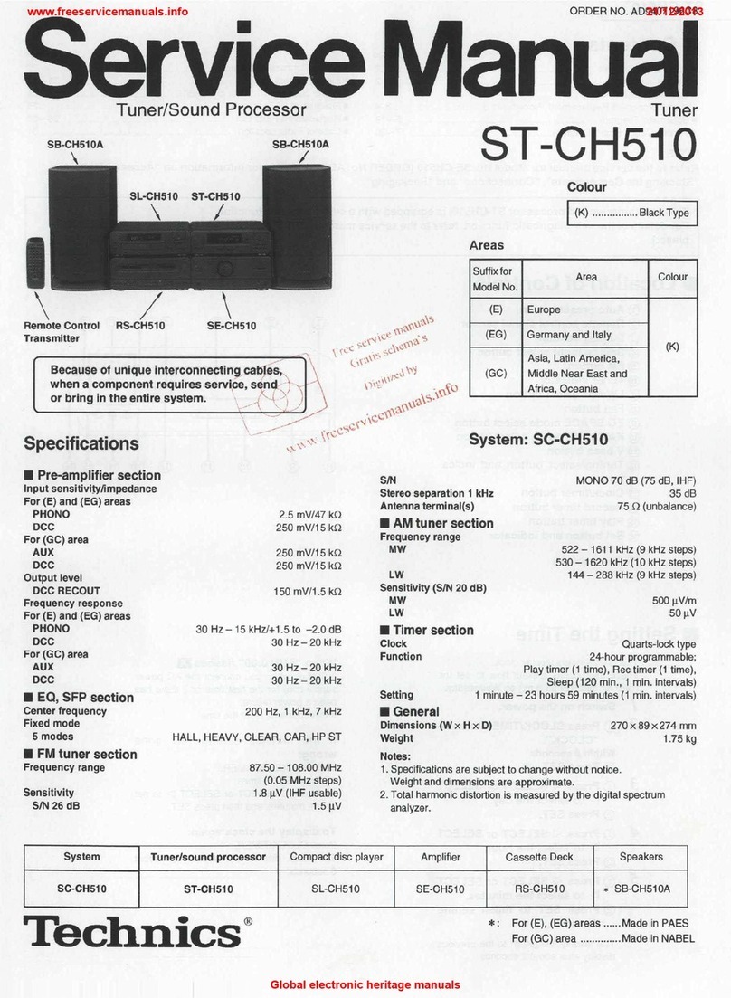
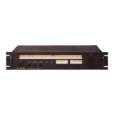
  9. Technics QUARTZ ST-X999L User manual

Technics QUARTZ ST-X999L User manual

Other Technics Tuner manuals
Technics Quartz ST-G45A User manual

Technics

Technics Quartz ST-G45A User manual

Technics ST-X302L User manual

Technics

Technics ST-X302L User manual

Technics ST-610L Building instructions

Technics

Technics ST-610L Building instructions

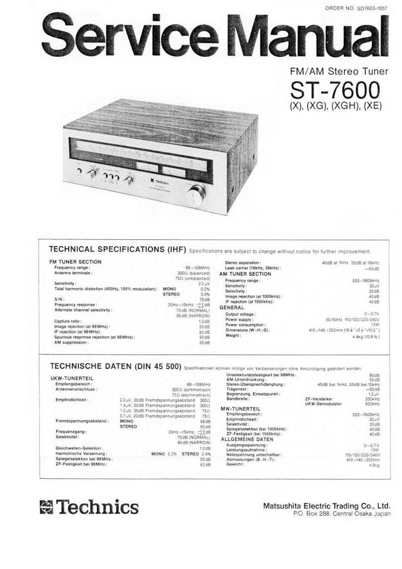
Technics ST-7300 User manual

Technics

Technics ST-7300 User manual

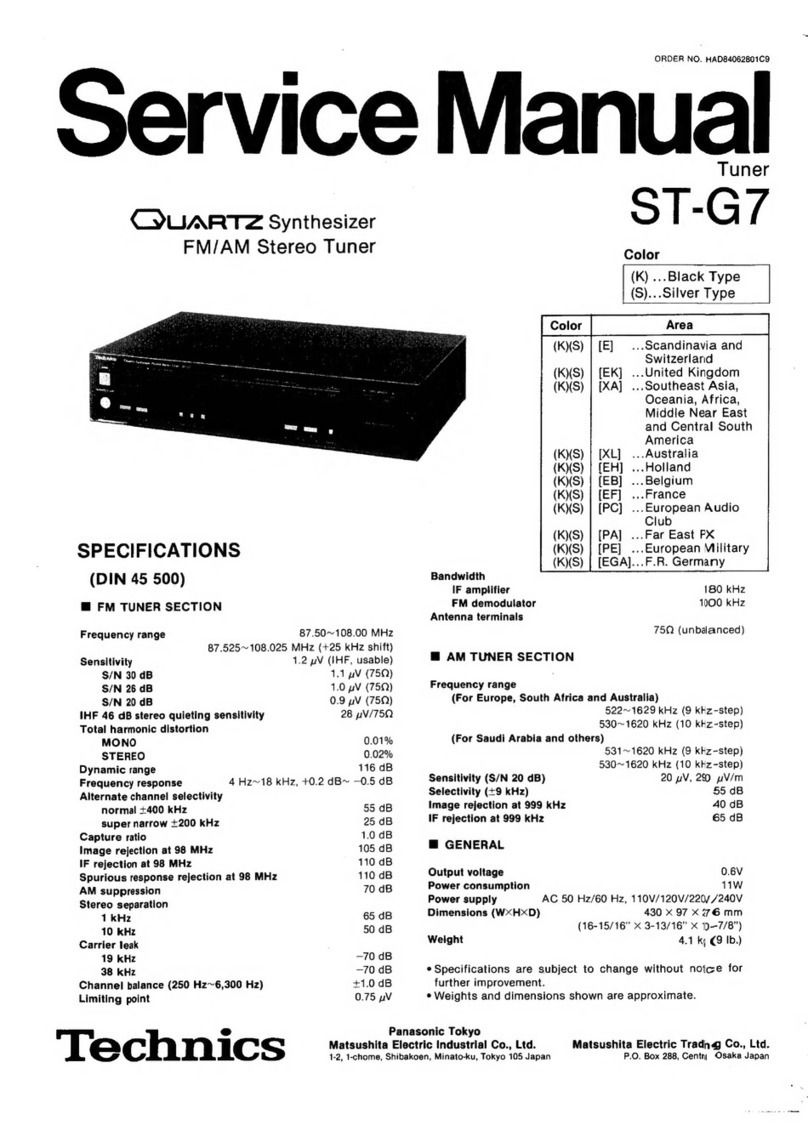
Technics Quartz ST-G7 User manual

Technics

Technics Quartz ST-G7 User manual

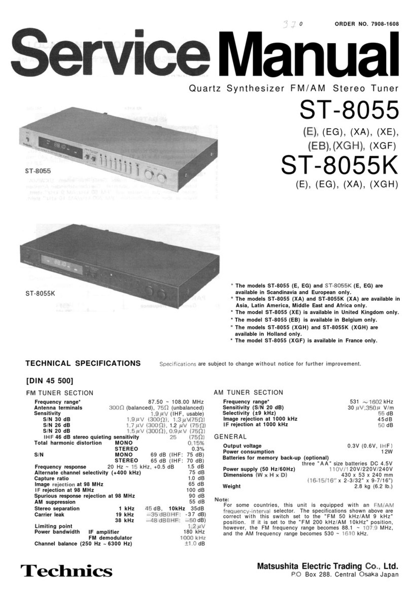
Technics ST-9030 User manual

Technics

Technics ST-9030 User manual

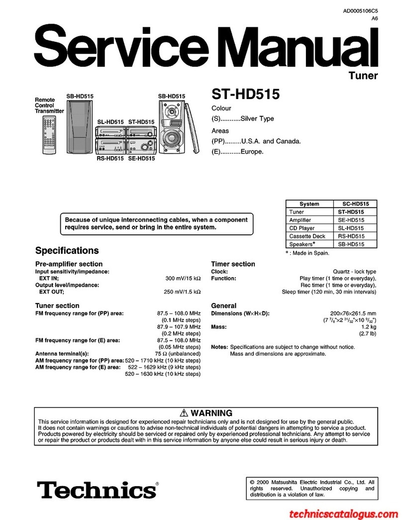
Technics ST-HD515 User manual

Technics

Technics ST-HD515 User manual

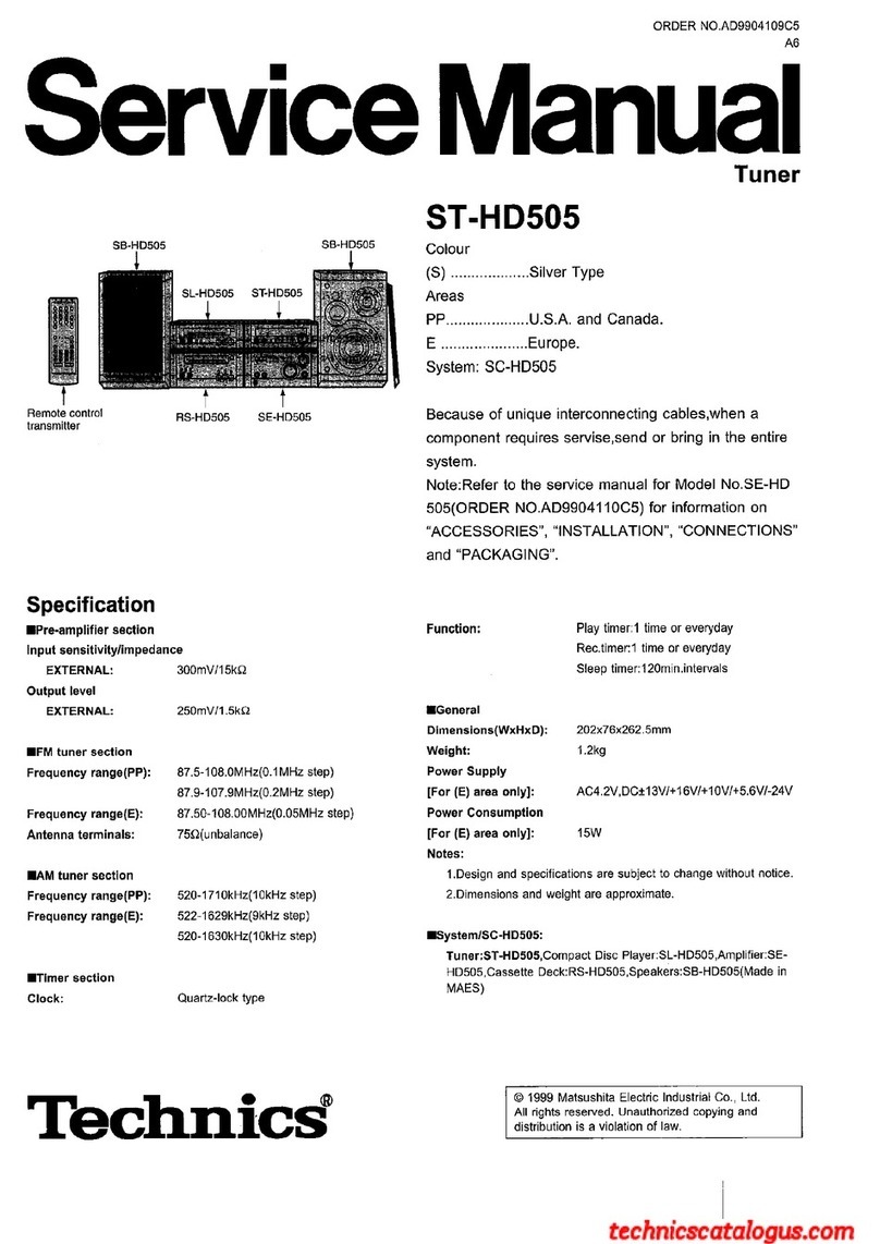
Technics ST-HD505 User manual

Technics

Technics ST-HD505 User manual

Technics ST-X302L User manual

Technics

Technics ST-X302L User manual

Technics ST-8044 User manual

Technics

Technics ST-8044 User manual

Technics Quartz ST-G7 User manual

Technics

Technics Quartz ST-G7 User manual

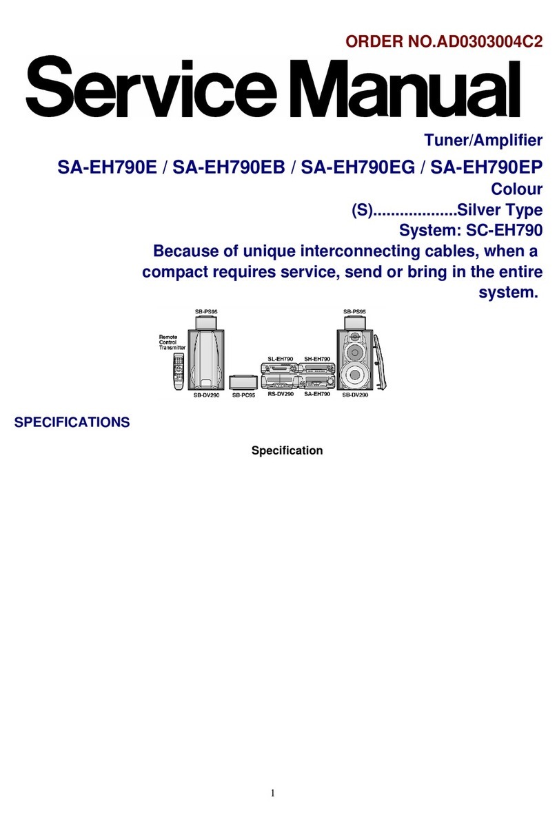
Technics SA-EH790E User manual

Technics

Technics SA-EH790E User manual

Technics ST-HD50 User manual

Technics

Technics ST-HD50 User manual

Technics ST-CH570 User manual

Technics

Technics ST-CH570 User manual

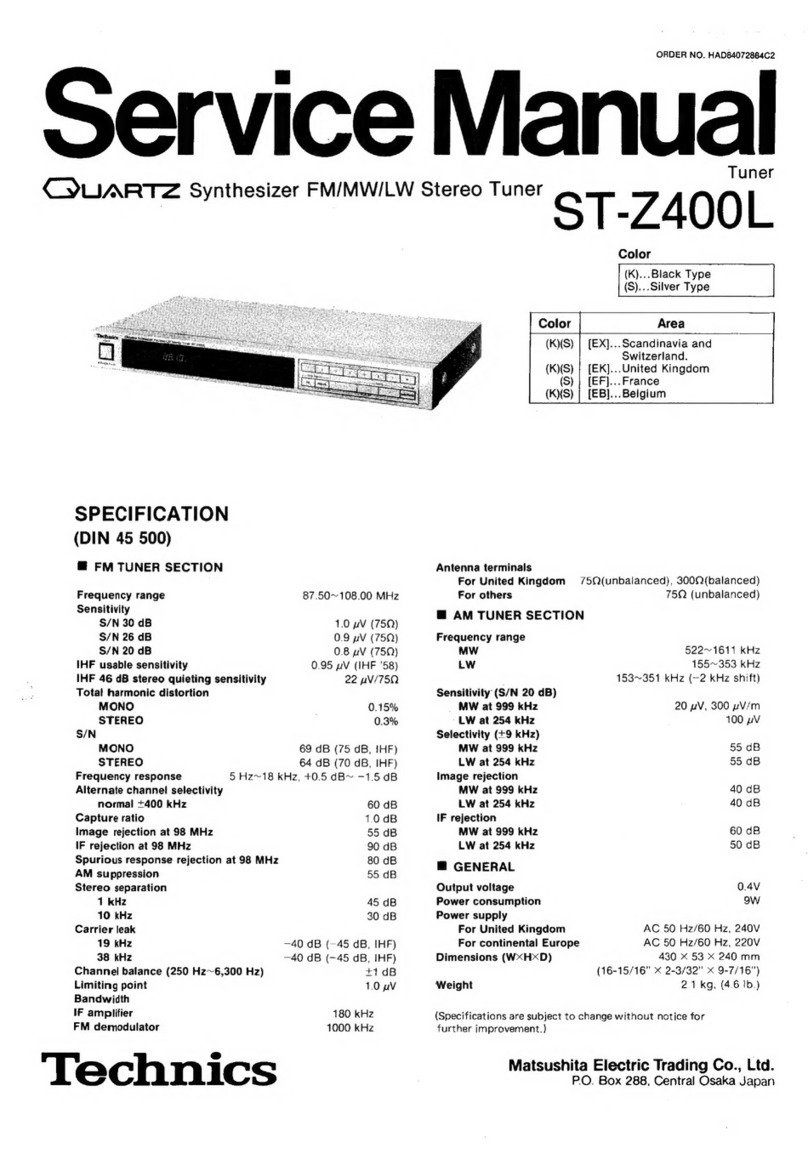
Technics QUARTZ ST-Z400L User manual

Technics

Technics QUARTZ ST-Z400L User manual
Technics ST-K50 User manual

Technics

Technics ST-K50 User manual

Technics ST-S2L User manual

Technics

Technics ST-S2L User manual

Technics ST-CH505 User manual

Technics

Technics ST-CH505 User manual

Technics ST-G90 User manual

Technics

Technics ST-G90 User manual

Technics SA-DV290EE User manual

Technics

Technics SA-DV290EE User manual

Technics ST-HD55 User manual

Technics

Technics ST-HD55 User manual

Technics QUARTZ ST-X999 User manual

Technics

Technics QUARTZ ST-X999 User manual

Technics SA-EH750 User manual

Technics

Technics SA-EH750 User manual

Technics ST-HD51 User manual

Technics

Technics ST-HD51 User manual
Popular Tuner manuals by other brands

Arcam DT91 Handbook

Arcam

Arcam DT91 Handbook

HDHomeRun 20121008 installation instructions

HDHomeRun

HDHomeRun 20121008 installation instructions

Eico HFT-92 instruction manual

Eico

Eico HFT-92 instruction manual

MFJ MFJ-928 instruction manual

MFJ

MFJ MFJ-928 instruction manual

Teac T-1D Service manual

Teac

Teac T-1D Service manual

NAD C 445 owner's manual

NAD

NAD C 445 owner's manual

Sony ST-SA5ES operating instructions

Sony

Sony ST-SA5ES operating instructions

Pioneer GEX-P700DAB Operation manual

Pioneer

Pioneer GEX-P700DAB Operation manual

Sirius Satellite Radio SC-FM1 user guide

Sirius Satellite Radio

Sirius Satellite Radio SC-FM1 user guide

Antique Automobile Radio 283501B Installation and operating instructions

Antique Automobile Radio

Antique Automobile Radio 283501B Installation and operating instructions

Sanyo FMT M15L Service manual

Sanyo

Sanyo FMT M15L Service manual

Monacor PA-1200R instruction manual

Monacor

Monacor PA-1200R instruction manual

Manhattan 176156 user manual

Manhattan

Manhattan 176156 user manual

Marantz ST-15S1 user guide

Marantz

Marantz ST-15S1 user guide

Korg HA-40 owner's manual

Korg

Korg HA-40 owner's manual

Pioneer XC-IS21T Service manual

Pioneer

Pioneer XC-IS21T Service manual

Harman Kardon TU915 Technical manual

Harman Kardon

Harman Kardon TU915 Technical manual

Tunersys WS16 1 quick start guide

Tunersys

Tunersys WS16 1 quick start guide

manuals.online logo
manuals.online logoBrands
  • About & Mission
  • Contact us
  • Privacy Policy
  • Terms and Conditions

Copyright 2025 Manuals.Online. All Rights Reserved.

ORDER
NO.
AD8903059C8
Service
Manual
Tuner
ST-X999L
Color
CYUARTZ
Synthesizer
LW/MW/FM
Stereo
Tuner
(K)...Black
Type
Area
Country
Continental
Europe
(EB)
G)
SPECIFICATIONS
(DIN
45
500)
m
FM
TUNER
SECTION
Frequency
range
87.50~
108.00
MHz
(0.05
MHz-steps)
Sensitivity
1.5
pV
(IHF,
usable)
S/N
30
dB
1.3
pV
(750
)
S/N
26
dB
1.2
pV
(
75Q
)
S/N
20
dB
0.9
pV
(750
)
IHF
46
dB
stereo
quieting
sensitivity
28
yV
/75Q
Total
harmonic
distortion
MONO
0.15%
STEREO
0.3%
S/N
MONO
70
dB
(
78
dB,IHF
)
STEREO
65
dB
(71
dB,IHF
)
Frequency
response
20
Hz
~
15
kHz,
+0.5
dB
~
-1.5
dB
Alternate
channel!
selectivity
+400
kHz
65
dB
Capture
ratio
1.0
dB
Image
rejection
at
98
MHz
46
dB
IF
rejection
at
98
MHz
70
dB
Spurious
response
rejection
at
98
MHz
70
dB
AM
suppression
55
dB
Stereo
separation
1
kHz
40
dB
10
kHz
30
dB
Carrier
leak
19
kHz
-30
dB
(-35
dB,IHF)
38
kHz
-45
dB
(-50
dB,IHF)
Channel
balance
(250
Hz
~
6,300
Hz)
+1.5dB
Limiting
point
1.2
Vv
Bandwidth
IF
amplifier
180
kHz
FM
demodulator
1000
kHz
Antenna
terminals
75Q
(unbalanced)
w@
AM
TUNER
SECTION
Frequency
range
MW
§22
kHz
~
1611
kHz
(9
kHz-steps)
530
kHz
~
1620
kHz
(10
kHz-steps)
LW
155
kHz
~
353
kHz
(9
kHz-steps)
153
kHz
~
351
kHz
(-2
kHz
shift)
"Technics
Sensitivity
(S/N
20
dB)
MW
LW
Selectivity
(+
9
kHz)
MW
(at
999
kHz)
LW
(at
254
kHz)
Image
rejection
MW
(at
999
kHz)
LW
(at
254
kHz)
IF
rejection
MW
(at
999
kHz)
LW
(at
254
kHz)
m@
TIMER
SECTION
Clock
Precision
Functions
Programmable
content
Setting
intervals
Priority
order
@
GENERAL
Output
voltage
Power
consumption
Power
supply
For
Great
Britain
For
continental
Europe
AC
50
Hz/60
Hz,110V/127V/220V/240V
Dimensions
(W
x
H
x
D)
For
others
Weight
Notes:
Third
Region
20
pV,300
pV/m
50
pV
55
dB
55
dB
40
dB
40
dB
60
dB
60
dB
Quarz-lock
type
24-hour
indication
Within
0
sec.~+
10
sec.
monthly
(at
25°C)
24-hours
programmable
weekly
(1
setting)
once
only
(1
setting)
sleep
(at
10~60
min.
10-min.
intervals)
Program
source(FM,MW,LW)
Power
ON/OFF
setting
Designation
of
preset
station
1
minute
~23
hours,59
minutes
(at
1-min.intervals)
sleep,
once,
weekly
0.3V
(0.6V,
IHF)
9W(clock
5W)
AC
50
Hz/60
Hz,240V
AC
50
Hz/60
Hz,220V
360
x
64.5
x
288
mm
(14-3/16”
x
2-17/32”
x
11-11/32”)
2.1
kg
(4.6
Ib.)
Specifications
are
subject
to
change
without
notice.
Weight
and
dimensions
are
approximate.
Matsushita
Electric
Industrial
Co.,
Ltd.
Central
P.O.
Box
288,
Osaka
530-91,
Japan
m@
CONTENTS
Page
Page
ACCESSORIES
...........
00
ccc
cee
eee
eee
ee
eeees
2
CIRCUIT
BOARDS
AND
WIRING
CONNECTION
CONNECTIONS
..........
0...
c
cece cece
eee
een
eneee
2
DIAGRAM
ii
cise
i345
cade
Wine
Relea
naan
as
14~16
LOCATION
OF
CONTROLS
............20.
ccc
eee
eeee
3
FUNCTIONS
OF
IC
TERMINALS.................005
17
DISASSEMBLY
INSTRUCTIONS
..................
4,5
DESCRIPTION
OF
FLPANEL
..................0005
18
MEASUREMENTS
AND
ADJUSTMENTS
............
6,7
RESISTORS
AND
CAPACITORS
................
19,
20
BLOCK
DIAGRAM
............
200s
cece
eee
e
ene
e
ees
8,9
REPLACEMENT
PARTS
LIST
................
20~22,
24
SCHEMATIC
DIAGRAM
...............00
0s
eee
10~13
EXPLODED
VIEW
.........
0.
ccc
cec
cece
ca
neces
23,
24
TERMINAL
GUIDE
OF
IC’S,
TRANSISTORS
AND
DIODES
©
sooner
brcha
eh
es
elses
Gere
ceeh
14
m@
ACCESSORIES
Stereo
connection
cable
(SUP2269)
...............005
1
©3-core
flat
cable
(SWKTX930E)
...............ce
ee
eae
1
@FMindoorantenna
...........
0.
ccc
ee
cece
eens
1
@Attachment
plug
(SJP9009
for
[EB]
area
only)..........
1
For
[G]
area
only
(SSA269M)
@AC
plug
adaptor
(RUP120ZBS-H
for
[G]
area
only)
......
1
For
others
areas
(SSA270M)
@AC
power
supply
Cord
...........
0.
ccc
eee
cece
eeeas
1
@AM
loop
antenna
(SPB1162T)
.............
0c
cece
eee
1
For
[EB]
area
only
(SJA193)
@AM
antenna
holders
(SMA233-1M)
...............00-
1
For
[EG]
area
only
(RJA0004)
(SMA231M)
..............000008
1
For
others
areas
(SFDACO5E03)
@Screws
(XTB3+10AFZ)
.......
0...
cece
cece
eee
eee
2
@Remote-control
transmitter
(EUR64754)
..............
1
@Batteries
(ROS)
2.0...
cece
cece
eee
eens
2
m@
CONNECTIONS
AM
LOOP
ANT
“SWITCHED”
outlet:
Audio
equipment
rated
up
to
500W
can
be
connected.
Power
is
controlled
by
power
switch
of
this
unit.
Voltage
selector
For
(G)
area
only
CONTROL
aMetiicn
OUTPUT
tro
Household
AC
outlet
+2)
This
unit
®
Stereo
connection
AC
power
supply
cord
cable
(included)
H
AC
power
supply
cord
(included)
(Included
with
amplifier)
The
configuration
of
the
AC
outlet
and
AC
power
supply
3-core
flat
cable
cord
differs
according
to
(included)
area.
Amplifier
(option)
2
00800
QOOOO®
OO
ORDER
NO.
AD8903059C8-A
CQUARTZ
Synthesizer
LW/MW/FM
Stereo
Tuner
Tuner
m
MESSUNGEN
UND
JUSTIERUNGEN
ST-X999
|.
UKW
JUSTIERUNGEN
Einstellungen
der
Bedienelemente
und
zu
verwendende
Gerate.
@
UKW-Messender(UKW-MS)
@
Stereo-Modulator
@
Verzerrungs-Analystator
@
Elektronische
Gleichstrom-Voltmeter(EVM)
@
Frequenzzahler
@
Drosselspule(100yH)
@
Widerstand(100kQ)
Anmerkung:
Fir
2202,2251,L321
und
L322
werden
bereits
justierte
Ersatzteile
geliefert.
Die
Kerne
dieser
Teile
daher
nicht
drehen.
UKW-MONO-VERZERRUNGS-JUSTIERUNG
ee
DES
UKW-MESSENDERS
Modulation
1.Der
Testaufbau
ist
in
der
Abbildung
gezeigt.
di
ucneiccaeee
2.Stellen
Sie
die
Einheit
auf
“FM(UKW)”
Betrieb.
Ausgangspegel
3.Die
Radiofrequenzanzeige
und
den
Messender
auf
100.10MHz
einstellen.
4.Den
Kern
von
T201
so
justieren,
daB
die
im
Signalzustand
gemessene
Spannung
OmV
(0+20mV)
im
300mV-Bereich
betragt.
5.7202
so
justieren,
daB
der
Verzerrungsfaktor
des
linken
Kanals
minimal
wird.
6.Schritte
4
und
5
einige
Male
wiederholen.
7.Versichern
Sie
sich,
daB
die
Verzerrungsfaktoren
von
Kanal
L
und
Kanal
R
annahernd
gleich
sind
und
auf
ein
Minimum
gehalten
sind.
Anmerkung:
Fur
die
Justierung
ist
ein
Schraubendreher
aus
Kunststoff
zu
verwenden.
MPX-SGO-JUSTIERUNG
Digitaler
Frequenzmesser
1.Der
Testaufbau
ist
in
der
Abbildung
gezeigt.
4
2.Den
UKW-Bertriebsart-Wahlshalter
in
die
“on/auto”
Po-
sition
stellen.
3.Radio
und
MeBsender
auf
100.10MHz
einstellen.
4.VR301
auf
19kHz
+
30Hz
auf
der
Frequenzzahleranzeige
justieren.
e@
VERWENDUNG
EINES
ALTERNATIVSYSTEMS
1.Stereosignal
vom
MeBsender
eingeben
oder
eine
Stereo-Sendung
empfangen.
2.VR301
justieren,
bis
die
Stereo-Anzeige
aufleuchtet.
Den
Arm
von
VR301
mit
Lack
sichern,
wie
in
der
**Stereo"’
Abbildung
gezeigt.
5
AUS
ZUSTAND
DES
UKW-MESSENDERS
Modulation
Modulationsfrequenz
Ausgangspegel,
“Stereo”
AUS
Stellung
“Stereo”
EIN
Steliung
(Anzeigebeleuchtung)
Einstetipunkt
des
pilotschaltkreis’
ST-X999L
ELNSTELLUNG
DER
PHASENSPERRUNG
EINES
SCHLEIFENVERSCHIUSSES
Digitaler
Frequenzmesser
TP901
s
UKW
ANT
(750)
[T3909
(GND)
1.Der
Testaufbau
ist
in
der
Abbildung
gezeigt.
2.Den
UKW-Bertriebsart-Wahishalter
in
die
“AM”
Position
stellen.
3.
Vornehmen
Sie
ein
Kurzschlu8
zwischen
TP903
und
TP904.
4.Stellen
Sie
den
Radiofrequenzbildschirm
auf
”1629kHz”.
5.CT901
auf
524.288kHz+
10Hz
auf
der
Frequenzzahleranzeige
justieren.
FRANCAIS
m
MEAURAGES
ET
REGLAGES
M.F.
REGLAGES
Positionnements
des
commandes
et
équipement
utilisé
@
Générateur
de
signaux
M.F.(FG-SG)
@
Compteur
de
fréquence
@
Modulateur
stéréophonique
@
Bobine
d’amortissement
d’arrét
(100uH)
@
Analyseur
de
distorsion
@
Résistance
(100KQ)
Nota:
@
Voltmétre
électronique
a
C.C.
(EVM).
eléments.
REGLAGE
DE
DISTORSION
MONOPHONIQUE
M.-F.
1.Le
raccordement
de
I’équipement
d’essai
est
montré
sur
l‘illustration.
2.Régler
l’apparei!
sur
le
mode
"FM”.
3.Ajuster
le
réglage
de
l’affichage
de
radiofréquence
et
du
générateur
de
signaux
sur
100.10MHz.
4.Régier
le
noyau
de
T201
de
telle
sorte
que
!a
tension
mesurée
sur
le
mode
de
signaux
soit
de
OmV
(OmV
+
20mV)
dans
une
plage
de
300mvV.
5.Ajuster
T202
de
tellie
que
le
facteur
de
sistorsion
du
canal
de
gauche
soit
minimisé.
6.Répéter
les
étapes
4
et
5
quelques
fois.
7.S’assurer
que
les
facteurs
de
distorsion
du
canal
de
gauche
et
du
canal‘de
droite
soient
sensiblement
les
mémes
et
au
minimum.
Nota:
Le
tournevis
de
réglage
utilisé
devra
étre
fait
en
résines.
Pour
Z202,Z251,L321
et
L322
,
ajuster
les
éléments
qui
sont
fournis.
Aussi,
ne
pas
tourner
les
noyaux
de
ces
CONDITION
DU
GENERATEUR
DE
SIGNAUX
M.F.
Moduiation
Fréquenz
de
modulation....1kHz
Niveau
de
sortie
Voitmétre
électronique
Générateur
de
signaux
M.F.
aeyo
ooeneo
OUT
ooo
oo
9
REGLAGE
MULTIPLEX
DE
L’OSCILLATEUR
COMMANDE
PAR
VARIATION
DE
TENSION
Génerateur
de
Compteur
de
fréquence
signaux
M.F.
1.Le
raccordement
de
|’équipement
d’essai
est
montré
Ae
O
sur
la
figure.
aoue
2.Régier
l’appareil
sur
la
position
“on/auto”.
3.Régiler
fe
cadran
radio
et
le
générateur
de
signaux
sur
100.10MHz.
4.Ajuster
VR301
pour
19kHz
+
30Hz
sur
Je
compteur
de
lecture
de
fréquences.
@
EN
UTILISANT
UN
SYSTEME
ALTERNATIF
1.Applique
un
signal
stéréo
a
partir
du
générateur
ou
recevoir
une
émission
stéréo.
voseari
“Stereo”
2.Ajuster
VR301
jusqu’
a
ce
que
I’indicateur
stéréo
s
HORS
CIRCUIT
HORS
CIRCUIT
éeclaire.
Collier
le
bras
de
VR301
comme
il
montré
sur
la
figure.
CONDITION
DU
GENERATEUR
DE
SIGNAUX
M.-F.
Modulation
:
7
7
Fréquenz
de
modulation...
Position
de
HORS
CIRCUIT
“Stereo”.
Niveas
de-serie
Position
de
MISE
EN
CIRCUIT
“Stereo”.
(Eciairage
de
|indicateur)
Point
de
réglage
du
circuit
pilote.
REGLAGE
DE
L’HORLOGE
EN
BOUCLE
A
BLOCAGE
DE
PHASE
Digitaler
Frequenzmesser
1.Le
raccordement
de
l’equipement
d’essai
est
montre
sur
lta
figure.
2.Régler
l’appareil
sur
ja
position
“AM”.
3.Faire
de
court-circuit
entre
TP903
et
TP904.
4.Régler
l’affichage
de
radiofréquence
sur
“1629kHz2”.
5.Ajuster
CT901
pour
524.288kHz+10Hz
sur
le
compteur
de
lecture
de
fréquences.
ESPANOL
m@
MEDICIONES
Y
AJUSTES
FM
AJUSTES
Posiciones
de
control
y
equipo
usado
@
Generador
de
sefiales
de
FM(FM-SG)
@
Frecuencimetro
@
Moduiador
estéreo
@
Bobina
de
choque(100yuH)
@
Analizador
de
distorsiones
@
Resistor(100kQ)
@
Voltimetro
electronico
de
CC(EVM)
Nota:
Para
2202,
Z251,
L321
y
L322
,
se
suministran
piezas
ajustadas.
Por
lo
tanto,
no
cambie
los
nticleos
de
estas
piezas.
AJUSTE
DE
DISTORSION
MONO
FM
1.La
conexién
del
equipo
de
pruebas
se
muestra
en
la
figura.
2.Poner
la
unidad
en
modalidad
de
”FM”.
3.Poner
la
puesta
de
la
presentacion
de
radiofrecuencia
y
generador
de
sefales
a
100,10MHz.
4.Ajustar
el
nucieo
de
T201
de
manera
que
el
voltaje
medido
en
modalidad
de
sefal
sea
OmV
(0+20mvV).
5.Ajustar
T202
de
manera
que
el
factor
de
distorsion
de
CH-I
se
minimice.
6.Repetir
los
pasos
4
y
5
algunas
veces.
7.Asegurarse
de
que
los
factores
de
distorsién
de
CH-I
y
CH-D
sean
casi
los
mismos
y
los
minimos.
Nota:
El
destornillador
de
ajuste
usado
debe
estar
hecho
de
resina.
AJUSTE
DE
MPX
VCO(OSCILADOR
CONTROLADO
POR
VOLTAJE
MPX)
1.La
conexién
del
equipo
de
pruebas
se
muestra
en
la
figura.
2.Poner
fa
unidad
en
la
posicion
de
“on/auto”.
3.Poner
la
presentaciOn
de
la
radio
y
la
puesta
del
generador
de
senales
en
100.10MHz.
4.Ajustar
VR301
para
19kHz+30Hz
en
frecuencimetro.
lectura
de
*
USANDO
SISTEMA
ALTERNATIVO
1.Aplicar
sefal
estereofonica
del
generador
o
recibir
la
emision
estereofdnica.
2.Ajustar
VR301
hasta
que
la
presentacon
de
estéro
se
encienda.
Fijar
el
brazo
de
VR301
como
se
muestra
en
la
figura.
CONDICION
DE
GENERADOR
DE
SENALES
DE
FM
Modulacién
Frecuencia
de
modulacién
Nivel
de
salida
AJUSTE
DEL
RELOJ
DEL
ENLACE
DE
LA
FASE
DE
CIERRE(PHASE-LOCKED
LOOP)
1.La
conexién
del
equipo
de
pruebas
se
muestra
en
la
figura.
2.Poner
la
unidad
en
la
posicién
de
“AM”.
3.Hacer
cortocircuito
del
TP903
y
TP904.
4.Ajuste
la
frecuencia
de
radio
a
1629kHz
en
la
pantalla.
5.Ajustar
CT901
para
524.288kH+10Hz
en
lectura
de
frecuencimetro.
CONDICION
DE
GENERADOR
DE
SENALES
DE
FM
Modulacion
Frecuencia
de
modulaci6n
Nivel
de
salida
Frecuencimetro
area
“Estéreo"
OFF
Posicién
de
“estéreo”
OFF.
Pésicién
de
“estéreo”
ON.
(indicador
encendido)
Punto
de
ajuste
de
circuito
piloto.
Digitaier
Frequenzmesser
UKW
ANT
(75Q)
Printed
in
Japan
F890300850TW/KH
m
LOCATION
OF
CONTROLS
Tuner
section
Power
“STANDBY
()/ON”
switch
(POWER
“ON/STANDBY
()”’)
Remote-control
signal
receptor
(SENSOR)
FM
mode
selector
(FM
MODE)
Tuning
buttons
(TUNING)
Band
selectors
(BAND
SELECTOR)
Preset-tuning
buttons
(1-0)
(28
CHANNEL
RANDOM
PRESET
TUNING)
Memory
button
(MEMORY)
Timer
section
Digital
frequency
display
Quartz-lock
indicator
(QUARTZ
LOCK)
Memory
indicator
(MEMO)
Channel
display
FM
stereo
indicator
(STEREO)
FM
mode
indicators
SFeaeees
Aho
oe
&
[I
ad
See
oo
41n
COU.
Fl
se
[1]
Sleep
button
(SLEEP)
[A]
Stand-by
indicator
(STANDBY)
[2]
Cancel
button
(CANCEL)
Day
display
[3]
Stand-by
button
(STANDBY)
[Cc]
Timer
ON/OFF
indicator
(ON/OFF)
[4]
Read
button
(READ)
[D]
Time
display
[5]
Set
button
(SET)
[E]
Colon
indicator
[6]
Select
buttons
(SELECT)
[F]
Timer-mode
indicator
(ONCE/WEEKLY/SLEEP)
Clock
set
button
(CLOCK
SET)
*
The
operating
procedures
and
features
are
similar
to
those
for
and
of
the
ST-X990L.
ST-X999L
m@
DISASSEMBLY
INSTRUCTIONS
@®
and
remove
the
holder
in
the
direction
of
the
arrow
@).
ieee
Removal
of
the
main
P.C.B.
Procedure
|
1.
Remove
the
10
screws
(Q~@).
133
ee
No.
|
Removal
of
the
cabinet
Procedure
|
eRemove
the
4
screws
(Q~O).
1
o,
ae
Removal
of
the
front
panel
Procedure
|
1,
Remove
the
flat
cable
(J901,
J902).
152
2.
Push
the
front
panel
in
the
direction
of
the
arrow
3.
Remove
the
3
secrews
(@~@).
4.
Remove
the
front
panel
in
the
direction
of
the
arrow.
Removal
of
the
flat
cable
Pull
out
the
flat
cable
while
pressing
the
Flat
connector
cable
/
Connector
2.
Remove
the
3
screws
(@~®).
3.
Slightly
puil
the
front
panel
toward
you
and
remove
the
main
P.C.B.
ST-X999L
Ref.No.
|
Removal
of
the
preset
tuning
SW
P.C.B.
4
and
band/tuning/timer
operation
SW
P.C.B.
Procedure
|
1.
Remove
the
4
screws
(@~@).
Spection
SW
PCB.
1-2-4
|
2.
Remove
the
band/tuning/timer
operation
SW
Al
P.C.B.
3.
Remove
the
1
screw
(@).
4.
Push
the
4
claws
and
remove
the
preset
tuning
SW
P.C.B.
1.
Remove
the
battery
cover
lid.
3.Insert
a
screwdriver
blade
between
the
2.
Remove
the
one
screw
(Q).
upper
and
lower
covers
inside
the
battery
:
compartment
and
them
slowly
loosen
the
bottom
cover.
Battery
cover
lid
ST-X999L
m™
MEASUREMENTS
AND
ADJUSTMENTS
FM
ADJUSTMENT
Control
positions
and
equipment
used
@
FM
signa!
generator(FM-SG)
@
Frequency
counter
@
Stereo
modulator
@
Choke
coil(100yuH)
@
Distortion
analyser
@
Resistor(100kQ)
@
DC
electronic
voltmeter(EVM)
Note:
For
Z202(AM-IFT),
Z251(AM
ANT
and
OSC
coil),
L321
(L.P.F)
and
L
322(L.P.F),
they
are
supplied
as
adjusted
parts.
So,
do
not
turn
the
cores
of
the
parts.
FM
MONO
DISTORTION
ADJUSTMENT
FM
SIGNAL
GENERATOR
CONDITION
1.Test
equipment
connection
is
shown
in
figure.
Modulation
2.Set
the
unit
to
“FM”
mode.
Modulation
frequency
3.Set
the
radio
frequency
display
and
signal
generator
to
Output
level
100.10MHz.
4.Adjust
the
core
of
T201
so
that
the
voltage
measured
in
signal
moae
is
OmV(0+20mV)
in
300mV
range.
5.Adjust
T202
so
that
the
distortion
factor
of
L-CH
is
mini-
mized.
6.Repeat
steps
4
and
5.
7.Make
sure
that
the
distortion
factors
of
L-CH
and
R-CH
are
nearly
the
same
and
minimum.
Note:
The
adjusting
screwdriver
used
should
be
made
of
resin.
MPX
VCO
ADJUSTMENT
1.Test
equipment
connection
is
shown
in
figure.
2.Set
the
unit
to
“on/auto”
position.
3.Set
the
radio
frequency
display
and
signal
genarator
to
Atay
oO
100.10MHz.
4.Adjust
VR301
for
19kKHz+30Hz
on
frequency
counter
reading.
USING
ALTERNATE
SYSTEM
1.Receive
the
stereo
broadcast.
2.Adjust
VR301
until
stereo
indicator
lights
up.
Fix
the
arm
of
VR301
as
shown
in
figure.
Frequency
counter
FM
SIGNAL
GENERATOR
CONDITION
Modulation
Modulation
frequency
.
Output
level
“Stereo”
OFF
position
“Stereo”
ON
position
(Indicator
lighting)
Adjust
point
of
pilot
circuit