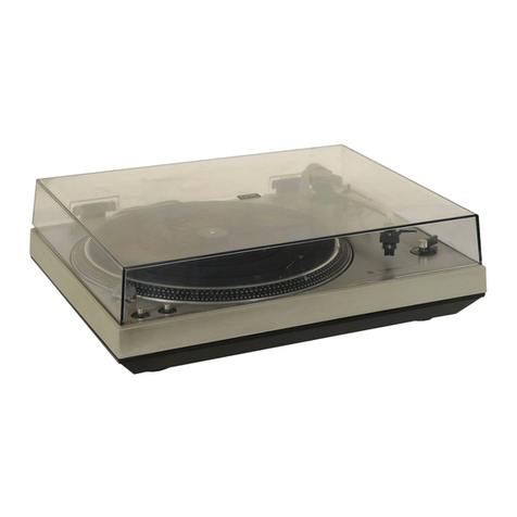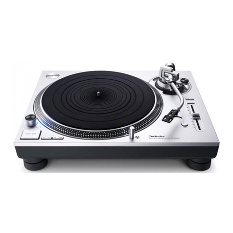
Wewantlothankyou(or
selecting
the
SP-25.
For
optimumperformance,werecommendthat
you
readtheseinstructionscarefully.
Beforeuse
Caution:
•Never
connect
theACpower
plug
before
assembly
has
beencompleted
•Attachthedustcoverlast,sothatassemblyand
adjustments
canbemade
most
conveniently.
•Checklistofparts
Turntableunit1
Turntableplaner4 1
Turntablemal1
4$-rpmadaptor1
Main
unit
fixing
screw
4
Ground
wire(GND) 1
Installationdiagram1
•Installationofthegroundwire(GND)tothe
GNDterminal.
(See
Fig.
2.)
•Buildingyourownbaseorcabinetforthis
model
witha targestartingtorqueof1,5legem(lo-in)has
thesuperiorfeatureofreachingconstantspeedin0.7
second
(at33-1/3rpm.).
For
thisreasonwerecommendthatyouusedurableand
heavy
material
The
thickness
ofthebase
should
bemoreman3
cm
(i
-11
/
64inch).
Aiso
use
durableandstablemuiators(lega).
Werecommendthatyoupurchasetheoptionalturntable
base
Technics
SH-15B2.
designedexclusivelyfortheSP-
25.
(See
Fig.
3.)
•Drillandcutoutthebaseaccordingtothe
Installationdiagram
The
installationdiagram
is
drawnini/iactual
size
As
paperhasa tendencytostretchwesuggestthatyou
check
thediagrambefore
using
itasa tempiale.
Check
the
tonearmmountingpositionforproperalignment(followthe
lonearmmanufacturer's
specifications)•
Also
makesuretoallowsufficientclearanceforpower
connector
andoutputterminalsofthetonearm*
Caution
forsafeuseofthis
apparatus[FORUKONLY]
Caution
e
This
apparatus
isdouble
insulated,
safely
earthnotrequired.
Important
eThe
wiresinthlamainaleadarecolouredInaccordance
withthefollowingcode:
Blue;
Neutral
Brown:
Live
As
the
colours
ofthewiresinthe
mams
lead
ofthisapparatus
maynotcorrespondwiththecolouredmarkingsidentifying
theterminalsInyourplug,proceedasfollows.
The
wirewhichIscoloured
BLUE
mustbeconnectedtothe
terminal
which
is
markedwith
the
letterNor
coloured
BLACK.
The
wire
which
is
colouredBROWN
must
be
connected
tothe
terminalwhichismarkedwiththeletterL
or
coloured
RED
This
equipmentshouldbedisconnectedfromthemains
whennotinuse.
Assembly
andset-up
Caution;
Takecarenottodamagethepower
supply
cordandbushingwhensettingupor
installingtheturntableintoasupporting
enclosure.
Assembling
is explainedbasedontheoptionalTochmcs
turntaWeba
se
SH-15B2
for
reference
meases
wheretheunitis
installed
inanothercabinet,
SH*15B2
isprovidedwith
screw
holes(4
places)
formounting
SP-25.
1
Install
SP-25,
withthe
screw
holes
-n.gnec(See
Fig.
4.)
2.
Secureh/
holdat4
places
bythe
screws
suppliedwithSH-
1582.(See
Fig.
5.)
3.
Pull
outthepowercordandground
wire
(GND)fromunoe'
theturntable
base.
4Aftertheabove,installtheturntableplatterandturntable
mat.
Connections
•ACline-voltageselector<see
Fig.
e.)
Caution:
Makesurethattheturntable'sACime-voitageselectoris
matchedtoyourlocalvoltagebeforeconnectingtheAC
powerplug,Never
connect
to
a
DCsocket.
Ifthepre-seiectedvoltage*sdifferentfromyourlocal
voltageturnthe
AC
fine-voltage
selector
witha screwdriver
so
thatit
corresponds
toyour
locar
voltage,
(See
Fig.
6)
The
ACime*vottageselectorislocatedundertheturntable
platter.
•ConnecttheACpowerplug.
Connect
the
AC
power
pJug
toanAC
waH
socket.
•Connecttheoutputterminals.
Note:
e&esuretoconnectthegroundterminalfirmlytothe
amplifierorreceiver.
Jf
thisconnectionis notmadeoris
loose,
a power
source
"HUM**willresult.
Placement
•Placetheunit
In
a
stableandhorizontalposition,where
therela
little
ornovibration.
•Locatetheunitasfarawayfromthespeakersaa
possible
andIsolatetheunitfromsoundradiationfrom
them.
•DonotplacetheunitwhereItlaexposedtodirectsun.
dust,
molatureorheat.
•KeepItIna wellventilatedplace.
•Whena radiolaplacedtoo
close
totheturntableandIs
playedwhiletheturntableIsInoperation,interference
toAM/FMreceptionmayresult.
