Technimount System Safety Arm System 500 User manual

SAFETY ARM SYSTEMTM
USER GUIDE

2 SAS UG 201912-R01 www.technimount.com
Return To Table of Contents
Copyright Technimount System, Subsidiary of Technologies CGC Inc. 2019. All Rights Reserved. No part of this
Safety Arm System is a Trademark of Technimount System.
The Safety Arm System is patented, under reference # 62/909-408
Stryker® stretcher models and numbers are registered trademarks of Stryker.
Technimount Products.
comments to our Customer Service Department at customerservice@technimount.com.
www.technimount.com SAS UG 201912-R01 3
Return To Table of Contents
CORPORATE HEADQUARTERS
Customer Service or Technical Support
3770 Jean Marchand Street, Suite 100
Quebec (QC) G2C 1Y6
Canada
www.technimount.com
T + 1 581.998.9820
F + 1 855.339.6351
customerser[email protected]
techsupport@technimount.com
NOTE:
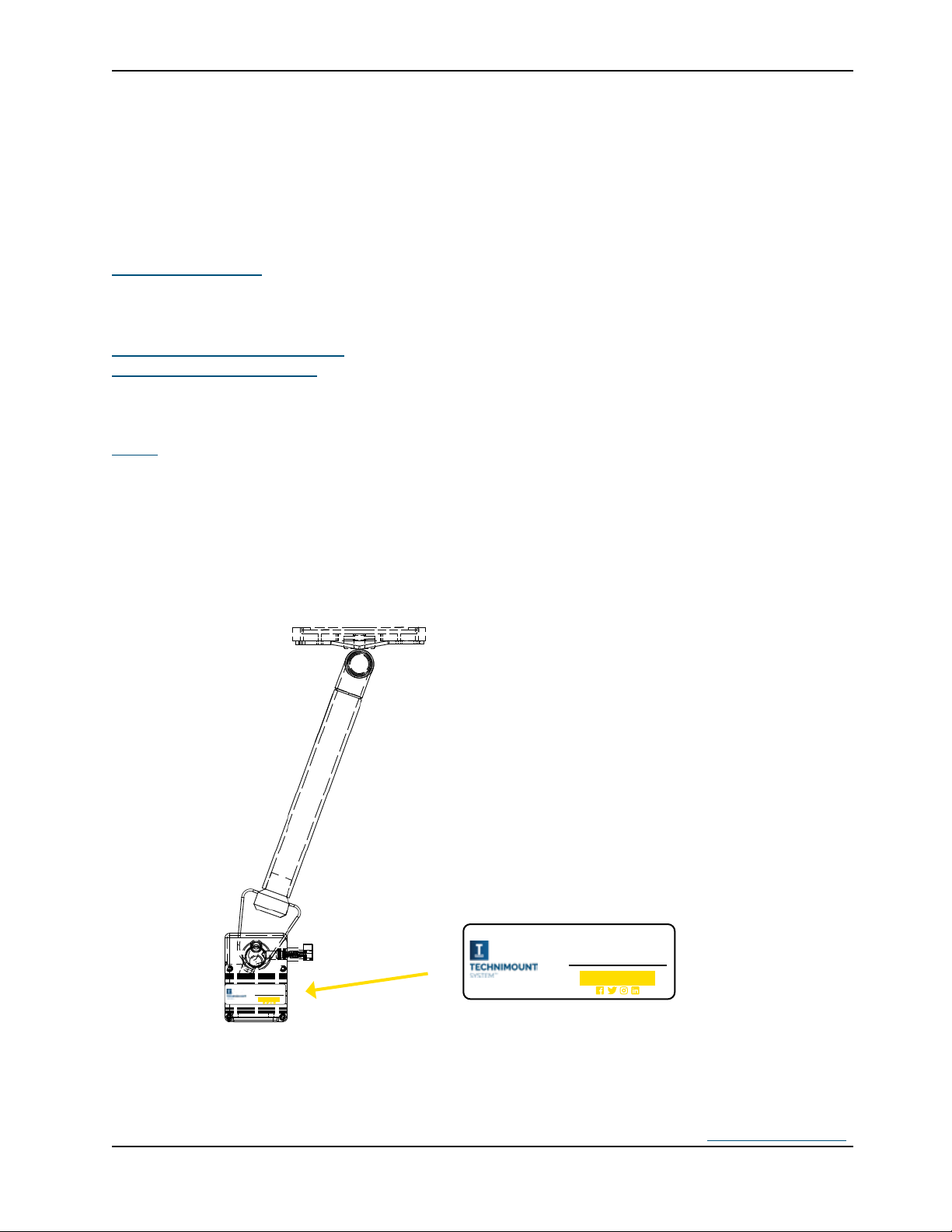
SERIAL NUMBER LOCATION
Made in Canada
S/N:
Made in Canada
S/N:

4 SAS UG 201912-R01 www.technimount.com
COPYRIGHT ............................................................................................................................................................2
CONTACT INFORMATION.......................................................................................................................................3
INTRODUCTION .....................................................................................................................................................6
Product Description .....................................................................................................................................................6
Intended use of the Product .......................................................................................................................................6
Symbols and Definitions ...............................................................................................................................................7
Warning / Caution / Note .............................................................................................................................................8
Identification of Components ......................................................................................................................................9
Lock Pin ...................................................................................................................................................................9
Safety Pin ................................................................................................................................................................9
Clamp Block ..........................................................................................................................................................10
Saefty Arm ............................................................................................................................................................10
Hardware Kit for the Safety Arm .......................................................................................................................11
Product Options Available .........................................................................................................................................11
Installation Related to the Stryker Powerload Stretcher ......................................................................................11
Specifications ...............................................................................................................................................................12
PRODUCT INFORMATION.................................................................................................................................... 15
Product Illustration with Other Equipment on Stretcher ....................................................................................15
Installation Overview ..........................................................................................................................................16
SUMMARY OF SAFETY PRECAUTIONS ................................................................................................................ 17
Warning/Caution/Note ..............................................................................................................................................17
INSTALLATION GUIDE .......................................................................................................................................... 20
Removing Packaging for Installation .......................................................................................................................20
Tools Required for Installation.................................................................................................................................20
Cot/Stretcher Orientation Diagram ..........................................................................................................................21
Preparing the Cot/Stretcher for Installation ..........................................................................................................22
Removing the IV Pole or Changing the Side of the IV Pole ..............................................................................22
Safety Arm System Installation ..................................................................................................................................25
Position on the Cot/Stretcher ............................................................................................................................25
Patient Right and Left Installation .................................................................................................................................25
Position on the Cot/Stretcher (Continued) .......................................................................................................26
Patient Right Installation ................................................................................................................................................26
Installing the Clamp Block (Patient Right) .......................................................................................................27
Installing the Standard Surface Base onto the Safety Arm System Upper Plate ............................................32
OPERATION CAUTION AND WARNING ............................................................................................................... 34
OPERATION GUIDE .............................................................................................................................................. 35
General Operating Guidelines ....................................................................................................................................35
Recommended Lifting Techniques .......................................................................................................................35
Recommended Handling Positions .....................................................................................................................36
Operating the Safety Arm System ..............................................................................................................................37
Lowering the Safety Arm.....................................................................................................................................38
Raising The safety Arm.........................................................................................................................................39
Removing the Safety Arm ....................................................................................................................................40
SAFETY ARM SYSTEM OPTIONS .......................................................................................................................... 42
Stryker PowerPro options .........................................................................................................................................42
Stryker MX-PRO Options .............................................................................................................................................42

www.technimount.com SAS UG 201912-R01 5
MAINTENANCE GUIDE......................................................................................................................................... 43
Cleaning the Safety Arm System ................................................................................................................................43
Cleaning Process ..................................................................................................................................................43
Cleaning Solutions...............................................................................................................................................43
Removal of Iodine Compounds ...........................................................................................................................44
Preventive Maintenance .............................................................................................................................................44
Lubrication ...........................................................................................................................................................44
Inspection Process and Schedule...............................................................................................................................45
Preventive Maintenance Program ......................................................................................................................45
inspection and Maintenance Record .........................................................................................................................46
Training Record ...........................................................................................................................................................47
Replacement Parts .......................................................................................................................................................48
WARRANTY .......................................................................................................................................................... 49
Warranty Policy ..........................................................................................................................................................49
Warranty Options .......................................................................................................................................................50
three warranty options for Technimount Products ........................................................................................50
International Warranty Clause .................................................................................................................................50
RETURN POLICY ................................................................................................................................................... 51
Return of Merchandise ..............................................................................................................................................51
Prior to 30 Days ...................................................................................................................................................51
Prior to 45 Days ...................................................................................................................................................51
Prior to 60 Days ...................................................................................................................................................51
Return Merchandise Authorization ...................................................................................................................51
Damaged Merchandise ........................................................................................................................................51

6 SAS UG 201912-R01 www.technimount.com
Return To Table of Contents
PRODUCT DESCRIPTION
on a top-down movable arm, installed with a clamp block on the stretcher frame. It is designed to support and
transport portable medical devices with a maximum weight of 45 lbs. in pre-hospital and hospital environments. The
medical device can be removed and stored safely when not in use. When the arm is used in emergency vehicles with
stretcher. In case of emergencies, the side locking pin can be removed in less than 5 seconds, by releasing or pulling
INTENDED USE OF THE PRODUCT
(Stryker Stretchers MX-Pro and PowerPro models). The mount is intended to support and transport medical equipment
and adults).
movement or transport of the stretcher.
developed to be used on an ambulance stretcher and intended for front-line responders who have received the
more, depending upon use.
The Safety Arm Systems are intended for transport purposes only. They are not intended for more than one unit nor

8 SAS UG 201912-R01 www.technimount.com
Return To Table of Contents
WARNING / CAUTION / NOTE
or damage to the equipment or other property. This includes special
damage that may occur as a result of use or misuse.
NOTE
www.technimount.com SAS UG 201912-R01 9
Return To Table of Contents
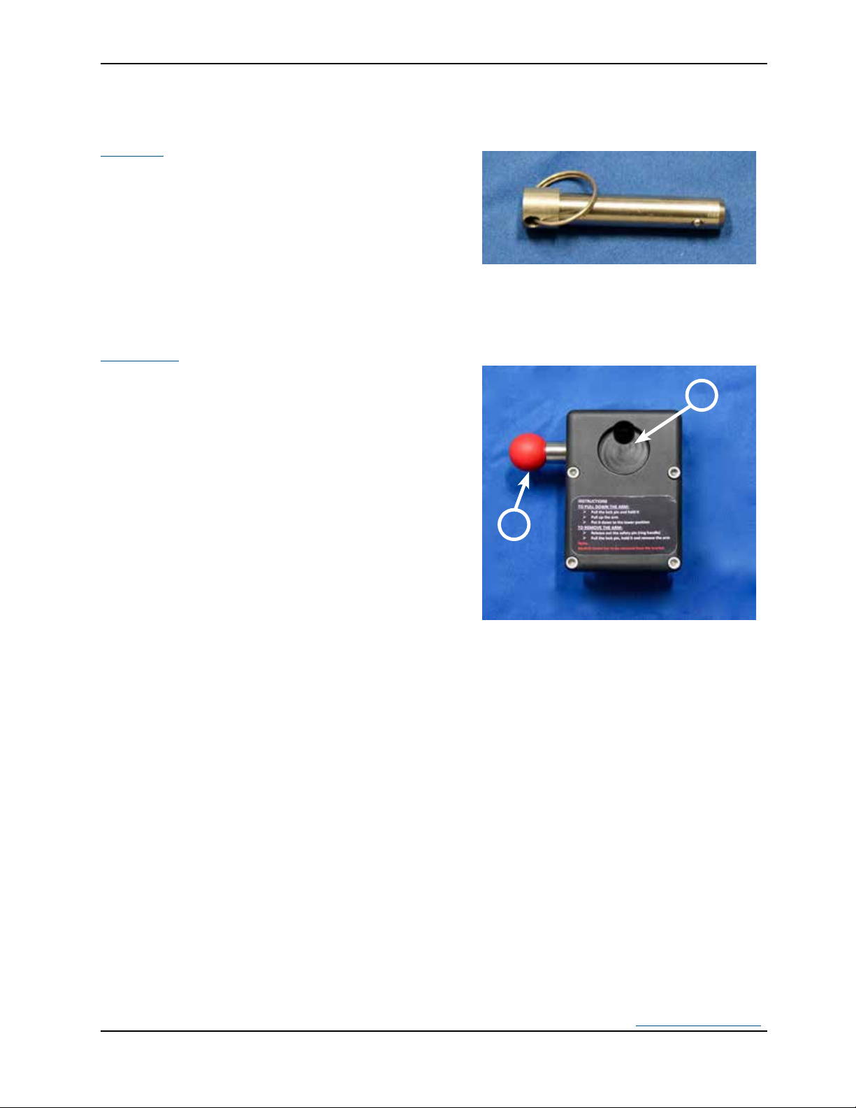
IDENTIFICATION OF COMPONENTS
ring. It is used to lock the Safety Arm System inside
the clamp block. It goes through the clamp block and
clamp block.
handle mechanism used for locking the arm in the
a) Side Lock Pin Insert
b) Safety Pin with red handle
LOCK PIN WITH FINGER RING
CLAMP BLOCK WITH SAFETY PIN
INSERTED

10 SAS UG 201912-R01 www.technimount.com
Return To Table of Contents
IDENTIFICATION OF COMPONENTS
(CONTINUED)
The clamp block is the two (2) part metal system
screws; as shown in picture 3 and 4.
CLAMP BLOCK BEFORE ASSEMBLY
PICTURE 4: CLAMP BLOCK AFTER
ASSEMBLY
OF THE BASE TO THE PLATE
YELLOW SAFETY ARM
The base mount (upper plate) is welded onto the
safety arm as shown in picture 5. The yellow safety
arm goes into the clamp block as shown in picture 4.

www.technimount.com SAS UG 201912-R01 11
Return To Table of Contents
of the standard surface base on the upper plate.
1. 2 screws 10-32 x 1-3/4” Philips (star)
2. 2 screws 10-32 x 1-1/4” Philips (star)
3. 4 hexagonal nuts 10-32 x 3/8”
4. 2 hexagonal SS Caps 10-32
PRODUCT OPTIONS AVAILABLE
1. The locking pin is available in red. Coloring of the stainless steel pin is achieved through a chemical process called
or chip. Much harder surface than paint and powders.
2. The yellow color is the standard color for the Safety Arm System. Black is also available.
3. To install the IV Pole on the same side of the Safety Arm Stretcher, an IV Pro Adapter plate is required to support
cust[email protected]
INSTALLATION RELATED TO THE STRYKER POWERLOAD STRETCHER
9The spacer block is the shim installed under the “V” bracket on the cot/stretcher frame when a power load system
is installed with the cot/stretcher. This bracket is NOT a Technimount part.

12 SAS UG 201912-R01 www.technimount.com
Return To Table of Contents
SPECIFICATIONS
Cot/Stretcher Brand and Model Available Stryker Cot/Stretcher
45 lbs
Model Safety Arm System - 500
ProXT, PowerPro, model 6085-6086, 6500 and 6506
Part Number (Depending on Cot Model) 500-00-XXXX
Upper and lower
Material Manufacturing High-density aluminium
Clamp box on side frame
Dimensions (Inches)
▪
▪Overall Length - With Clamp Block
▪Cot/Stretcher (Frame) to Under Base Plate
▪Cot/Stretcher (Frame) to Under Base Plate
Weight
▪ 3.8 lbs
▪Clamp Block 2.15 lbs
▪ 6.8 lbs
Colors Available - Black
- Yellow
Angle of the Base Plate with the Arm 70°
Note: Safe Working Load
Safe Working Load indicates the sum of
the medical device and accessory weight
www.technimount.com SAS UG 201912-R01 13
Return To Table of Contents
SPECIFICATIONS CONTINUED
4 holes
Lower
Recommended Number of Operators 2
Bracket Pro Standard and extended base
Clamp Block
~5 minutes
Less than 5 seconds
SAE J3043
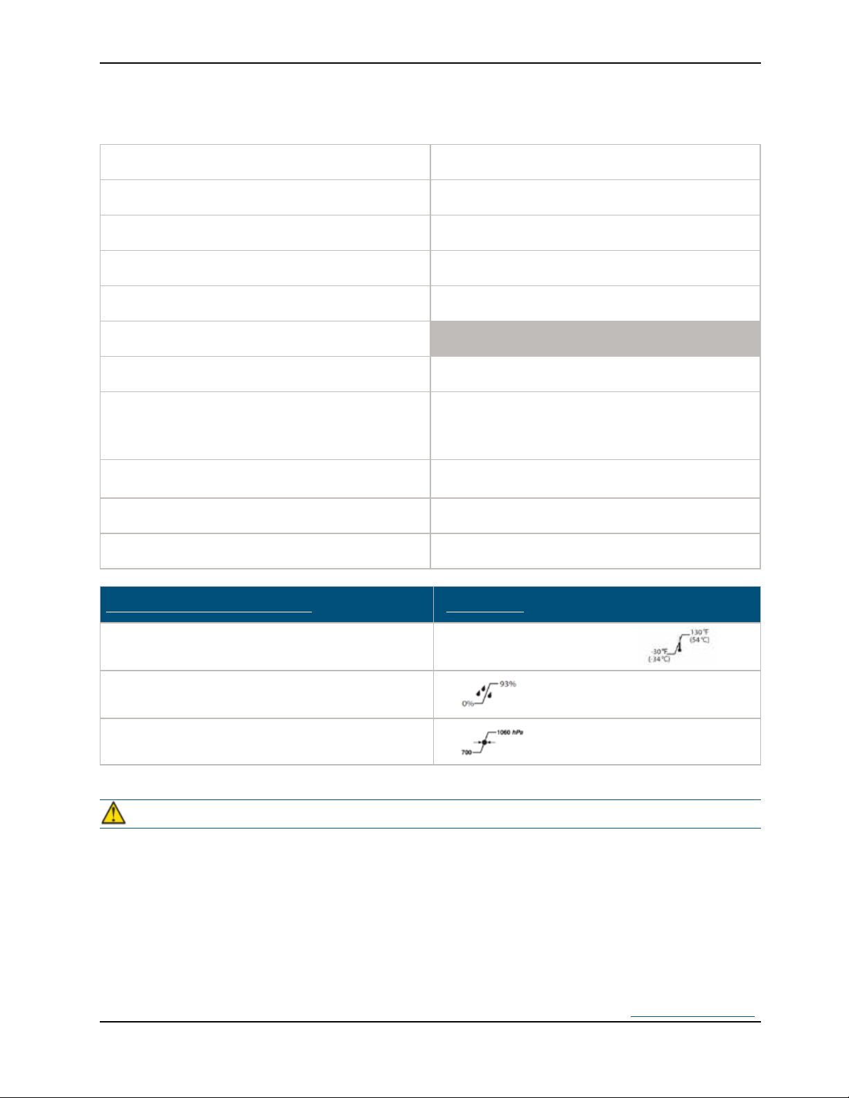
ENVIRONMENTAL CONDITIONS OPERATION
Temperature -30 °F (-34 ° C) to 130 °F (54 °C)
Atmospheric Pressure
CAUTION
9
9

14 SAS UG 201912-R01 www.technimount.com
Return To Table of Contents
NOTE
and SAE J3043. Patents on product currently pending.
3770 Jean Marchand Street, Suite 100
Quebec (QC) G2C 1Y6
Canada
www.technimount.com
T + 1 581.998.9820
F + 1 855.339.6351
www.technimount.com SAS UG 201912-R01 15
Return To Table of Contents
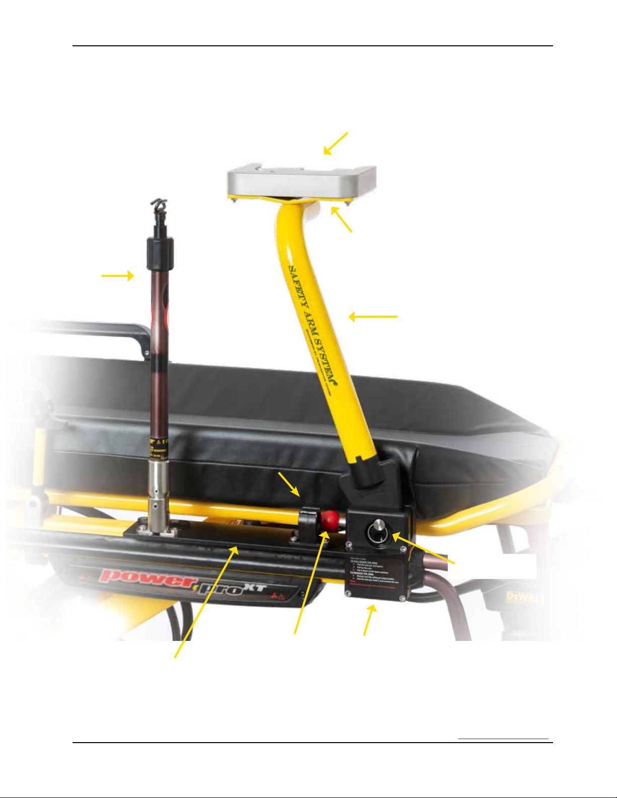
PRODUCT ILLUSTRATION WITH OTHER EQUIPMENT ON STRETCHER
Standard Surface Base Mount
to Install Medical Devices with
IV Pole
Side Lock Pin
(Finger Ring)
Fixed
Clamp Block
Movable Arm
Fixed
Safety Pin
(Red Round
Handle)
Arm Surface
Plate to Install
the Standard
Surface Base
IV Pro Adapter
with IV Pole
and IV Pole
Holder Installed
IV Pole
Holder


www.technimount.com SAS UG 201912-R01 17
Return To Table of Contents
WARNING/CAUTION/NOTE
WARNING
9Always hold the arm when you manipulate it.
9 (locked)
(un-locked). Failure to do so can cause damage to the equipment.
9To avoid injury, hands should be clear of the black clamp block and arm pivot while loading and unloading the
9
as described in this user guide.
9
9It is the responsibility of the operator of the cot/stretcher to ensure that the Safety Arm System being used with
used with Technimount System products.
9
9
may damage the product. Always secure the arm with the safety pin. Install and use the safety pin as described in
this user guide.
9To avoid any injury, verify that the side safety pin has been pulled all the way through the clamp block before
9
or operator and/or damage to the arm may occur.
9
product is fully understood. Improper use may cause injury to the operator.
9
Failure to do so, can cause damage to the product and/or the cot/stretcher.
9
9
operator.
9
lowering the arm.
9
9
door, or pull the cot/stretcher with the arm.
9

18 SAS UG 201912-R01 www.technimount.com
Return To Table of Contents
WARNING/CAUTION”NOTE (CONTINUED)
9
9
device bracket for medical devices.
9
9
9
9If you want to remove the arm from the system, make sure you remove the medical device from the surface base
9Improper maintenance can cause injury or damage to the product. Maintain the Safety Arm System as described in
this user guide. Use only Technimount approved parts and maintenance procedures. Using unapproved parts and
9Failure to properly clean or dispose of corrosive products will increase the risk of premature damage and may
9
more operators.
9
SIDE VIEW OF THE CLAMP BLOCK
AND ARM PIVOT
SIDE VIEW OF THE CLAMP
BLOCK AND ARM PIVOT

www.technimount.com SAS UG 201912-R01 19
Return To Table of Contents
WARNING/CAUTION”NOTE (CONTINUED)
CAUTION
9
9Inspect regularly the clamp block and surface base for any issue and loose screws, bolts and nuts.
NOTE
9Some cleaning products are corrosive in nature and may cause damage to the product if used improperly. If
such products are used to clean Technimount equipment, the equipment must be rinsed with clean water and
thoroughly dried following the cleaning. Failure to properly rinse and dry the Arm will leave a corrosive residue on
9
Safety Arm is to be located. The Safety Arm System cannot be reversed as the clamp block has been designed for
9
9
the product.
9This user guide should be considered a permanent part of the Safety Arm System and should remain with the
product even if the arm is subsequently sold.
9
Support at +1.581.998.9820.

20 SAS UG 201912-R01 www.technimount.com
Return To Table of Contents
REMOVING PACKAGING FOR INSTALLATION
1. Unpack boxes and check all items for proper operation.
2. Ensure that all shipping and packaging materials have been properly removed from the product(s) prior to
installation.
3. Identify all of the product components and hardware prior to starting the installation.
4. Some hardware or parts provided might not be applicable to the model of your cot/stretcher.
5. The Safety Arm System must work properly before it is put into service.
6. Refer to the identication of components at the beginning of this user guide if needed.
NOTE
9
TOOLS REQUIRED FOR INSTALLATION
techsuppor[email protected]
NOTE
9
damage to the threads.
9
ALLEN KEY 3/16 IN
SCREWDRIVER
RUBBER HAMMER
Table of contents


