Tinker & Rasor APS Instruction sheet


Table of contents
Other Tinker & Rasor Security Sensor manuals
Tinker & Rasor
Tinker & Rasor M1/AC Instruction sheet
Tinker & Rasor
Tinker & Rasor M/2 Instruction sheet
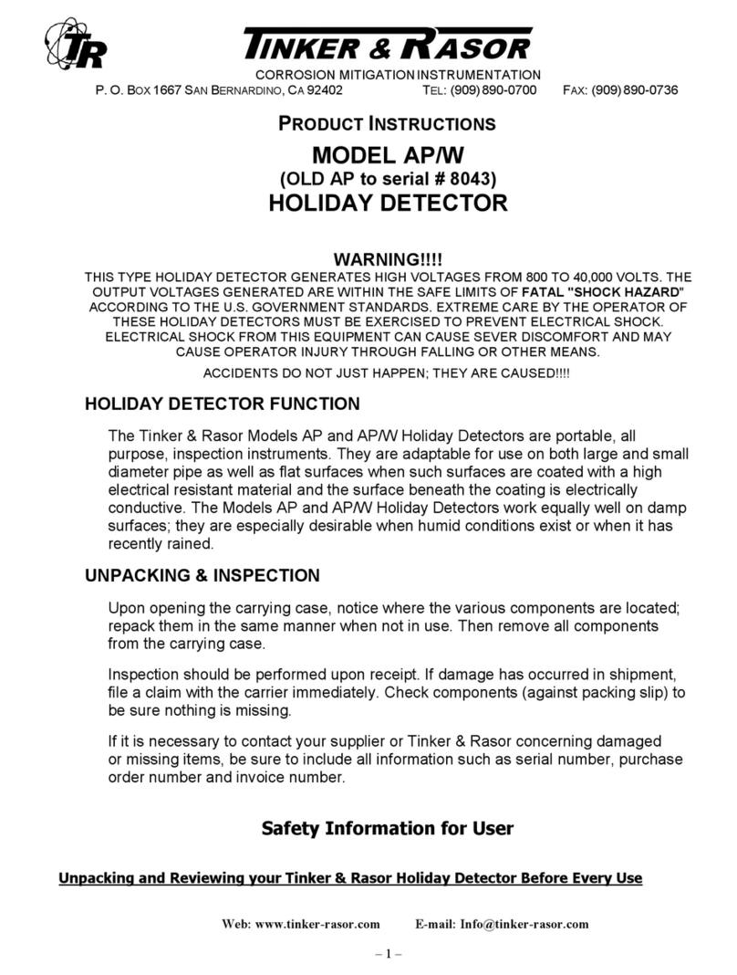
Tinker & Rasor
Tinker & Rasor AP/W User manual
Tinker & Rasor
Tinker & Rasor APS User manual
Tinker & Rasor
Tinker & Rasor AP/AC Instruction sheet

Tinker & Rasor
Tinker & Rasor 7-T Instruction sheet
Tinker & Rasor
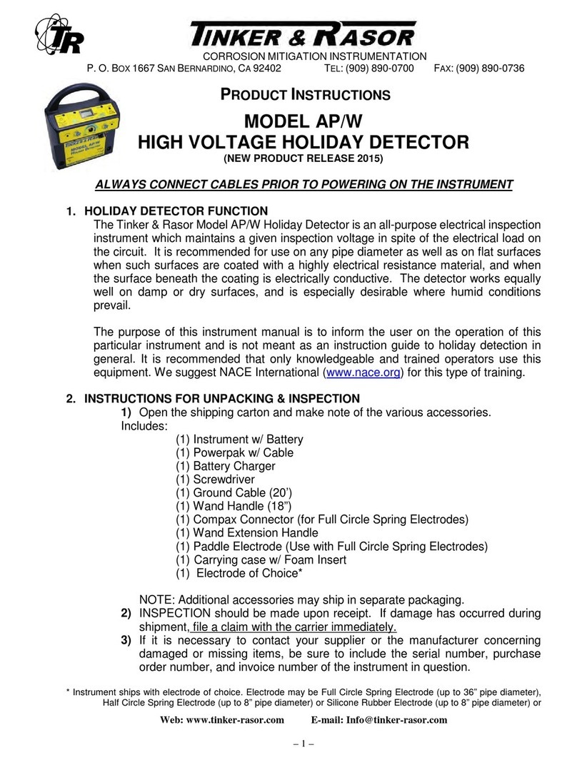
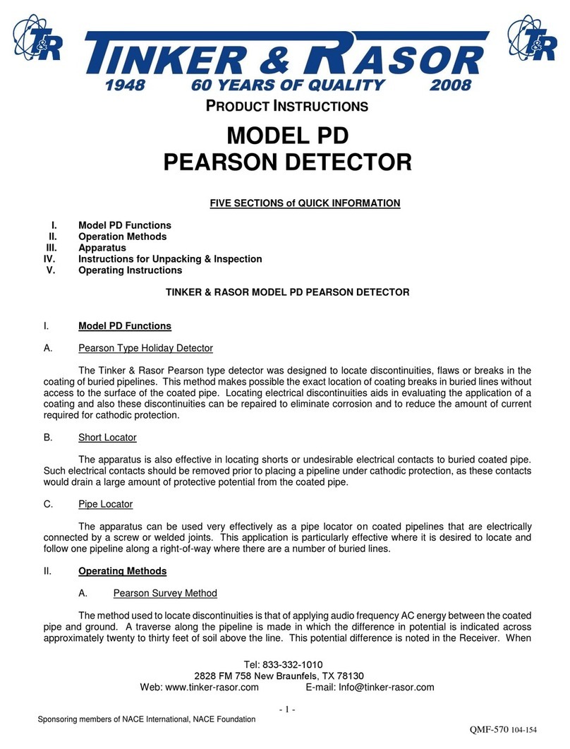
Tinker & Rasor AP/W User manual
Tinker & Rasor
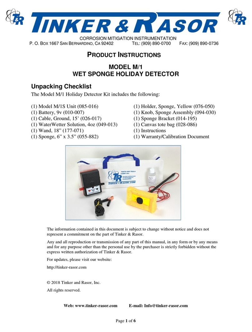
Tinker & Rasor PD Instruction sheet
Tinker & Rasor
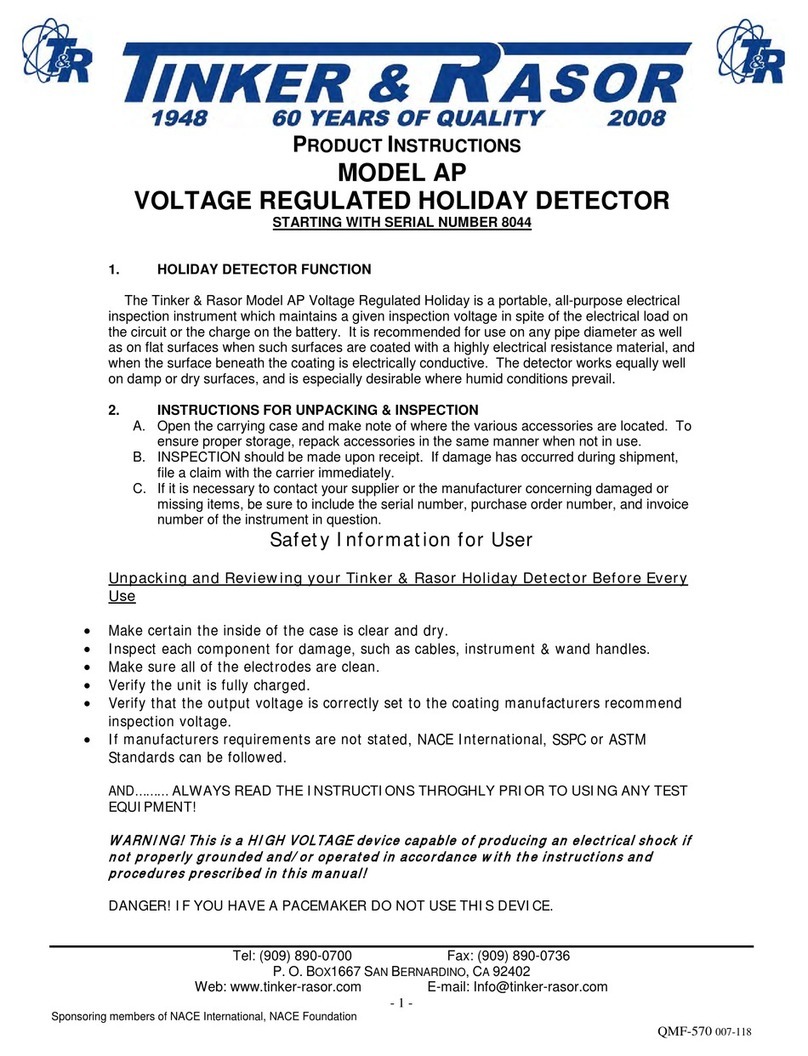
Tinker & Rasor M/1 Instruction sheet
Tinker & Rasor
Tinker & Rasor AP User manual
Popular Security Sensor manuals by other brands
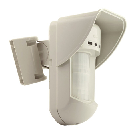
Risco
Risco WatchOUT installation instructions

ATP Electronics
ATP Electronics Heated Pentode ZX-1A owner's manual

TEUFELBERGER
TEUFELBERGER antiSHOCK Manufacturer's information and instructions for use
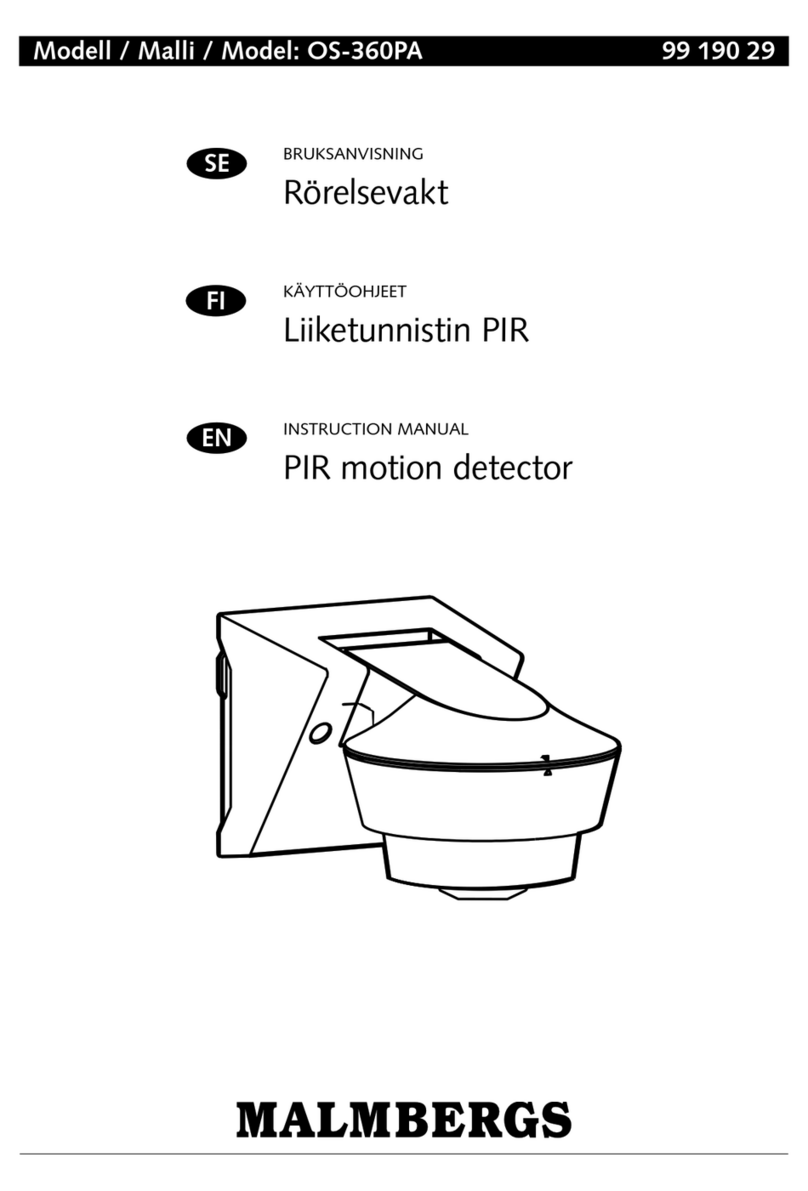
Malmbergs
Malmbergs OS-360PA instruction manual
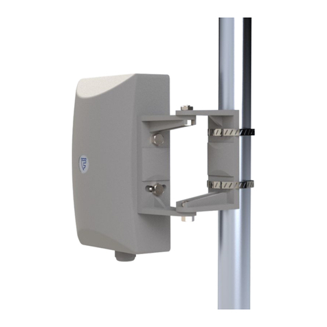
FORTEZA
FORTEZA FMC 24 Pro General description manual

Powerfix Profi
Powerfix Profi 285131 Operation and safety notes

Pilz
Pilz PSEN opII4H Series operating manual
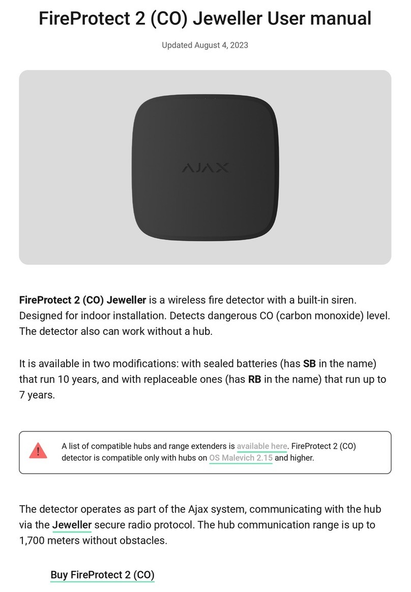
AJAX
AJAX FireProtect 2 (CO) Jeweller user manual
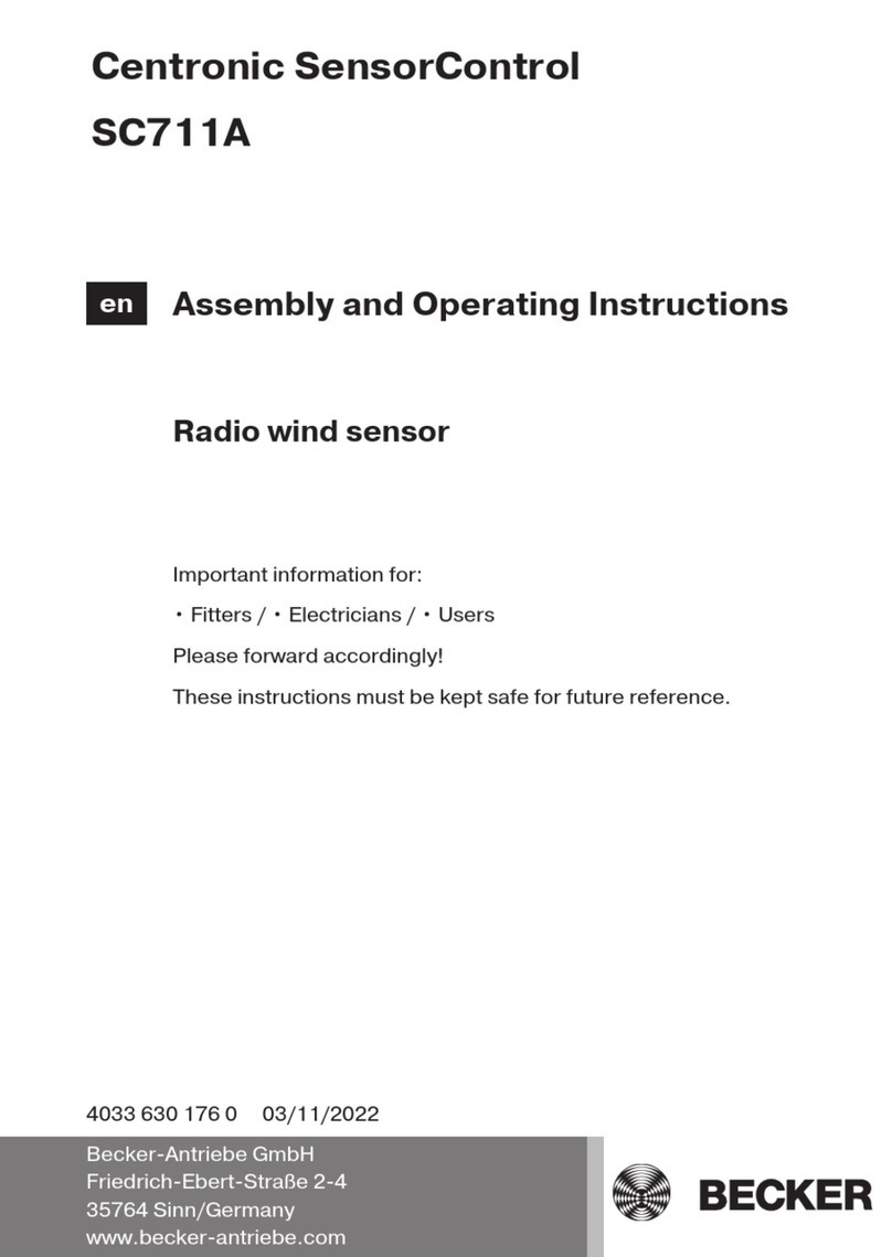
Becker
Becker Centronic SensorControl SC711A Assembly and operating instructions
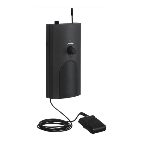
Transistor
Transistor Lynx manual
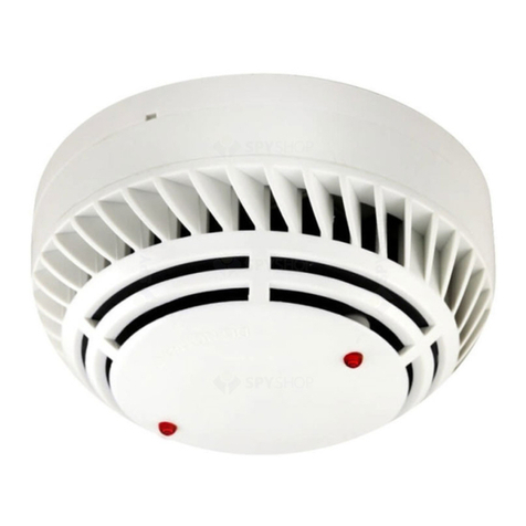
Global Fire
Global Fire ZEOS-AD-S quick start guide
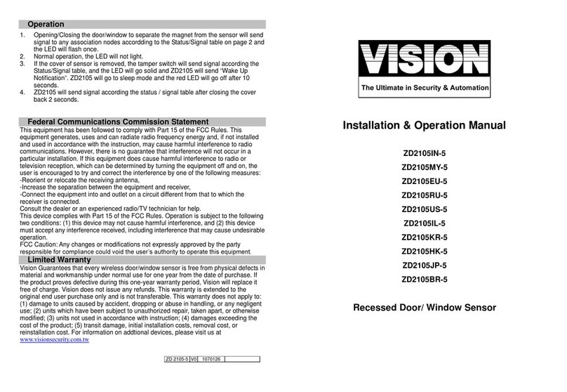
Vision
Vision ZD2105IN-5 Installation & operation manual
