TechniSat TECHNIVOLT 100 User manual

31
DE
EN
Installation
Instructions
Charging station for charging
electric vehicles
TECHNIVOLT 100 Plug socket model
TECHNIVOLT 101 Cable model
TECHNIVOLT

32
Table of contents
1 Introduction ......................................................................................................................... 33
2 Intended use ........................................................................................................................ 33
3 Safety instructions in this manual ................................................................................. 33
4 Safety instructions on the device .................................................................................. 34
5 General safety information.............................................................................................. 34
5.1 Safety instructions for the earthing system.........................................................................35
5.2 Safety instructions for mains cable, mains plug and charging cable .....................36
5.3 Safety instructions for wall mounting .....................................................................................36
6 Information about the charging station....................................................................... 36
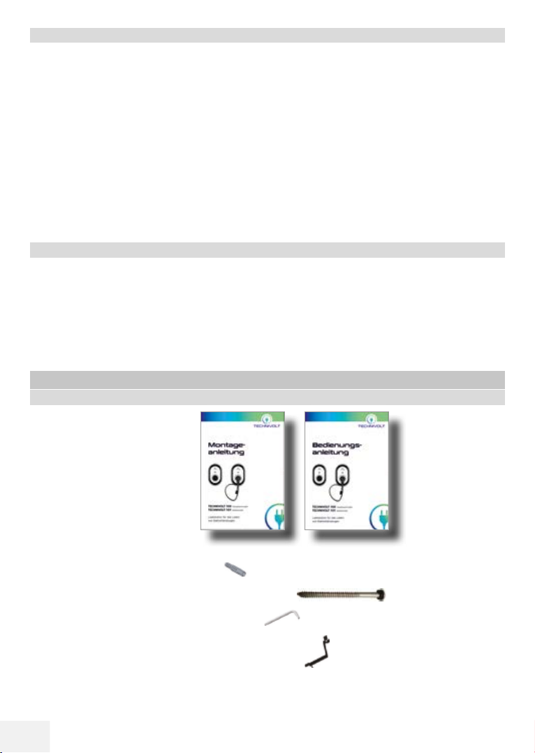
6.1 Scope of delivery................................................................................................................................36
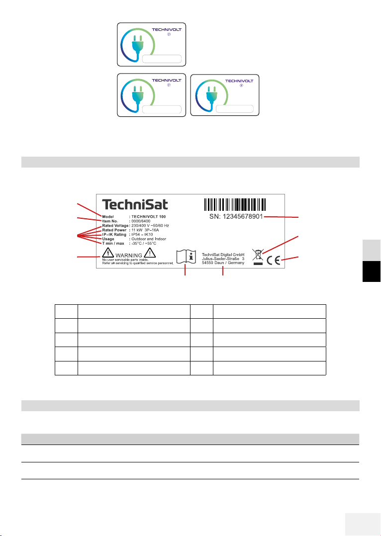
6.2 Type plate ..............................................................................................................................................37
6.3 Identification of the product variants .....................................................................................37
6.4 Operating elements and connections.....................................................................................38
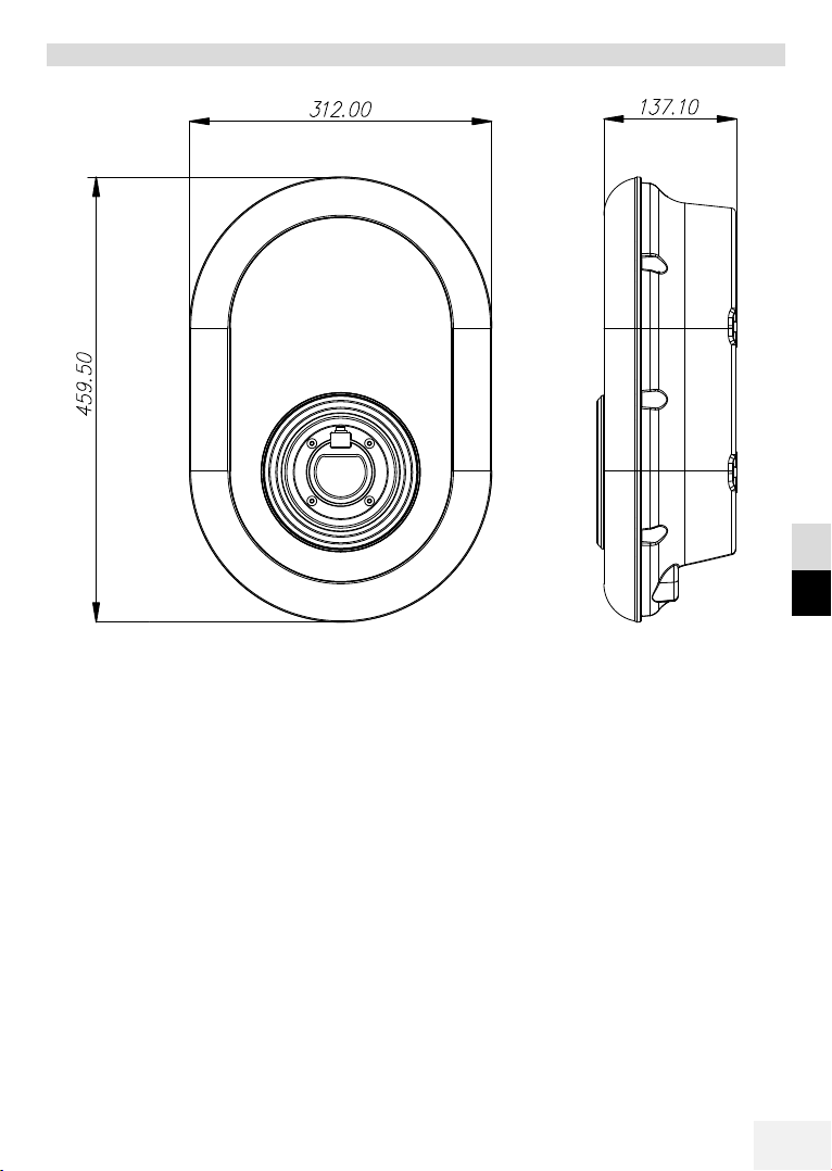
6.5 Device dimensions.............................................................................................................................39
7 Technical Specifications....................................................................................................40
7.1 General points.................................................................................................................................... 40
7.2 Input / power connection.............................................................................................................40
7.3 Output / vehicle connection........................................................................................................40
7.4 Fuses........................................................................................................................................................40
7.5 Authorisation.......................................................................................................................................40
7.6 Communication..................................................................................................................................40
7.7 Mechanical properties....................................................................................................................40
7.8 Operating conditions.......................................................................................................................40
7.9 Storage conditions ............................................................................................................................ 41
8 Installing the charging station.........................................................................................41
8.1 Recommended tools........................................................................................................................ 41
8.2 Installation steps................................................................................................................................ 41
8.2.1 Opening the cover on the charging station............................................................... 42
8.2.2 Wall mounting............................................................................................................................43
9 Connecting the charging station.................................................................................... 45
9.1 Mains connection...............................................................................................................................45
9.2 Data cable connection ....................................................................................................................47
10 Seings for the charging station ..................................................................................48
10.1 Seing the charging current ....................................................................................................... 48
10.2 Optional seings using a DIP switch....................................................................................... 49
10.2.1 Activating control of the external charging function (function ON / OFF) 49
10.2.22 Locked cable function (only TECHNIVOLT 100)..........................................................51
10.2.3 Intelligent charging control - load management.....................................................52
11 Load shedding ..................................................................................................................... 55
12 Monitoring welded relay contacts ................................................................................. 56
13 Shutdown and re-start of the charging station ......................................................... 57
14 Disposal ................................................................................................................................ 57
15 CE mark and declaration of conformity........................................................................ 58
16 Contact address .................................................................................................................. 58
17 Service instructions ........................................................................................................... 58
18 Copyright............................................................................................................................... 58

33
DE
EN
1 Introduction
These instructions describe the mechanical and electrical installation of the charging station
TECHNIVOLT 100 and TECHNIVOLT 101. It is addressed to a qualified electrician who, on
account of his technical training, knowledge and experience and knowledge of the applicable
standards can assess, execute and detect any possible dangers associated with the working
steps described in these instructions.
These operating instructions are an integral part of the product and must be kept safely for
its entire service life.
Please read these instructions in full before installation or commissioning.
2 Intended use
The charging station is designed exclusively for charging electric vehicles using charging mode 3
(Mode 3 in accordance with the standard IEC 61851-1. Connecting other devices is not permied.
Intended use of this device always includes compliance with the operating instructions.
3 Safety instructions in this manual
The following symbols and warning instructions are used in this manual and they must be
observed.
Warns about electric danger
Disconnect the power before working.
WARNING
Indicates a dangerous situation that can lead to death or severe injury if it is
not avoided.
DANGER
Indicates a danger that can lead to death or severe injury if it is not avoided.
NOTE
Indicates important information and special features.
CAUTION
Indicates dangers that can lead to damage to the device itself or to other
electrical consumers.

34
4 Safety instructions on the device
Safety signs are mounted on the charging station and must be complied with.
Read the installation instructions before you open the charging station or start
installation of the charging station.
A dangerous electrical voltage may be present inside the charging station aer
opening the housing.
5 General safety information
For your own protection, please read through the safety instructions carefully prior to installation.
• Keep these installation instructions safe. These safety and installation instructions must be
kept in safe keeping for consultation at a later date.
DANGER
Danger to life from electrical power.
All assembly and installation work should be carried out by an expert electrician.
A skilled person is someone who, on account of their technical training and
experience, has adequate knowledge in the field of the installation to be
tested, and who is acquainted with the applicable governmental safety at
work regulations, accident prevention regulations, guidelines and the generally-
accepted rules of technology (e.g. DIN standards, VDE stipulations) to an extent
that he can assess the safe working status of the installation. Skilled persons
can be persons such as works engineers, master crasmen, technical sta
and fiers.
The person carrying out the installation must be fit for the work involved in
accordance with DGUV Regulation 103-011 “Working on live electrical systems
and operating material”.
WARNING
Never permit persons (including children) with limited physical, sensoral or
mental capacities, or with a lack of experience and / or knowledge to use the
electrical equipment unsupervised!
Non-observance of these warnings can lead to death and severe injury.
NOTE
The alternating current mains connection and the loading plan for the charging
station for electric vehicles must be checked and approved by the authorities
in accordance with the applicable regional or national regulations and
standards for electric vehicles. The loading plan must be created accordingly
for installations with several charging stations for electric vehicles. The
manufacturer is not liable, either directly or for any other reason, for damage
and risks produced by errors caused by the mains connection or load planning.

35
DE
EN
• Check the voltage stated on the type plate and use the charging station only with a suitable
power supply voltage.
• Do not continue using the device if you are unsure whether it is functioning correctly, or
may be damaged - switch it o and set the main power circuit breaker and residual current
device to OFF. Contact your local dealer.
• The ambient temperature must be between –35 °C and +55 °C, without direct sunlight, and
relative humidity must be between 5 % and 95 %. The charging station must be only used
within these operating conditions.
• The device must be located in a position that avoids excessive heating up of the charging
station. High operating temperatures, caused by direct sunlight or sources of heat, can
reduce the charging current or can temporarily interrupt the charging process.
• The charging station is designed for both outdoor and indoor use.
• In order to reduce the danger of fire and the danger of electrocution or product damage,
do not expose the device to rain, snow, thunderstorms or other severe weather events. In
addition, the charging station must not be exposed to spillages or sprayed fluids.
• Do not touch the connection terminals, the electric vehicle plug and all other live parts on
the charging station with sharp metal objects.
• Avoid contact with sources of heat and locate the device at a safe distance from flammable,
potentially explosive, reactive, and combustible materials, chemicals and vapours.
• Explosion risk This device has parts within it that may cause electric sparks and discharges
and which should never come into contact with flammable vapours. It must not be installed
in recesses or cellar rooms.
• The device is intended only for the charging of electric vehicles whose charging can be
carried out without ventilation.
• In order to prevent the danger of an explosion or electrocution, make sure that the stipulated
line protection switch and the ground fault circuit interrupter are correctly connected to
the electric mains in the building.
• The boom of the charging plug socket (TECHNIVOLT 100) should be located at a height of
1 m to 1.5 m above floor level.
• One must not use adapters or conversion adapters. Cable extension leads must not be used.
• The charging station must not be installed in areas where there is a danger of high water.
5.1 Safety instructions for the earthing system
• The charging station must be connected to a centrally earthed system. The earth line that
goes into the charging station must be connected to the grounding lug of the device. This
must be carried out with power circuit conductors while connected to the earthing rail of the
device or on the charging station. Connection to the charging station is the responsibility
of the installer and the purchaser. In order to reduce the danger of electrocution, connect
the device using only properly earthed plug sockets.
WARNING! Make sure that the charging station is constantly and properly earthed during
installation and use.

36
5.2 Safety instructions for mains cable, mains plug and charging cable
• Make sure that the charging cable at the side is compatible with the charging station.
• A damaged charging cable can cause fires or electrocution. Do not use this product if the
flexible charging cable or the vehicle cable is frayed, has damaged insulation, or displays
other indications of damage.
• Make sure that the charging cable is positioned in such a way that nobody can step on it
or trip over it, and that it is neither damaged nor over-stretched.
• Never forcefully pull on the charging cable and do not damage it with sharp objects.
• Never touch the mains cable or the plugs with wet hands since this may cause a short-
circuit or electrocution.
• In order to avoid the danger of fire or electrocution, the device must not be used with
extension cables. If the mains cable or the vehicle charging cable are damaged, they must
be replaced by the manufacturer, his customer service engineers or a similarly qualified
person in order to avoid hazards.
5.3 Safety instructions for wall mounting
• Do not install the charging station on the ceiling or an inclined wall.
• The charging station must only be operated when mounted vertically.
• The charging station must not be installed in enclosed cabinets.
• Use only the screws and accessories provided for wall mounting
• The device is designed for use indoors and outdoors. If the device is to be installed outdoors,
all the connection devices for outdoor operation must be designed and properly installed
so as to ensure that the prescribed IP protection rating is retained.
6 Information about the charging station
6.1 Scope of delivery
1 TECHNIVOLT charging station
1 set of assembly instructions
1 instruction manual
1 installation template
1 set of installation accessories:
• 4 plastic plugs, M8 x 50 mm
• 4 safety screws, Torx T25, M6 x 75 mm
• 1 safety angle wrench, Torx-TR 20
• Wrenches for cable connections M20 and M32

37
DE
EN
1 Master RFID card
2 user RFID cards
6.2 Type plate
The type plate is located on the right-hand side of the charging station. The following image
shows all details on the type plate.
Illustration1:Type plate
❶Product designation ❻Distributing company
❷Item number ❼CE marking
❸Technical data ❽Disposal instructions
❹Safety advice ❾Serial number
❺Read the installation instructions
6.3 Identification of the product variants
The article number is relevant for identification of the charging station (see IllustrationIllustration1,
No. ❷❷).
Item number Designation Variants
0000/6400 TECHNIVOLT 100 An 11 kW charging station with integrated charging plug socket built in
accordance with IEC 62196-2 Type 2
0000/6401 TECHNIVOLT 101 An 11 kW charging station with charging cable firmly connected built in
accordance with IEC 62196-2 Type 2
MASTER
Privates Laden
BENUTZER
Privates Laden
BENUTZER
Privates Laden
❶❶
❷❷
❸❸
❹❹
❻❻
❼❼
❺❺
❽❽
❾❾

38
6.4 Operating elements and connections
TECHNIVOLT 100
With integrated charging plug socket
TECHNIVOLT 101
With charging cable firmly connected
❶❶
❷❷
❸❸
❹❹
❻❻❼❼
Illustration2:TECHNIVOLT 100
❶❶
❷❷
❸❸❺❺
❹❹
❻❻❼❼❽❽
Illustration3:TECHNIVOLT 101
❶LED status indicator ❶LED status indicator
❷RFID reader ❷RFID reader
❸Charging plug socket type 2 ❸Charging plug type 2
❹Type plate ❹Type plate
❺-❺Blind socket for charging plug
❻Input AC infeed, M32
M32 bushing ❻Input AC infeed,
M32 bushing
❼Input communication cable,
M20 bushing ❼Input communication cable,
M20 bushing
❽Charging cable

39
DE
EN
6.5 Device dimensions
Illustration4:Device dimensions

40
7 Technical Specifications
7.1 General points
Model TECHNIVOLT 100 TECHNIVOLT 101
Item number: 0000/6400 0000/6401
EAN 4019588064003 4019588064020
IEC protection class Class l Class l
7.2 Input / power connection
Nominal voltage 230 / 400 V 230 / 400 V
Nominal current rating 16 A, 3-phase 16 A, 3-phase
Rated frequency 50 / 60 Hz 50 / 60 Hz
Power consumption on
standby
3.5 W 3.5 W
Mains infeed 5 x 4 mm (< 50 m), 15-21 mm dia. 5 x 4 mm (< 50 m), 15-21 mm dia.
7.3 Output / vehicle connection
Charging operating mode Mode 3, IEC61851-1 Mode 3, IEC61851-1
Charging connection Plug socket type 2, IEC-62196 Charging cable 5m with type 2
coupling. IEC-62196-2
Output voltage 230 / 400 V 230 / 400 V
Maximum charging current 16 A per phase 16 A per phase
Maximum charging power 11 kW 11 kW
7. 4 Fuses
DC residual current detection RCM internal, In ≥ 6 mA RCM internal, In ≥ 6 mA
Line protection switch (MCB)
in input / power connection
Trigger characteristics C
For details, see Chapter 10.1
Trigger characteristics C
For details, see Chapter 10.1
Ground fault circuit interrupter
(RCCB) in input/power
connection
4P-20A-30mA, type A 4P-20A-30mA, type A
7.5 Authorisation
RFID ISO-14443A/B and ISO-15693 ISO-14443A/B and ISO-15693
7.6 Communication
Data interface RS484, Modbus RS484, Modbus
7. 7 Mechanical properties
Casing material Plastic, flame-resistant Plastic, flame-resistant
Bushing for mains infeed M32, for cable 15-21 mm dia. M32, for cable 15-21 mm dia.
Bushing for data cable M20, for 2 cables Ø M20, for 2 cables Ø
Weight device 4.315 kg
Device dimensions 315 mm (width) x 460 mm (height)
x 135 mm (depth)
315 mm (width) x 460 mm
(height) x 135 mm (depth)
Weight, including packaging 6.315 kg
Packaging dimensions 398 mm (width) x 520 mm (height)
x 237 mm (depth)
398 mm (width) x 520 mm
(height) x 324 mm (depth)
7.8 Operating conditions
Protection class IP54 IP54
Impact resistance IK10 IK10
Temperature -35 °C to 55 °C (without direct
sunlight)
-35 °C to 55 °C (without direct
sunlight)

41
DE
EN
Humidity 5 % to 95 % (relative, non-
condensing)
5 % to 95 % (relative, non-
condensing)
Operating height 0 to 4,000 m above Sea level 0 to 4,000 m above Sea level
7. 9 Storage conditions
Temperature -40 °C to 80° C (without direct
sunlight)
-40 °C to 80° C (without direct
sunlight)
Humidity 5 % to 95 % (relative, non-
condensing)
5 % to 95 % (relative, non-
condensing)
Operating height 0 to 5,000 m above Sea level 0 to 5,000 m above Sea level
8 Installing the charging station
8.1 Recommended tools
Drill bit, 8 mm dia. Hammer drill Spirit level
Voltmeter Torx-TR 25 safety
screwdriver
EVC tester
Screwdriver
(width 2-2.5 mm) Centrepunch or pencil Angle adapter hex-bit
& Torx-TR 20 safety bit
Table 1:Recommended tools
8.2 Installation steps
CAUTION!
• Make sure that the earthing resistance of the installation is less than 100 Ohms
• Read these instructions before mounting your charging station on the wall.
• Do not install the charging station on the ceiling or an inclined wall.
• Use only the screws and accessories provided for wall mounting
• This charging station is designed for installation indoors and outdoors. If the device is
installed outside the building, the hardware used to connect the cables to the charging
device must be compatible with outdoor use, and the charging station must be installed
in such a way that the IP54 protection rating is retained.

42
8.2.1 Opening the cover on the charging station
Illustration 5:Opening the charging station
DANGER
Danger to life from electrical power.
There is an immediate danger to life by electrocution if you touch live parts.
De-energise the installation before starting work.
Observe the 5 safety rules to prevent electrical accidents.
• Release.
• Secure against restarting.
• Validate that the power is o.
• Earth and short-circuit.
• Cover or cordon o any adjacent live parts.
Open the charging station as described in Illustration .
1. Remove the cover screws using the Torx TR 20 safety angle wrench or the
angle adapter with the Torx TR 20 safety bit.
2. Open the cover.
1 2
❶❷

43
DE
EN
8.2.2 Wall mounting
Illustration6:Wall mounting
AC power
infeed
Key
Control cable
(option)
❼❼
❻❻
Before taking the next step (❼), read the instructions in
Chapter „9 Connecting the Charging Station“, Page 45.
Key
❶❶❷❷
❸❸
❹❹
❺❺

44
Illustration7:Wall mounting
1. Open the front cover on the product in accordance with the instructions in „8.2.1 Opening
the cover on the charging station“, Page 42.
2. Centre the charging station with the aid of the drilling template and mark the holes with a
pencil.
3. Drill the wall at the marked points using the hammer drill (8 mm drill bit).
4. Insert the plugs into the holes.
5. Tighten the safety screws (M6 x 75) on the product using the Torx TR 25 safety screwdriver.
6. Direct the open connection cables through the hole on the le at the boom into the charging
station. Follow the instructions for establishing a mains connection (see Section 9.1) and
seing the charging current (see Section 10.1).
7. Tighten the cable screwed connections as shown in the figure. Before closing the cover on the
charging station, follow the instructions in Chapter „10 Seings for the Charging Station“, Page
48 and in the following sections from there if using functions with reference to these sections.
8. To close the cover on the charging station, tighten the previously removed cover screws using
the Torx TR20 safety angle wrench, or the right-angle angled adapter hexagon bit with the
Torx TR20 safety bit.
9. The installation of the charging station on the wall is now complete.
Before closing the cover on the charging station, follow the instructions
in Chapter „10 Seings for the Charging Station“, Page 48 and in the
following sections from there if using functions with reference to
these sections.
❽❽
❽❽❾❾

45
DE
EN
9 Connecting the charging station
The following chapter describes the 3-phase mains connection of the charging station.
9.1 Mains connection
You must dimension the mains infeed at least as described in Chapter „7 Technical Specifications“,
Page 40. The outside diameter of the mains infeed line must be between 15 mm and 21 mm.
1. Guide the cables into the device and the terminal rail as shown in Figure Illustration .
2. Tighten the screws on the terminal rail as shown in Figure Illustration to a tightening torque
of 2.5 Nm.
Illustration 8:Mains connection, 3-phase
DANGER
Danger to life from electrical power.
There is an immediate danger to life by electrocution if you touch live parts.
De-energise the installation before starting work.
Observe the 5 safety rules to prevent electrical accidents.
• Release.
• Secure against restarting.
• Validate that the power is o.
• Earth and short-circuit.
• Cover or cordon o any adjacent live parts.
1
1
2
❶❶
❷❷
❶❶

46
The individual wires in the mains infeed must be connected to the terminal rail as described
in the following .
Mains connection terminal
No.
Cable colour, mains infeed
3-phase 1-phase
1 L3 (grey)
2 L2 (black)
3 L1 (brown) L1 (brown)
4 Neutral wire (blue) Neutral wire (blue)
5 Protection wire (green-
yellow)
Protection wire (green-
yellow)
Table 2:Mains connection
NOTE
The standard charging current is set to 16 A
Changing the charging current is described in Chapter „10.1 Seings for the
Charging Current“, Page 48.
NOTE
The charging station can also be connected with a single phase. The maximum
charging power then is 3.7 kW (230 V x 16 A x 1).
We recommend a 3-phase connection to the charging station in order to
achieve the maximum charging power of 11 kW (230 V x 16 A x 3).

47
DE
EN
9.2 Data cable connection
Illustration9:Figure 8
1. Remove the rubber closure.
2. Guide the cable through the cable opening.
3. Guide the cable through the openings in the holding bracket (as shown in the photograph).
4. Follow the additional information in chapters 10.2.1, 10.2.3, 11 or 12 to connect the wires,
depending on the function(s) to be used.

48
10 Seings for the charging station
10.1 Seing the charging current
The charging current on the charging station must be set in accordance with the line fuse in
the building. The charging current is set using the rotary knob SW2.
The arrow in the centre of the rotary knob SW2 (see Illustration ) is set to the desired current
level position by carefully turning it with a flat screwdriver (tip width 2.0-2.5 mm) (see Tabelle 3).
The standard charging current is set to 16 A.
Illustration10: Rotary knob SW2 for charging current seing
CAUTION
Power line overload.
The charging current should never be set higher than the rating of the line fuse.
Position
SW2
Current threshold
Phase Power Power
rating
0
1-phase
10 A 2.3 kW
1 13 A 3 kW
2 16 A 3.7 kW
3 -
4 -
5 -
6 -
7 -
8
3-phase
10 A 6.9 kW
9 13 A 9 kW
A 16 A 11 kW
B -
C -
D -
E -
F -
Table3:Seing the charging current
The prescribed line protection switch in
the AC power infeed
Rotary knob SW2 set to MCB, C curve
10 A 13 A
13 A 16 A
16 A 20 A
Table4:Dimensioning the line protection
switch

49
DE
EN
10.2 Optional seings using a DIP switch
Optional functions of the charging station can be activated using a DIP switch. The DIP switch
is located on the PCB in the charging station.
Illustration.11: DIP switch on the PCB
The descriptions of the DIP switch seings are given in the following table.
Switch number Description
1 RFID Master and user card reset
2 „Activating control of the external charging function (function ON/)“, Chapter 10.2.1
3 „Locked cable function (only TECHNIVOLT 100)“, Chapter 10.2.2
4 / 5 / 6 „Intelligent charging control - load management“, Chapter 10.2.3
Table 5: DIP switch
10.2.1 Activating control of the external charging function (function ON/OFF)
Your charging station has an external potential-free activation/deactivation function which can
be used for integration of your charging station in a multi-storey carpark automation system,
ripple control receivers for energy suppliers, timers, photovoltaic power inverters, auxiliary load
check switches, external key-switches etc. DIP switch no. 2 serves to activate and deactivate
this function.
Illustration 12:DIP switch no. 2

50
You can connect potential-free input signals as shown in Illustration.13.
Illustration13:Function circuit “External Charging Function”
Connecting the control line to the charging station is carried out as follows Illustration .
NOTE
Introduction pf the control line into the charging station is described in Chapter
„9.2 Data cable connection“, Page 47.
Illustration14:Cable connection "External Charging Function"
Cable connection Cable colour
1 (CN2-1) Green
2 (CN2-2) Green + white green
Table6:Cable connection "External Charging Function"
1
CN2
EVSE RL
1
4
2
3
2
TECHNIVOLT
Charging
station
External
Switching unit
This manual suits for next models
3
Table of contents