TECHNO-AC TDR-TA3.3T User manual

Cable fault locator
TDR-TA3.3T
USER MANUAL

Cable fault locator TDR-TA3.3T
________________________________________________________________________
________________________________________________________________________
2
Contents
Introduction.........................................................................................................................4
1Device application area and its distinction from a previous model TDR-TA3.3T...........5
2Basic technical specifications and characteristics.........................................................6
3 Devise and delivery set ................................................................................................8
4The TDR-TA3.3T structure and functioning...................................................................9
4.1 Operation method...................................................................................................9
4.2 Design ..................................................................................................................11
5Security measures.......................................................................................................15
6Use preparation and operating procedure...................................................................15
6.1 Pre-operation test.................................................................................................15
6.2 Switching-on of the device....................................................................................15
6.3 Device connection to the researched line.............................................................15
6.4 Measuring the length of the researched line.........................................................16
6.5 Measuring the coefficient of line shortening at its known length...........................17
6.6 Measuring the distance to the irregularity of the researched line.........................18
6.7 Analysis of the specific irregularities of the researched line..................................18
6.8 Setting-up of the distance reference point............................................................20
6.9 Set up of the window (subrange) offset to the beginning of measurements .........20
6.10 Manipulation with a nonvolatile device memory....................................................21
6.11 Battery control.......................................................................................................21
6.12 Shutting down the device display's lighting...........................................................21
6.13 Switching-of the TDR-TA3.3T...............................................................................21
7Potential faults and their elimination............................................................................21
8Technical support........................................................................................................22

Cable fault locator TDR-TA3.3T
________________________________________________________________________
________________________________________________________________________
3
9Device calibration........................................................................................................22
10 Transportation and storage .........................................................................................23
11 Marking .......................................................................................................................23
12 Acceptance and packaging certificate.........................................................................24
13 Warranty obligations....................................................................................................25

Cable fault locator TDR-TA3.3T
________________________________________________________________________
________________________________________________________________________
4
Introduction
This User Manual (UM) is a document certifying the basic parameters guaranteed
by the manufacturer and technical characteristics of the cable fault locator TDR-TA3.3T.
Warranty terms do not cover the cases of misuse of the device or use of the
device not in accordance with the rules listed in a given UM.
UM is intended for acquaintance with the TDR-TA3.3T device and the principle of
operation and sets the operating rules, compliance with which maintains the device in
constant readiness for action.
Persons with secondary technical education are admitted to work with the device,
with experience in electrical appliances for general purposes.

Cable fault locator TDR-TA3.3T
________________________________________________________________________
________________________________________________________________________
5
1 Device application area and its distinction from a previous
model TDR-TA3.3T
1.1 The device TDR-TA3.3T is significantly improved in contradistinction to TDR-
TA3.3T in the following issues:
the device memory maintains an option of saving one waveform due to compare
it with the next waveform.
the device input bandwidth is significantly expanded, that allows to work in
narrow areas and to distinguish closely located faults on a 1,5 –2 meter
distance between them.
1.2 The TDR-TA3.3T is intended for the following measurements on symmetric and
asymmetric cables with wave impedance from 30 to 400 Ohm:
measuring the cable length;
measuring the distance to wave impedance irregularities or defects;
measuring the coefficient of a line shortening at its known length;
definition of nature of damage;
display of the measurement results on LED-screen with 320*240 pcs definition;
results saving;
1.3 The TDR-TA3.3T is a compact device, intended to operate in field and stationary
conditions.
Climatic performance type TDR-TA3.3T group 4 GOST 22261
operational range of temperature from –20 to +40 °С;
relative humidity 98% at 25 °С above zero;
transportation and storage terms from –50 to + 50 °С.
1.4 The TDR-TA3.3T is durable and resistant to sinusoidal vibration exposure according
to a group 4 GOST 22261 in the frequency range from 10 to 55 Hz.
The TDR-TA3.3T power is supplied from four AA-batteries of 2700 mA*Hr capacity.
The TDR-TA3.3T design provides a battery discharge control and automatic
disconnection of the device after 10 minutes down time (not-pressed buttons).
1.5 TDR-TA3.3T produces no noise.

Cable fault locator TDR-TA3.3T
________________________________________________________________________
________________________________________________________________________
6
2 Basic technical specifications and characteristics
2.1 Distance measurement range (time delay range) from 0 to 4800 m (0-48 µs).
Measurement subranges (windows): 30 m, 60 m, 120 m, 240 m, 480 m, 960 m, 2400 m,
4800 m.
2.2 Distance measurement permissible basic reduced error limits (time delay) in the
subranges (windows) ±0.42% of the subrange (window) final value.
2.3 Distance measurement permissible basic reduced error limits (time delay) in the
operation temperatures range from –20 to + 40 °С ±0,84% of the subrange (window) final
value.
2.4 The parameters of a positive polarity probe pulse are given in the Table 1 and on
the Picture 2-1.
Рисунок 2-1
Picture 2-1

Cable fault locator TDR-TA3.3T
________________________________________________________________________
________________________________________________________________________
7
Table 1
Probe pulse
parameters
10
ns
20
ns
50
ns
100
ns
200
ns
500
ns
1
µs
2 µs
5 µs
10
µs
τи, µs
≤
0,01
≤
0,02
≤
0,05
0,1 ±
0,01
0,2 ±
0,02
0,5 ±
0,05
1,0 ±
0,01
2 ±
0,2
5 ±
0,5
10 ±
1,0
н, ns,
not more than
10
10
10
10
10
10
10
10
10
10
U, В,
not more than
9,0
9,0
9,0
9,0
9,0
9,0
9,0
9,0
9,0
9,0
2.5 Permissible relative error parameters of the shortening coefficient within the range
of 1 to 3 ± 0,84%.
2.6 Receiving path sensitivity when the signal exceeds the noise level twice on all the
subranges (windows) should be not less than 1 mW.
2.7 Agreed resistances range is from 30 to 400 Ohm.
2.8 Operation mode time set up is not more than 30 sec.
2.9 Continuous running TDR-TA3.3T from ACC1 battery is not less than 8 hours and
depends on the technical condition of battery.
2.10 The TDR-TA3.3T overall dimensions are not more than:
length –230 mm
width –130 mm
height –50 mm
2.11 The TDR-TA3.3T weight without removable batteries does not exceed 0,55 kg.
2.12 Safety
2.12.1Average operation time before technical resource exhaustion should be not less
than 6000 hours.
2.12.2Fixed service life should be not less than 5 years.

Cable fault locator TDR-TA3.3T
________________________________________________________________________
________________________________________________________________________
8
3 Product and delivery set
The TDR-TA3.3T delivery set consists of:
domain reflectometer TDR-TA3.3T - 1 item
connecting cable - 1 item
Ni-Mh AA battery 1,2 W 2700 А*Hr - 4 items
charger - 1 item
carrying strap - 1 item
User Manual - 1 item

Cable fault locator TDR-TA3.3T
________________________________________________________________________
________________________________________________________________________
9
4 The TDR-TA3.3T structure and functioning
4.1 Operating principle
The device operating principle implements the method of pulse-refletometry that is
based on the phenomenon of partial reflection of electromagnetic waves in places of
change of circuit wave impedance. When measured by the impulse method, the
rectangular probe pulse is being sent to the line. The pulse partially reflects from the
irregularities and returns. The probe and reflected pulses are being observed on the
screen scalable in distance and amplitude. The shape of pulses allows the user to
evaluate the line irregularity type (see Picture 2). The reflected pulses return to the device
in some time from the moment of sending the probe pulse. Knowing the electromagnetic
wave propagation speed along the line and the reflected signal delay time, the user can
calculate the distance to the irregularity of the wave impedance.
3
322 t
CS
Сt
where X –the distance to irregularity, m;
v –electromagnetic wave propagation velocity inside the line, m/µs;
t3 –reflected signal delay time, µs
v = s/CS
s –speed of light, equal to 300 m/µs;
CS –coefficient of shortening.
Impedance irregularities are the result of violations of manufacturing technology of
cables as well as a consequence of mechanical and electrical hazards during the
construction and operation of the cable lines. Irregularity of the line impedance appears in
the connection points of some devices and the line (couple, split, joint, Pupin coil, etc.) or
in hazard points (break, short circuit, cable core wetting, ground leakage, leakage over the
Cable fault locator TDR-TA3.3T
________________________________________________________________________
________________________________________________________________________
10
neighbor cable etc.). TDR method allows to fix multiple irregularities both discrete and
lengthy, depending on the ratio of their length and the minimal wavelength of the spectrum
of the probe pulse.
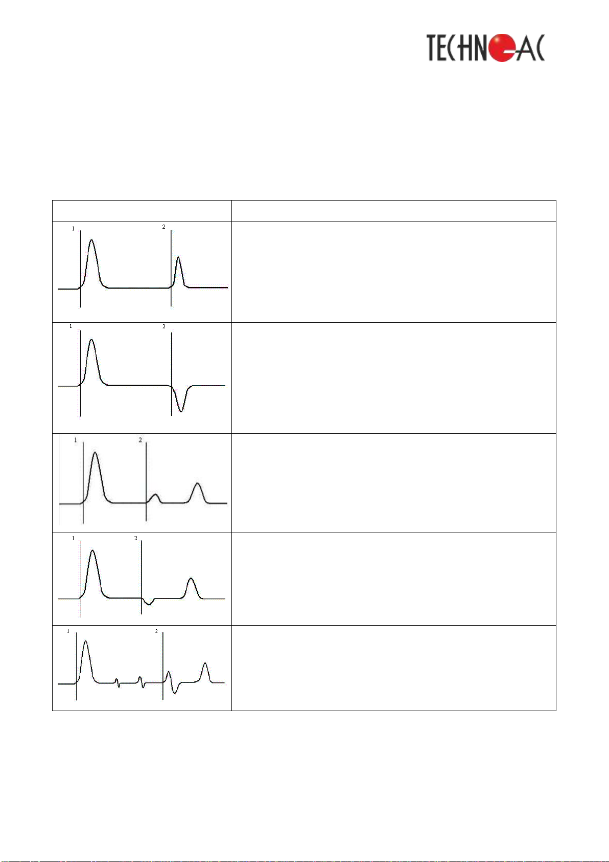
Table 2 Waveforms of typical irregularities
Type of waveform
Description
The waveform depicts the case of the signal reflection from the point of a
high resistance (the second cursor), that means a cable breakage. The
condition showed in the waveform is called after typical breakage.
The reflection with a signal polarity change is equivalent to a short circuit in
cable, to a small resistance of irregularity. Such a condition is called after a
typical short circuit.
The given waveform shows the partial breakage option (the second cursor)
followed by the complete breakage.
The waveform describes the case of a partial breakage marked with the
second cursor, followed by the complete breakage of cable.
The given waveform shows three cable solderings. The soldering marked
with the second cursor is damaged. The irregularity reflection level depicts it
good.

Cable fault locator TDR-TA3.3T
________________________________________________________________________
________________________________________________________________________
11
COMMENT: The pulse amplitudes are given in the related proportions with the
same amplification.
The pulse of a positive polarity with the amplitude not less than 10 W is used as a
probe pulse. The probe pulse endurance is to be selected out of the given row: 10 ns, 20
ns, 30 ns, 50 ns, 100 ns, 200 ns, 500 ns, 1 µs, 1,5 µs, 3 µs, 5 µs, 10 µs –for every
subrange (window) of measurement.
The coefficient of shortening value is individual for every type of cable. It is
connected with the type of the cable jacket as follows:
0
CS
where ε0–dielectric constant cable sheath
The value of coefficient of shortening can be defined experimentally, knowing the
length of cable.
The error of the distance to irregularity is to be defined with discreteness of the
indicator (320 discretes/scale) and with the error of the line shortening coefficient (CS)
setting-up. Furthermore there can appear extra errors because of the form of reflected
signal deformation inside the lines with frequency-depended losses.
The measurement error can be also caused by the type of irregularity, the error
value, presence of several irregularities inside the line. The measurement error can be
reduced with the alignment of the device with the line via “COORD.”.
The TDR-TA3.3T allows to determine the distance automatically (depending on the
selected coefficient of shortening). The distance is equivalent to the cursor location on the
screen and is being displayed digitally at the bottom of the screen next to the cursor
location.
Cable fault locator TDR-TA3.3T
________________________________________________________________________
________________________________________________________________________
12
Design
The design of the device is given on the Picture 4-1.
Picture 4-1. The TDR-TA3.3T design
4.2 The control and displaying tools (keyboard, grips) location and function.
4.2.1 Power supply
The power supply of the device is provided with four built-in batteries AA 1,2 W
2700 A*Hr. The device is being turned on with the “ON/OFF” button. The battery charging
process is given in the issue 8.4.
4.2.2 The SECURITY button with the green luminous indicator is used for switching on/off
the circuit board of measuring connectors of the device (see issue 6.3).

Cable fault locator TDR-TA3.3T
________________________________________________________________________
________________________________________________________________________
13
4.2.3 The connector LINE is intended to connect the cables in MEASUREMENT mode
(see issue 6.3).
4.2.4 A “COORD”. grip is used only in the MEASUREMENT mode for the TDR-TA3.3T
output resistance and the wave resistance of the researched cable coordination. The
minimal magnitude of the amplitude of multiple resampled signals is the most appropriate
coordination criterion. It is recommended to use the buttons « » and « » with the
“COORD.” grip at the same time due to obtain the maximal image frequency (see issue
6.4.6).
4.2.5 The “PULSE” button is used for a quick transition to the “PULSE” selector (see issue
6.4.1).
4.2.6 The “WINDOW” button is used for a quick transition to the “Window” selector, for a
measurement window (subrange) adjustment (see issue 6.4.2).
4.2.7 The “LIGHT” button is used for a quick switching on/off of the device display’s
lightning (see issue 6.12).
4.2.8 The “GAIN” button is used for a quick transition to the “Intensification” selector, for
the gain factor adjustment (see issue 6.4.3).
4.2.9 The “OFFSET” button is used for a quick transition to the “displacement” selector
due to adjust the vertically offset of the waveform chart (see issue 6.4.4).
4.2.10 The “Coefficient of shortening” («КУ») is used for a quick moving to the “Coefficient
of shortening” selector due to adjust the coefficient of shortening (see issue 6.4.5).
4.2.11 The « » button is used to move a measurement window (subrange) to the
beginning of measurements (see issue 6.9).
4.2.12 The « » button is used to give a currently located cursor a zero distance (see
issue 6.8).
4.2.13 The « » in MEASUREMENT mode selects the memory menu mode, points:
“EXIT” – exit from function, “Exit from memory” – waveforms exit from the memory (the
“memory” title appears in the right corner), “To memory” – saving a current waveform to
the memory.
4.2.14 The «» and « » buttons in MEASUREMENT mode is used to adjust the signal
amplitudes on the screen, for a vertical offset of the chart, to adjust of the probe pulse

Cable fault locator TDR-TA3.3T
________________________________________________________________________
________________________________________________________________________
14
length, to adjust the window (subrange) dimensions and the coefficient of shortening. By
pressing the « » button the user can uninterruptedly reduce the amplification
(displacement, coefficient of shortening, window, length of pulse). The current parameters
values are showed on the display.
4.2.15 The « » and « » buttons in MEASUREMENT mode are used to move a
measure cursor to the left or right;
4.2.16 The display in a MEASUREMENT mode
The central part:
researched waveform;
zero-offset axis (a horizontal dotted line);
a cursor (a vertical solid line).
At the top:
left and right boarders of the measurement windows (subranges) with the distances
from the probe pulse to the window boarder (m);
the battery charge indicator (symbol - - ).
At the bottom:
Picture 4-2 The display in MEASUREMENT mode

Cable fault locator TDR-TA3.3T
________________________________________________________________________
________________________________________________________________________
15
the distance (m) from the probe pulse to the cursor;
the length of probe pulse (title –Pulse);
the selected measurement subrange (window) (title –Window);
the selected gain factor (from 0 to 155 conv. units) (title –Gain);
the selected offset value (from -48 to +48 conv. units) (title –Offset);
the selected coefficient of shortening (title –C.S.)
The right part (top down):
the device input status indicator (symbol - );
the indicator of setting the cursor from current position to zero distance (symbol -
).
5 Safety measures
5.1 Only users acquainted with the given Manual are allowed to operate TDR-TA3.3T
5.2 The TDR-TA3.3T has no life-threatening voltage
5.3 The staff operating on different tracks is obliged to follow the safety rules of each
track.
6 Usage preparation and operation
6.1 Pre-exploitation check
The TDR-TA3.3T should be visually checked before use. Special attention to be
payed to the control tools (keyboard, grips) marking and absence of visible damage.
The attention should be payed to the appropriate number of batteries and their
correct installation. The battery discharge status is controlled by the indicator in
MEASUREMENT mode.
6.2 Switching on the device
The devise should be switched on by pressing the ON/OFF button. This action
activates the window with the manufacturer’s contact data. This window changes to a
display in a MEASUREMENT mode.
6.3 Device connection to the researched line
Cable fault locator TDR-TA3.3T
________________________________________________________________________
________________________________________________________________________
16
CAUTION: it is necessary to be sure that the device security indicator « » is
blinking (security is on) before connection to the line;
FORBIDDEN: to run the measurements on the lines under electric voltage.
To connect the device to the researched line it is obligatory to:
make sure that the device security indicator « » is blinking (security is on);
if the device security indicator « » is not blinking (security is off), the user should
press the SECURITY button. As the result the device security indicator should
start blinking (security will be on);
connect the researched line to the joint LINE using (if necessary) the cable from the
kit with the device;
ATTENTION: if the SECURITY button green indicator is not working, the operation
is prohibited because the researched line is under the electric voltage. It is
required to disconnect the device and to take measures to de-energize the line;
if the SECURITY button green indicator is working, it is required to press the
SECURITY button to switch the device SECURITY indicator « » off;
CAUTION: it is required to switch on the security before connecting the working
device to another researched line.
6.4 Measurement of the length of the researched line
6.4.1 Set up the probe pulse duration:
choose the “PULSE” selector;
select the pulse duration out of the given row - 10 ns, 20 ns, 30 ns, 50 ns, 100 ns,
200 ns, 500 ns, 1 µs, 1,5 µs, 3 µs, 5 µs, 10 µs –for any measurement subrange
(window).
6.4.2 Set up of a measurement window (subrange):
choose the “WINDOW” selector;
choose the size of the window out of the given row with « » and « » buttons - 30
m, 60 m, 120 m, 240 m, 480 m, 960 m, 2400 m, 4800 m.
6.4.3 Set up of gain:
choose the “GAIN” selector;

Cable fault locator TDR-TA3.3T
________________________________________________________________________
________________________________________________________________________
17
select the gain value from 0 to 255 conv. units with « » and « » buttons.
6.4.4 Offset set up:
select the “Offset” selector;
select the vertical offset parameter form –48 to + 48 conv. units.
6.4.5 Setting-up of the coefficient of shortening:
select the “C.S.” selector;
select the coefficient of shortening value from 1,00 to 3,00 with the pitch 0,01.
6.4.6 Coordination setting-up:
Use the COORD. grip to coordinate the TDR-TA3.3T output resistance and wave
resistance of the researched cable. The minimal magnitude of the amplitude of multiple
resampled signals is the most appropriate coordination criterion.
6.4.7 It is required to analyze the researched line waveforms in the MEASUREMENT
mode. The reflected pulse of positive polarity marks the cable breakage. It is necessary to
set the cursor to the pulse forefront due to measure the distance. The RI-303TM defines
the distance automatically (depending on the chosen shortening coefficient). The distance
corresponds to the cursor location on the display and is direct digitally showed at the
cursor at the bottom of the display.
6.5 Measurement of the line shortening coefficient when its length is known
6.5.1 Repeat the actions according to the issues: 5.1, 5.2, 5.3, 5.4.1 –5.4.6.
6.5.2 It is required to analyze the waveforms of the researched line in the
MEASUREMENT mode. The reflected pulse of positive polarity marks the cable break. To
measure the shortening coefficient it is necessary to set the cursor to the pulse forefront,
to choose the “C.S.” selector, to select the value of the shortening coefficient from 1,00 to
3,00, pitch 0,01 with the buttons « » and « » so that the length of the researched line is
close to known length of the cable line.

Cable fault locator TDR-TA3.3T
________________________________________________________________________
________________________________________________________________________
18
6.6 Measurement of the distance to the researched line irregularity
6.6.1 The distance to the researched line irregularity to be measured according to the
method in issue 5.4.
6.6.2 The type of irregularity of the researched line to be defined according to the Table 2
and issue 2 of a given User Manual.
6.7 The analysis of typical irregularities of the researched line
THE COMMENT to the pictures 6-1 –6-4: the researched line is sketchily shown at
the top of the picture, a waveform of this line is shown at the bottom part of the picture.
6.7.1 Distance definition to sockets, joints and breaks
Picture 6-1 Sockets, joints, breaks
Reflection from irregularity that distinguishes the cables joint is expressed in a
positive polarity response. The quality of a cable splice should be evaluated by the
reflected response magnitude. The domain reflectometer allows the user to distinguish
several discrete irregularities. The cursor position 1 depicts the reflected pulse of positive
polarity that denotes the connection in a cable line. The connection in the cursor position 2
was done worse than the previous connection. The reflected pulse in the cursor position 3
denotes the break (end) of the cable line.
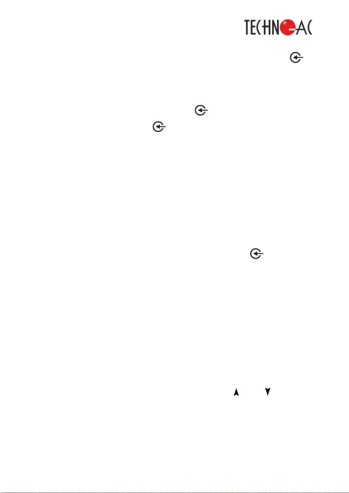
6.7.2 The determination of distance to short circuit between the cable cores
The reflection from irregularity characterizing the cable core short circuit is
expressed in the negative polarity response and is a special case of reduced insulation
resistance. The magnitude of reflected pulse is almost equivalent to the pulse reflected
Cable fault locator TDR-TA3.3T
________________________________________________________________________
________________________________________________________________________
19
from the end of a cable. The reflected pulse in the cursor position 1 of a negative polarity
denotes the short circuit in the cable line. There is no reflected pulse from the end of cable.
Picture 6-2 The short circuit
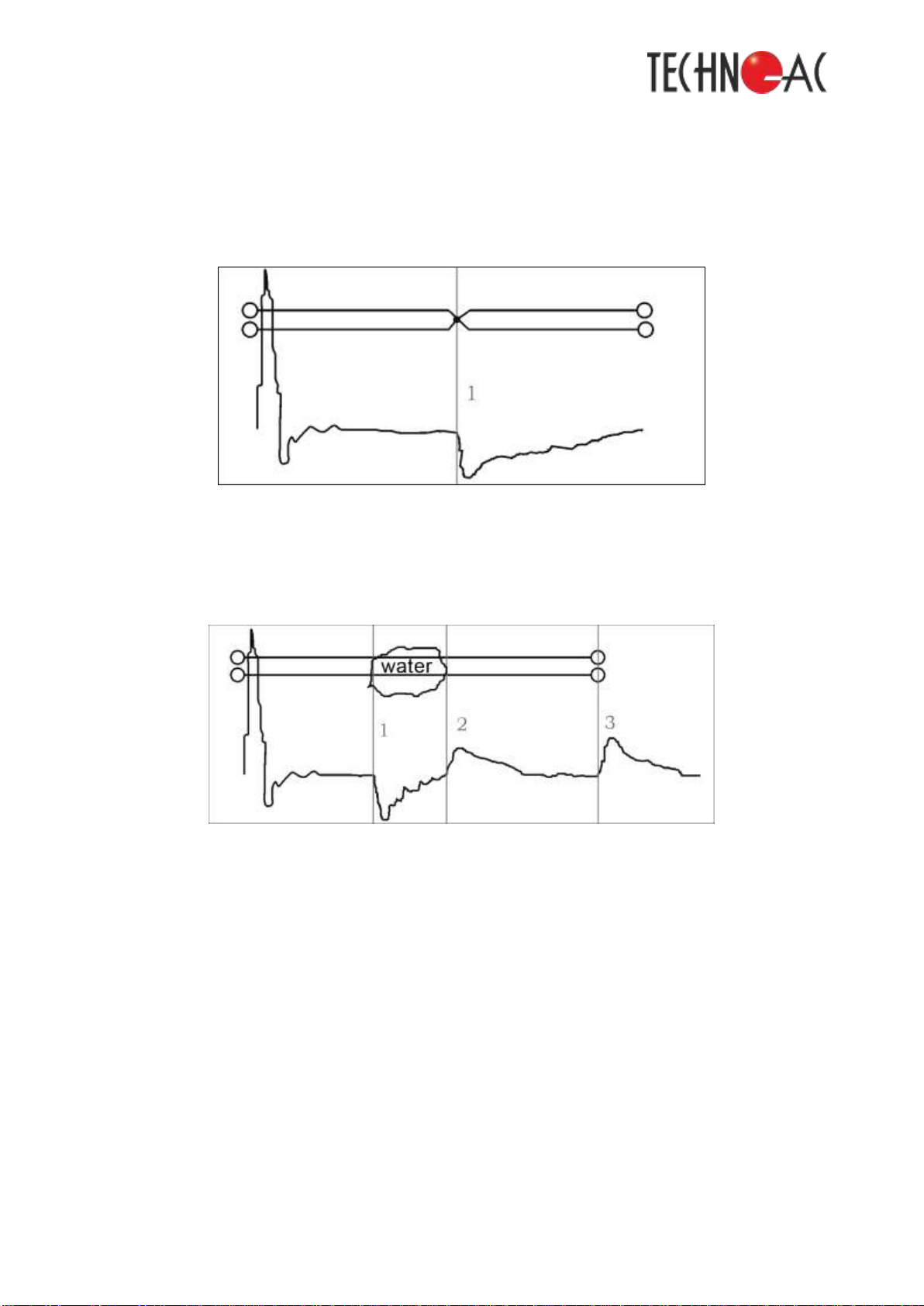
6.7.3 The determination of distance to the “sodden” part of cable
Picture 6-3 The “sodden” part of cable
The irregularity connected with the appearance of moisture in the core of cable
refers to extended irregularity. The “sodden” part of cable is characterized with reduced
resistance and a random value of dielectric permittivity of insulation. To evaluate the length
of a “sodden” part of cable it is required to set the cursor to the beginning of a “sodden”
part and then to set the starting point at the end of cable and to calculate the length of a
dry part of cable. The “sodden” part starts in the cursor position 1 and ends in the cursor
position 2 on the waveform.

Cable fault locator TDR-TA3.3T
________________________________________________________________________
________________________________________________________________________
20
6.7.4 The determination of distance to a parallel tap
The irregularity connected with the cable taps is also extended. By the waveform
view the tap reminds of cable clogging. The difference is that the tap looks like uniform
section. To determine the distance to tap point it is necessary to set the cursor to the
beginning of irregularity. If the tap length is longer that the rest part of the cable, the pulse
reflected from the end of cable might completely disappear. The reflected pulse that by its
shape indicates the availability of a parallel tap in the cable line is to be observed in the
cursor position 2.
Picture 6-4 A parallel tap
6.8 Set of a distance reference point
To set the zero distance on the random point of the waveform it is necessary to:
set the cursor on the random point of the waveform with the buttons «» and«»;
press the button « ». At pressing the button « » the symbol « » at the right
part of the display is being inversively selected;
to cancel press the button « » twice.
6.9 Setting of the measurement window (subrange) offset to the beginning of
measurements
Press the « » button to set the measurement window (subrange) offset to the
beginning of measurements.
Table of contents
Other TECHNO-AC Test Equipment manuals


