VeEX VePAL BX100A Series Guide

BX100A and BX100V Series e-Manual
Please direct all questions to your local VeEX Sales Office, Representative or Distributor or contact VeEX technical support at
www.veexinc.com © Copyright 2010 VeEX Incorporated. All rights reserved.
No part of this user manual may be reproduced, translated into a foreign language or be transmitted electronically without prior
agreement and written consent of VeEX Incorporated as governed by International copyright laws. Information contained in this
manual is provided "as is" and is subject to change without notice. ™Trademarks of VeEX Incorporated have been identified
where applicable, however the absence of such identification does not affect the legal status of any trademark.
BX100A/V e-Manual D07-00-001 Rev E01
Page 1 of 52

Table of Contents
1.0 Product Introduction
1.1 Test Applications
2.0 About this User Manual
3.0 Safety Information
4.0 Basic Operation
4.1 Keypad
4.2 Touch-Screen Display
4.3 Battery
4.4 Connectors and Panels
4.5 LEDs
5.0 Home Menu
5.1 DSL Link Overview
5.2 ATM Overview
5.3 IP Overview
5.4 Pass Through Overview
5.5. Bitstogram Overview
5.6 Digital Multimeter Overview
6.0 DSL Measurement Setup
6.1 ADSL CPE (ATU-R) mode: (ANSI, G.DMT, G.Lite, ADSL2, ADSL2+, Multi
ADSL, Multi G.992.x, Multimode, ADSL2+ Annex M)
6.2 VDSL CPE (VTU-R) mode (VDSL1, VDSL2)
6.3 ADSL CO (ATU-C) mode (ADSL, ADSL2, ADSL2+, ADSL2+ Annex M)
6.4 VDSL CO (VTU-C) mode (VDSL1, VDSL2)
7.0 DSL Measurement Mode
8.0 ATM Measurement Mode
9.0 IP Measurement Mode
BX100A/V e-Manual D07-00-001 Rev E01
Page 2 of 52

10.0 Pass Through Measurement Mode
11.0 Bitstogram
12.0 DR.DSL Loop Diagnostics
13.0 Digital Multi-Meter (DMM)
14.0 Common Functions
14.1 Auto Test
14.2 Settings
14.3 Files
14.4 Help
14.5 Backlight
14.6 Tools
15.0 Warranty and Software
16.0 Product Specifications
17.0 Certification and Declarations
18.0 About VeEX
Go back to top
1.0 Product Introduction
VeEX™ VePAL BX instruments are next generation test solutions to install and maintain xDSL networks delivering triple play
services. All BX products are lightweight, rugged and weather resistant instruments featuring advanced IP test capabilities. The
BX100A models are equipped with a built in modem option to validate ADSL2+/ADSL2/ADSL based networks while the BX100V
unit is equipped with a modem capable of supporting VDSL2 and ADSL2+ networks.
BX100A/V e-Manual D07-00-001 Rev E01
Page 3 of 52

1.1 Test Applications
The diagram below outlines the major test capabilities of the BX100A/V products.
BX100A/V e-Manual D07-00-001 Rev E01
Page 4 of 52

Go back to top
2.0 About this User Manual
Every effort was made to ensure that the information contained in this user manual is accurate. Information is subject to change
without notice and we accept no responsibility for any errors or omissions. In case of discrepancy, the web version takes
precedence over any printed literature.
(c) Copyright 2006-2010 VeEX Inc. All rights reserved. VeEX, VePAL are registered trademarks of VeEX Inc and/or its affiliates in
the the USA and certain other countries. All trademarks or registered trademarks are the property of their respective companies.
BX100A/V e-Manual D07-00-001 Rev E01
Page 5 of 52

No part of this document may be reproduced or transmitted electronically or otherwise without written permission from VeEX Inc.
This device uses software either developed by VeEX Inc or licensed by VeEX Inc from third parties. The software is confidential
and proprietary of VeEX Inc. The software is protected by copyright and contains trade secrets of VeEX Inc or VeEX's licensors.
The purchaser of this device agrees that it has received a license solely to use the software as embedded in the device, and the
purchaser is prohibited from copying, reverse engineering, decompiling, or disassembling the software.
This user manual is suitable for novice, intermediate, and experienced users and is intended to help you successfully use the
features and capabilities of the VePAL BX100A and BX100V analyzers. It is assumed that you have basic computer experience
and skills, and are familiar with DSL and telecommunication concepts, terminology, and safety.
For more technical resources, visit VeEX Inc web site at www.veexinc.com.
If you need assistance or have questions related to the use of this product, call or e-mail our customer care department for
customer support. Before contacting our customer care department, you must have your product serial number ready. Please go to
Basic Operations section for details on locating your unit serial number in the menus or locate the serial number on the back of the
chassis. Please provide this number when contacting VeEX customer service.
Customer Care:
Phone: + 1 408 970 9090
E-mail: [email protected]
Website: www.veexinc.com
Go back to top
3.0 Safety Information
Safety precautions should be observed during all phases of operation of this instrument. The instrument has been designed to
ensure safe operation however please observe all safety markings and instructions. Do not operate the instrument in the presence
of flammable gases or fumes or any other combustible environment. VeEX Inc. assumes no liability for the customer's failure to
comply with safety precautions and requirements.
Go back to top
4.0 Basic Operation
4.1 Keypad
The unit is powered on and off from the red key on the keypad area. In order to turn off the unit, press the Power key for at least 2
seconds. If the unit is not responding, holding the Power key down by more than 10 seconds will force the unit to power down.
The keypad includes the following keys:
BX100A/V e-Manual D07-00-001 Rev E01
Page 6 of 52

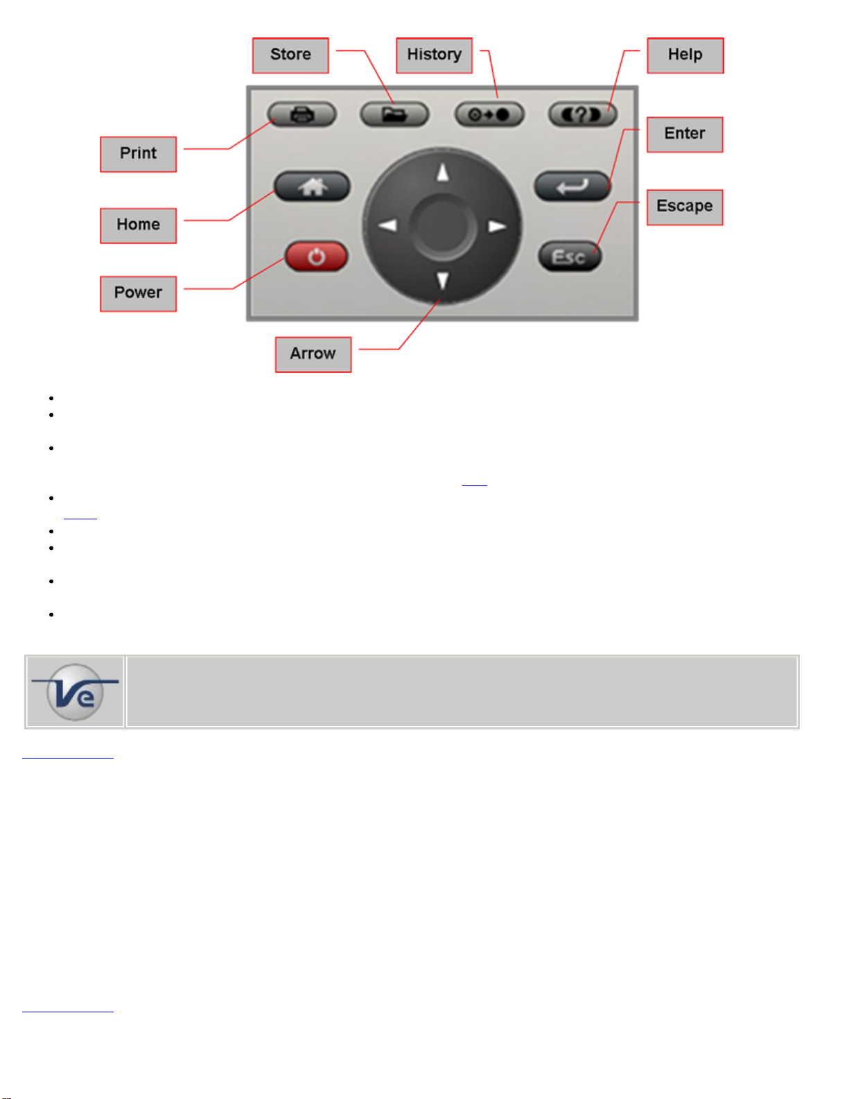
Home key. Bring the unit to its home menu regardless of its location on the user interface.
Print key. Performs a print of the current result or selected stored result. The print function requires a USB printer. For a list
of supported printer please contact VeEX customer service.
Store key. Performs the storage in the memory of the test set of the current results. If the result is running, it will provide a
snap shot at the moment the key is pressed. The store function provides an automatic storage with automatic naming and
time stamping function. To manipulate a stored file, please go to files.
History key. The history key resets any blinking LED due to a history condition. For more details on the LED, please go to
LEDs.
Help key. The help key brings the user to the online help, regardless of the current user interface location of the unit.
Arrow key. The arrow key moves the cursor in any of the four supported directions (left, right, up, down). The arrow key
works in conjunction with the Enter and Escape keys.
Enter key. The enter key provides an enter sequence to the user interface. It is used in non touch screen operation mode to
enter menus and functions.
Escape key. The escape key provides an escape sequence to the user interface. It is used in non touch screen operation
mode to escape menus and functions.
Note: Standby Mode
By pressing Home and Help buttons simultaneously, the tester switches to a sleep mode which helps to
preserve battery life and makes fast boot up time at the measurement site or location possible.
To exit the sleep mode, press Home and Help simultaneously again.
Go back to top
4.2 Touch-Screen Display
The LCD supports touch-screen operations. In order to use the unit in touch-screen mode, open the transparent door covering the
screen. Then take out the stylus available on the top door i.e. door protecting the connector panel. Keep the LCD cover closed
when using the unit on non touch-screen mode, and use the arrow, enter, and escape keys. The location of the cursor on the
screen is indicated by a focus state. The focus state varies depending on the function or section of the test set. Please observe the
following precautions;
- Never use excessive pressure on the touch-screen as this may damage its functionality
- Never use sharp objects such as a pen, screwdriver etc. as this may damage the surface
- Clean the surface of the touch screen using a soft cloth and mild detergent only. Do not use alcohol.
Go back to top
4.3 Battery
BX100A/V e-Manual D07-00-001 Rev E01
Page 7 of 52

The VPAL is equipped with an intelligent Lilon rechargeable battery pack which is located in the rear of the unit. The battery will be
partially charged upon delivery so it is recommended to charge the battery fully before use. It is recommended to charge the battery
at room temperature to preserve its life and to obtain maximum charge. The battery can be removed during operation provided the
unit is connected to the AC Main using the supplied AC adapter. Removing the battery, when not connected to the AC Main will
cause the unit to shutdown. Remove the rubber cover on the left side to connect the AC Main adapter to the unit.
Go back to top
4.4 Connectors and Panels
Test Ports :
To access the test connectors, please open the top cover.
DSL test port:
One RJ11 (BX100V) or one RJ45 (BX100A) connector is located at the top of the unit. Connect the unit to the network
using one of the cables supplied with the instrument.
Note: Maximum Voltage input is 100VAC, 140VDC
Digital Multimeter test port (option for BX100A models only)
The Digital Multi-Meter (DMM) measures AC and DC voltage, current and resistance. Connect to the network using the test
cables supplied with the instrument.
POTS test port: (option for BX100A models only)
Utility Ports:
To access the utility ports, remove the protective rubber cover on the right hand side of the unit to expose the connectors;
USB 2.0 Client port: To connect USB memory drives, WiFi or VoIP adaptors. These accessories are shown below.
BX100A/V e-Manual D07-00-001 Rev E01
Page 8 of 52

USB 2.0 Host port: To connect USB printer (future firmware release)
RJ45, 10/100Base-T port: To connect to an Ethernet network. Applications include;
Transfer measurement results and test profiles between the instrument and a computer using ReVeal BX software
Upload/download channel tables between the instrument and a computer using ReVeal BX software
Upgrade the instrument software using ReVeal BX software
Remote control of the instrument using ReVeal BX software (optional)
Go back to top
4.5 LEDs
The BX100A series are equipped with four LEDs providing the following functions;
The Power LED indicates the power state of the unit. The LED is off when the unit is powered off. The LED is green
when the unit is powered on. The LED is orange when the unit is connected to the AC Main and powered off.
The ALM/ERR LED is linked to the alarms and errors. The LED is solid red when there is an alarm or error condition. The
LED is flashing red to indicate an error or alarm that has occurred but is no longer present. This is called the history
function. In order to reset the history condition on any LED press the function key on the rubber keyboard (O -> O).
The FRAME LED indicates synchronization aspects of the DSL signal. The LED is green when showtime or link-up is
achieved. The LED is red while the unit is training or the expected DSL signal can not be detected.
The SIGNAL LED is related to the physical status of the built-in DSL Modem. A solid green LED indicates the modem has
synchronized with the DSLAM and showtime is achieved.
The BX100V is equipped with three LEDs providing the following functions;
The Power LED indicates the power state of the unit. The LED is off when the unit is powered off. The LED is green
when the unit is powered on. The LED is orange when the unit is connected to the AC Main and powered off.
The SIGNAL LED is related to the physical status of the built-in DSL Modem. A solid green LED indicates the modem has
synchronized with the DSLAM and showtime is achieved.
The ALM/ERR LED is linked to the alarms and errors. The LED is solid red when there is an alarm or error condition. The
LED is flashing red to indicate an error or alarm that has occurred but is no longer present. This is called the history
function. In order to reset the history condition on any LED press the function key on the rubber keyboard (O -> O).
Go back to top
BX100A/V e-Manual D07-00-001 Rev E01
Page 9 of 52

5.0 Home Menu
This menu can be reached at anytime during operation by pressing the home key, accessible on the rubber keypad.
BX100A Home Menu BX100V Home Menu (CPE mode)
The upper part of the menu (DSL link, ATM, IP, Pass through, Bitstogram etc) contains items specific to the test application of the
handheld test set, while the lower part of the menu contains items common to all VeEX VePAL handheld test sets.
Some test capabilities may be specific to a certain product while other features may require the purchase of a software option in
order to be displayed or be enabled.
5.1 DSL Link
ADSL and VDSL technology re-uses the copper pair between the exchange or street cabinet and the customer premises. The
usable bandwidth is extended from 4kHz to 2.2MHz in the case of ADSL2+ and 4kHz to 30MHz in the case of VDSL2. Extended
bandwidths make the copper pair far more susceptible to faults, impairments and other degradation thus impacting the BER.
Testing at this layer not only provides information about the copper's performance, but connection to the DSLAM or customer's
modem can also be assessed.
The BX100A/V models offer the following test functions depending on model purchased;
Emulate customer modem (ATU-R) to prove that synchronization or link up with DSLAM is possible.
Emulate DSLAM (ATU-C) to prove that synchronization or link up with a customer modem (ATU-R) is possible (BX100V
with xTU-C options only)
Provide link performance statistics - Measure downstream bit rate, upstream bit rate, max bit rate, relative capacity, noise
margin, transmit power and attenuation.
Display bits per tone in both graphical and table format.
Display SNR per tone in both graphical and table format.
Counts FEC, HEC and CRC error frames and detects and indicates Loss of signal, Loss of cell declineation
Modem emulation - replace the customer modem and measure data performance with live customer traffic in Pass Through
mode.
Go back to top
5.2 ATM Function
The ATM link proves the communication path from the customer's equipment through the Service Provider's backbone network.
Testing the ATM layer verifies correct equipment setup.
BX100A/V e-Manual D07-00-001 Rev E01
Page 10 of 52

OAM F5 loopback support.
VPI/VCI scan returns list of available VPI/VCI.
ATM PING (end to end or segmented).
ATM F4 and F5 OAM cells to check connectivity between various network points
Note: ATM versus IP DSLAMs
ATM DSLAM: When ADSL services first began, ATM was the main high-speed data backbone transport
used in telecommunications networks. As a result, DSLAMs with an ATM uplink or backplane were
developed to enable the ADSL link to connect seamlessly into the whole ATM network. The 'last mile' ATM
link over the ADSL line was merely an extended part of the telco’s ATM network.
IP DSLAM: More recently, Ethernet bandwidth capabilities have increased significantly and it is becoming a
cheaper and more popular transport protocol choice for Metro Area Networks. In installations where
subscribers are using DSL to access a Metro Area Network, it makes sense for the DSLAMs to have
Ethernet uplink ports. DSLAMs with Ethernet uplink ports are known as IP DSLAMS. The market is rapidly
moving towards IP DSLAMs because they are cheaper to implement, scale better and are easier to manage
than ATM DSLAMs.
Go back to top
5.3 IP Function
An IP test will verify if the whole DSL system is configured properly and connected to the Internet. Depending on the IP options
purchased, the following tests are possible;
Ping Test: PING is a popular computer network tool used to test whether a particular host is reachable across an IP
network. Sending an “echo request” or ICMP (Internet Control Message Protocol) to the target host and listening for “echo
response” replies. PING estimates the round-trip time, in milliseconds, and records any packet loss. The destination address
can be in IP address or URL format.
Trace Route: To find the route to the destination IP or URL. Often used to identify routing problems and unreachable
destinations. All the remote IP addresses and their response times are displayed indicating possible network congestion
points.
FTP Test: Using the File Transfer Protocol, verify the actual throughput of upstream or downstream data rate by sending
or receiving files with known size
Web Test/ Web Browser: To verify internet is properly connected by the service point. Allows user to perform work force
management related tasks.
VoIP: Refer to Common Features manual
IPTV: Refer to Common Features manual
Go back to top
5.4 Pass Through Function
In Pass Through mode, the BX100A/V emulates a customer's modem by synchronizing with the DSLAM, making data analysis
(Ping, Traceroute, HTTP/FTP), Web surfing via a PC, IPTV STB emulation, and VoIP analysis possible. The unit is connected to
the DSL line via the RJ11 or RJ45 interface and to a PC via the Ethernet 10/100Base-T port. Used in this "transparent" mode, this
test helps to verify;
The customer’s modem or router is working correctly
The IPTV quality of experience (QOE) by monitoring joins/leave request, zapping time, jitter and delay
Sufficient bandwidth is available to deliver Triple-Play services
VoIP call flow, jitter, and delay
Go back to top
5.5 Bitstogram - Option for all BX100A/V Models
The Bitstogram feature measures the bits per tone distribution the modem transmits to deliver the provisioned data rate. The
number of bits assigned per tone is displayed in both graphic and tabular formats. The Bitstogram feature is useful to troubleshoot
interference problems, to monitor bit swapping and Seamless Rate Adaptation (SRA) occurring over a period of time.
BX100A/V e-Manual D07-00-001 Rev E01
Page 11 of 52

Go back to top
5.6 Digital Multi-Meter (DMM) - Option for BX100A Models Only
DMM measurements help verify that the copper pair meets specified requirements for DSL service. These tests are normally
conducted during the pre qualification phase or on problematic service loops.
Go back to top
6.0 DSL Measurement Setup
The Setup menu can be reached at anytime during operation by pressing the Home key, accessible on the rubber keyboard.
BX100A ADSL Setup Menu BX100V ADSL Setup Menu - Annex A
6.1 ADSL CPE (ATU-R) Setup:
The following ADSL test functions are available under the Mode tab on the BX100A and BX100V models;
ANSI: Enables ANSI mode.
Defined by the American National Standards Institute (ANSI) Telecommunications Committee, T1.413 was the first standardized
ADSL specification. The underlying modulation is Discrete Multi-Tone (DMT) line code which divides the bandwidth of the standard
two wire copper wire used in the PSTN into 256 separate 4.3125 kHz wide bins called sub-carriers. Even though each of these 254
sub-carriers or tones can support a modulation of up to 15 bits, the maximum achievable downstream data rate is actually 8.128
Mbit/s due to error checking and related overhead data. In the upstream direction, a maximum of 30 sub-carriers is used, each
tone being modulated with up to 15 bits providing a maximum theoretical throughput of just over 1.5 Mbit/s.
Go back to top
DMT: Enables DMT mode.
Also referred to as ITU G.992.1, the standard expands the usable bandwidth of existing copper telephone lines to rates up to 12
Mbit/s downstream and 1.3 Mbit/s upstream. Discrete Multi-Tone (DMT) mode, divides the ADSL signal into 255 carriers (bins)
spaced in multiples of 4.3125 kHz. The DMT spectrum has 224 downstream frequency bins and up to 31 upstream bins.
In Annex A systems where Voice (POTS) is used on the same line, the frequency spectrum can be outlined as follows:
0-4 kHz is allocated to Voice traffic
4-25 kHz is an unused guard band
25-138 kHz is for Upstream data
138-1107 kHz is for Downstream data (ADSL)
BX100A/V e-Manual D07-00-001 Rev E01
Page 12 of 52

138-2208 kHz is for Downstream data (ADSL2+)
ADSL2+ Frequency Plans
Go back to top
G.Lite: Enables G.Lite mode.
A lower data rate version of G.DMT and T1.413 also known as Splitterless ADSL i.e. it uses the same DMT modulation scheme but
eliminates the POTS splitter at the customer premises. As a result, the ADSL signal is carried over all of the house wiring which
results in lower available bandwidth due to greater noise impairments. Initially deployed in 1999 to reduce truck rolls which were
needed to install the splitter at the customer premises.
Go back to top
ADSL2: Enables ADSL2 mode.
Also known as ITU-T G.992.3, the standard extends basic ADSL data rates to 12 Mbit/s downstream and 3.5 Mbit/s upstream
however actual speeds are dependent on line quality - the most significant factor being loop length.
ADSL2+: Enables ADSL2+ mode.
Also known as ITU-T G.992.5, the standard extends the capability of basic ADSL by doubling the number of downstream tones
providing data rates as high as 24 Mbit/s downstream and 1 Mbit/s upstream depending on loop length. ADSL2+ can also be used
to reduce crosstalk because it provides the capability to use only tones between 1.1 MHz and 2.2 MHz thus masking the
downstream frequencies below 1.1 MHz and associated interference - this is also referred to as Spectral Masking.
BX100A/V e-Manual D07-00-001 Rev E01
Page 13 of 52

ADSL2+ Frequency Spectrum
Go back to top
Multi ADSL: Enables Multi ADSL mode.
The test set searches for one the signal types below and will try to synchronize in order of priority;
G.DMT ADSL signal
ANSI T1.413 ADSL signal
G.Lite ADSL signal
Multi G.992.x mode: Enables Multi G.992.x mode.
The test set searches for one the signal types below and will try to synchronize in order of priority;
G.992.5 ADSL2+ signal
G.992.3 ADSL2 signal
G.992.1 ADSL (DMT) signal
Multimode: Enables Multimode mode.
The test set searches for one the signal types below and will try to synchronize in order of priority;
G.992.5 ADSL2+ signal
G.992.3 ADSL2 signal
G.992.1 ADSL (DMT) signal
G.DMT ADSL signal
ANSI T1.413 ADSL signal
G.Lite ADSL signal
ADSL/2+ Annex B: Enables Annex B mode. (Screen layout differs slightly on BX100A and BX100V models)
In Annex B systems, where voice (ISDN) is used on the same line, the frequency spectrum can be outlined as follows:
0-80 kHz is allocated to ISDN service (160kbps full duplex and 2B1Q line coding). For 4B3T line coding, frequency
allocation is slightly different.
80-120 kHz is typically a guard band
120-276 kHz is for Upstream data
276-1107 kHz is for Downstream data (ADSL)
276-2208 kHz is for Downstream data (ADSL2+)
BX100V ADSL Setup Menu - Annex B BX100V ADSL Setup Menu - Annex M
ADSL2 Annex M: Enables ADSL2 Annex M mode.
BX100A/V e-Manual D07-00-001 Rev E01
Page 14 of 52

Also known as ITU G.992.5 Annex M, the standard extends the capability of basic ADSL2 by doubling the number of upstream
bits. Data rates can be as high as 24 Mbit/s downstream and 3.5 Mbit/s upstream depending on the distance from the DSLAM to
the customer premises. The main difference between this and ITU G.992.5 (ADSL2+) specification is that the
upstream/downstream frequency split has been shifted from 138kHz up to 276kHz, allowing upstream bandwidth to be increased
from 1 Mbit/s to 3.5 Mbit/s, with a corresponding decrease in downstream bandwidth.
Go back to top
ADSL Standards Summary
Go back to top
6.2 VDSL VTU-R (CPE) Mode
The BX100V offers the following VDSL/2 modes;
CPE (VTU-R) mode to emulate a VDSL/2 modem
BX100V VDSL Menu - CPE mode
BX100A/V e-Manual D07-00-001 Rev E01
Page 15 of 52

VDSL mode: Enables Infineon/Aware mode.
Efforts to standardize VDSL got underway in 1995 with the ITU, ETSI and ANSI (T1E1.4) organizations each conducting
simultaneous projects. The adoption/ratification of the standard was hampered by the choice of two competing line-code
technologies i.e. using quadrature amplitude modulation (QAM); and discrete Multitone (DMT). As a result, proprietary
implementations of VDSL-QAM and VDSL-DMT were developed and deployed in limited volumes in a few markets. VDSL1
supports a bandwidth of up to 12MHz. The physical reach of VDSL1 is limited to around 1500m on 0.4mm cable.
VDSL2 mode: Enables Infineon/Aware VDSL2 mode.
Frequency configuration options of 8.5 MHz, 12 MHz, 17.7 MHz and 30 MHz are set automatically depending on DSLAM settings.
Note: VDSL2 backgrounder
Based on inputs from the ANSI and ETSI standards, ITU drafted the VDSL2 standard (G.993.2) in 2004 and
it was approved in May 2005. The underlying modulation in the VDSL2 standard is discrete Multitone (DMT)
and is based on both the VDSL1-DMT and ADSL2/ADSL2+ recommendations. As a result, it is spectrally
compatible with existing services and enables very important multimode operability with ADSL/2/+.
VDSL2 is designed to support a wide deployment of Triple Play services and permits the transmission of
asymmetric and symmetric data rates up to 200 Mbit/s. The bandwidth can be extended to 30MHz however
VDSL2 uses the same band plans below 12MHz to be spectrally compatible with VDSL1. The physical reach
of VDSL2 can be extended to around 2400m on 0.4mm cable.
VDSL CNXT: Enables Conexant VDSL mode.
Supports and improves interoperability with Conexant chipset based VDSL1 DSLAMs using DMT modulation.
VDSL2 CNXT: Enables Conexant VDSL2 mode.
Supports Conexant based VDSL2 DSLAMs using DMT modulation. Bandplan configuration options of 8.5 MHz, 12 MHz, 17.7 MHz
and 30 MHz are set automatically depending on DSLAM and operator settings.
VDSL IKO: Enables Ikanos VDSL mode.
Supports Ikanos based VDSL1 DSLAMs using DMT modulation.
VDSL2 IKO: Enables Ikanos VDSL mode.
Supports Ikanos chipset based VDSL2 DSLAMs using DMT modulation. Bandplan configuration options of 8.5 MHz, 12 MHz, 17.7
MHz and 30 MHz are set automatically depending on DSLAM and operator settings.
Note: VDSL interoperability:
Initial VDSL standards were never fully adopted by the market due to disagreements during the
standardization phase regarding the modulation scheme (DTM or QAM) and packet technology (ATM or
Ethernet) to be used. Even though interoperability testing of VDSL2 is a top priority of chipset and equipment
vendors, experience from working with ADSL indicates that it might take a a few years to reach full
interoperability.
BX100A/V e-Manual D07-00-001 Rev E01
Page 16 of 52

The first step in the process is to gain layer-1 interoperability between chipset vendors. Once that is
achieved, system vendors can perform additional tests between CPE and DSLAMs. The DSL Forum is
defining the framework for the VDSL2 tests in several important documents that will guide the industry
forward.
For the reasons stated, above, the BX100V is equipped with different vendor profiles to deal with potential
compatibility issues and customer deployments.
Go back to top
ATM mode: Enables Asynchronous Transfer Mode (ATM) encapsulation of Ethernet frames.
PTM mode: Enables Packet Transfer Mode (PTM) encapsulation of Ethernet frames.
Note:
Asynchronous Transfer Mode (ATM) versus Packet Transfer Mode (PTM)
VDSL2 specifies a Packet Transfer Mode – Transmission Convergence (PTM-TC) function that is based
on the Ethernet in the First Mile (EFM) IEEE 802.3ah standard. The PTM-TC specified in VDSL2
makes provision for Preemption and Short Packet Support.
Preemption improves traffic management by pausing the transmission of a low-priority packet when a
high-priority packet needs to be transmitted. Thus high-priority packets (e.g. voice) experience a
minimum amount of packet insertion delay.
Short Packet Support enables a VDSL2 system to transport packets that contain less than 64 bytes.
While IEEE802.3 was designed exclusively for the transport of Ethernet packets greater than 64 bytes,
VDSL2 transports any packet type, including IP packets which are often less than 64 bytes.
So when introducing VDSL2, there will be a strong tendency from operators to drop ATM in the first
mile, and to replace it with Ethernet (64/65 encapsulation).
Go back to top
BX100A/V e-Manual D07-00-001 Rev E01
Page 17 of 52

6.3 / 6.4 VDSL/ADSL CO Setup Mode
The BX100V offers various setup modes. In Page #1 of 4 the following ATU-C or VTU-C configurations are possible;
CO (ATU-C) mode to emulate a ADSL/2/2+ DSLAM
Annex A ADSL/POTS
Annex B ADSL/ISDN
Annex M
CO (VTU-C) mode to emulate a VDSL/2 DSLAM
BX100V CO Setup Menu
VDSL mode: Emulates Infineon/Aware VDSL1 based DSLAMs using DMT modulation.
VDSL2 mode: Emulates Infineon/Aware based VDSL2 DSLAMs using DMT modulation.
VDSL CNXT: Emulates Conexant based VDSL1 DSLAMs using DMT modulation.
VDSL2 CNXT: Emulates Conexant based VDSL2 DSLAMs using DMT modulation.
VDSL IKO: Emulates Ikanos based VDSL1 DSLAMs using DMT modulation.
VDSL2 IKO: Emulates Ikanos based VDSL2 DSLAMs using DMT modulation.
ATM mode: Enables Asynchronous Transfer Mode (ATM) encapsulation of Ethernet frames.
PTM mode: Enables Packet Transfer Mode (PTM) encapsulation of Ethernet frames.
Go back to top
VDSL/ADSL CO Mode - Upstream and Downstream setup:
In Page # 2 of 4, the Upstream parameters can be configured.
In Page # 3 of 4, the Downstream parameters can be configured.
BX100V CO Setup - Upstream BX100V CO Setup - Downstream
BX100A/V e-Manual D07-00-001 Rev E01
Page 18 of 52

Upstream and Downstream - The following parameters are adjustable;
Data rate (maximum)
Data rate (minimum)
SNR target: Signal to Noise Ratio
SNR (maximum)
SNR (minimum)
INP (minimum) - Impulse Noise Protection value
BX100V CO Setup - INP Editor
Note: Impulse Noise Protection (INP):
Electrical appliances and installations at customer premises often generate short bursts of noise of relatively
high amplitude. These bursts, called impulse noise, are electromagnetically coupled into the digital subscriber
line, degrading performance and in some cases disrupting service. The ADSL2/+ standard introduced a
parameter called Impulse Noise Protection (INP), that allows operators to select the maximum impulse length
that the DSL system can correct.
BX100A/V e-Manual D07-00-001 Rev E01
Page 19 of 52

VDSL2 uses the same parameter and when implemented, an INP value between 2 and 16 can correct errors
from noise impulses ranging from 250µs to 3.75ms in length.
INP is a key feature in most IPTV video deployments and enables better Video QOS by minimizing the
effects of Impulse Noise.
The INP value for the interleaved channel can be set by the user and is expressed in symbols. For example,
an INP value of 1 means that 1 symbol can be corrected i.e. a burst of noise for 1 symbol duration can be
corrected without errors. One symbol equals 250 µs, therefore an INP of 1 correlates to a correction time of
250 µs.
The Impulse Noise Protection (INP) or interleave depth is defined by the S and D parameters where;
S is the Interleave DMT symbols per FEC code word (1,2,4,8,16)
D is the Interleave depth (1,2,4,8,16,32,64)
Interleave delay can vary from 4.25 to 263.75 msec
The graphic below shows various Impulse Noise Sources
Go back to top
VDSL/ADSL CO Mode - Bandplan Setup:
In Page # 4 of 4, Bandplans can be selected (available in VDSL2 mode only)
BX100V CO Setup - Bandplans BX100V CO setup Bandplan selection
BX100A/V e-Manual D07-00-001 Rev E01
Page 20 of 52
This manual suits for next models
1
Table of contents
Other VeEX Test Equipment manuals

VeEX
VeEX VePAL TX300 User manual

VeEX
VeEX RXT-6200 User manual

VeEX
VeEX VePAL TX300M User manual

VeEX
VeEX WiFi Air Expert Series User manual

VeEX
VeEX Fiber Scope Inspector User manual

VeEX
VeEX VePAL TX300 User manual

VeEX
VeEX MPX100 User manual

VeEX
VeEX MTTplus-420 User manual

VeEX
VeEX MTT-14B User manual

VeEX
VeEX VePAL TX300 User manual