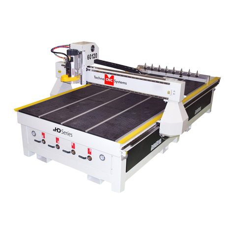
Techno Premium Series Manual

Techno
Inc.
HTT03170704
Premium Class Setup Instructions
Phone: 516-328-3970 · Web: www.technocnc.com
ADDITIONAL DOCUMENTATION
Can be found in the “More Manuals”
folder on your TECHNO CD-ROM.
INSTALLATION & SETUP TABLE OF CONTENTS
I. Machine Identifications
II. How To Use the Vacuum Table
III. Scale Factor Setup
APPENDICES
A. Techno Electronics
B. Colleting Guidelines
C. Machine Maintenance
CUSTOMER SUPPORT WEBSITE
http://support.technocnc.com/
Visit this site for software updates
and the Tech-Support Wizard.
This Wizard is password protected
for our customers.
Username: technocnc
Password: multiaxis

Techno
Inc.
HTT03170704
2
Premium Class Setup Instructions
Phone: 516-328-3970 · Web: www.technocnc.com
Continue to next page …
HAVE A LICENSED ELECTRICIAN PERFORM ALL ELECTRICAL
CONNECTIONS BASED ON YOUR LOCAL CODES
Leveling Bolts / Feet
Airline Connection /
Leveling Feet Thru Hole
1- The toolchanger models must be connected to
an air supply from a clean, dry, non-fluctuating
source (90-110 psi). Please set the regulator to an
appropriate psi level. Machine regulator should
be set to 90 psi.
Screw the leveling bolts in the threaded holes.
Adjust them to level the machine.
Remove the packing material from around the computer. Please keep the computer
documentation in the CNC Control Unit Computer Cabinet. The WARRANTY paperwork
is part of this package.
1
Incoming AC Power
Connect the incoming AC
power to the machine here
Note: The indicated voltage on
the box. Turn power OFF when
the machine is being serviced.
CNC Control Unit
CNC Control Unit Panel
Emergency Stop
Button (E-Stop)
Vacuum Pump
1 Switch
Vacuum Pump 2 Switch
(If Present)
Start / Stop
Switches
Brake Switch
Spindle Control
Panel / Display
(Factory Preset)
CNC Control Unit Wires
There are two wires coming
from the rear of the CNC
Control unit. These must be
plugged into an outlet with
the voltage indicated on the
label. Please note the specified
Voltage label.
I. MACHINE IDENTIFICATIONS
IMPORTANT: KEEP YOUR TECHNO CD-ROM. IT CONTAINS ADDITIONAL DOCUMENTATION.
NOTE ¹: Voltage on the main
power line must be measured
and the correct tap on the input
transformer must be selected.
NOTE ²: Clean, dry air must be
used otherwise damage to the
spindle and air solenoids will
result. THIS IS NOT COVERED
UNDER WARRANTY.
It is strongly recommended
that all 220 and 440VAC
connections be connected
through a power disconnect
switch (example seen left) for
use with either CNC Router
spindle and/or vacuum pump
setup. This switch is required
for safety and to meet National
Electrical Codes. A licensed
electrician should perform this
installation.
Power Disconnect Switch
(not included with Purchase)

Techno
Inc.
HTT03170704
3
Premium Class Setup Instructions
Phone: 516-328-3970 · Web: www.technocnc.com
Continue to next page …
Vacuum Pump Motor
Starter Box & Connector
II. HOW TO USE THE VACUUM TABLE
The motor has been wired to the Motor
Starter. The incoming voltage must be wired
to the Motor Starter Box.
NOTE: Voltage is specified on the box
Vacuum Pump w/ Motor Starter
The signal connector needs
to be connected to its mating
connector (shown left).
Pump/Blower Cable
You will need to connect the
AC power (220 or 440 VAC)
as specified on the unit to
the Motor Starter.
Connect one end of the 2”
diameter vacuum hose to
the manifold fitting …
… and connect other end of the
vacuum hose to the Vacuum
Pump filter.
Vacuum Hose Fittings …
Tool Changer Rack (if applicable)
Vacuum Shroud
Place the toolholders here on the tool
holder rack. Please note the collets
and the collet wrenches are supplied
with the unit. Refer to manual on how
to teach tool locations.
Note¹: Make sure the distance
between Tool Holders is greater than
the length of the vacuum shroud/dust
collector.
WARNING: Direction of Rotation is critical. Briefly start motion and check rotation (arrow
on casing). Exchange phases if rotation is incorrect. IF YOU RUN THE PUMP/BLOWER
CONTINUOUSLY IN THE WRONG DIRECTION THE VANES WILL BE DAMAGED.
The dust collector shroud is
mounted through the block next to
the spindle and the dust collector
hose should be attached to the
fitting supplied with the shroud.

Techno
Inc.
HTT03170704
4
Premium Class Setup Instructions
Phone: 516-328-3970 · Web: www.technocnc.com
Continue to next page …
TO REORDER VACUUM SUPPLIES:
Call Techno Today at: 516-328-3970
ITEM PART NUMBER
Rubber Plugs H91X30-PL006-001
Foam Rubber Gasketing HX4892-W0002
II. HOW TO USE THE VACUUM TABLE (CONT.)
Vacuum Hold-Down - 1
The Techno Vacuum Table is very effective in
“holding down” parts to be routed. For this method
to work and work well, simple procedures need
to be followed. First, you need to define the
area where your workpiece will be positioned on
the vacuum table. Second, using the red rubber
plugs, you need to plug-up and close-off all of the
area outside your defined work area. Fill in ALL
the vacuum grid holes outside your defined work
area with the plugs and leave the holes within your
work area open. Next, use the black foam rubber
gasketing to section/wall-off your work area. The
idea is to create an area of concentrated vacuum,
which will generate the greatest amount of vacuum
“hold-down.”
Vacuum Hold-Down - 2
After you have defined your workpiece
area and closed off all the vacuum
outside of that area, there is another
option to greater your vacuum: the
vacuum control valves. Each valve
controls the flow of vacuum to two rows
of extrusions. Turn ON (valve vertical)
the valves that pertain to your work area
and turn OFF (valve horizontal) the ones
outside of that area. This will concentrate
all the vacuum “hold-down” capacity to
your defined work area.
NOTE: You do not need to plug vacuum
holes in a section that has the valve
turned OFF.
WARNING: Proper care should be taken to make sure that objects held down with the vacuum table
are secure. There is a danger that objects held down with the vacuum can become loose and could be
thrown by the action of the cutting tool. Proper safety precautions against flying debris must be taken.
Safety glasses must be worn when the vacuum table is being used.
Important Gasketing Installation Notes:
1) DO NOT STRETCH the gasket material while
inserting it into the gasket slots. This will
produce tears in the gasket material which
causes leaks leading to the loss of vacuum
and unsecure pieces flying off of the vacuum
table.
2) When joining two separate pieces of gasket
material, make sure to push them together
so the two pieces forma tight seal.

Techno
Inc.
Phone: 516-328-3970 · Web: www.technocnc.com
5
HTT02740704 Scale Factor Interface Setup
Continue to next page …
IF THE VALUES ARE NOT WRITTEN ON THE FRONT LEG OF
YOUR TECHNO CNC ROUTER THEN THE INTERFACE DEFAULT
VALUES SHOULD APPLY.
III. SCALE FACTOR SETUP:
STEP 1: Start Techno CNC Interface.
STEP 2: From the Main Menu click on
the Setup button. See SCREEN
CAPTURE 1.
STEP 3: Click on System in the Setup
screen’s menu list. See SCREEN
CAPTURE 2.
NOTE¹: The Setup/System screen will
appear.
STEP 4: Input the numbers printed
on the Scale Factor Sticker
located on the front leg of the
machine.
NOTE²: See the circled section in
SCREEN CAPTURE 2. Make sure
to type the numbers exactly
how they appear on the sticker
including any negative values
(i.e. -20320).
STEP 5: Click the OK button in the
Setup/System screen to save
the changes made.
SCREEN CAPTURE 1
SCREEN CAPTURE 2

Techno
Inc.
HTT03170704
6
Premium Class Setup Instructions
Phone: 516-328-3970 · Web: www.technocnc.com
Continue to next page …
APPENDIX A
PCI CARDS CONTROL BOXES
NOTE: THE MP ELECTRONICS MAY SHIP WITH GANTRY III SYSTEMS, CHECK ROUTER SPEC. SHEET FOR DETAILS.
PCI Interface Card The PCI Controller Card
This card works with:
· LP(LC) Electronics
· CNC Lathes
· Servo DaVinci
· Gantry III Machines
LP (or “LC) Electronics are stan-
dard on the Servo Lathes (Metal
& Wood), Servo DaVinci’s and
the standard LC Machines (NOT
THE SPEED UPGRADE LC’s!)
They can also be used on Gantry
III Tabletop Series machines and
as a stand alone product.
MP Electronics are sometimes
referred to as Servo Box 2
(H26T56-SRVBOX2).
LP (LC) ELECTRONICS MP ELECTRONICS
HP ELECTRONICS
CNC CONTROL TOWER
The HP Electronics Box com-
ponents are located within the
Techno CNC Control Tower,
which comes standard with a
Premium Class machine and as
an upgrade for the RG Series
machines.
WARNING: Make sure to match the correct PCI Card with the corresponding Techno Electronics.
Mixing the Interface Card with the MP/HP Electronics, or using the Controller Card with the LP Electronics
may cause damage to the Electronics, the PCI Card and your computer.
9.25’’
5.75’’
This card works with:
· MP Electronics
· HP Electronics:
RG+ Servo Box 3
· Premium Class
Electronics
· LC Speed Upgrades
· RG Machines
· Some Gantry III
Machines
HP Electronics are referred to as
Servo Box 3 or RG+ Servo Box
3 (H26T56-SRVBOX3HR).

Techno
Inc.
HTT03170704
7
Premium Class Setup Instructions
Phone: 516-328-3970 · Web: www.technocnc.com
Continue to next page …
APPENDIX B

Techno
Inc.
HTT03170704
8
Premium Class Setup Instructions
Phone: 516-328-3970 · Web: www.technocnc.com
Continue to next page …
Y-Axis – THK Products
Grease: Lithium-based grease (JIS NO. 2) or Urea-based Grease (JIS No.
2), such as AFB Grease (THK), Alvania Grease No. 2 (Shell), Daphne Eponex
Grease No. 2 (Idemitsu Kosan) or equivalent.
Oil: Sliding surface oil or turbine oil (ISOVG32-68), such as Super Multi 32
to 68 (Idemitsu Kosan), Vactra No. 2S (Mobile), DT Oil (Mobile), Tonner Oil
(Shell) or equivalent.
TABLE 1
THK
BALLSCREW RAIL CARRIAGE
GREASE
OIL
√
√
√
√
√
AVAILABLE ACCESSORIES
TECHNO LUBE KIT PART NO.: H90Z00-LUBEKIT3 PRICE: $75.00
THK LUBE KIT PART NO.: H90Z00-LUBEKIT4 PRICE: $105.00
LUBRICATION SPECS FOR PREMIUM CLASS MACHINES
Note: On some items you can use either the grease or oil.
APPENDIX C

Techno
Inc.
HTT03170704
9
Premium Class Setup Instructions
Phone: 516-328-3970 · Web: www.technocnc.com
Continue to next page …
PREMIUM CLASS MACHINE MAINTENANCE
For regular work loads, machine maintenance is
required at least once a month. The machine should
also be lubricated once it is received.
Warning: Before inserting any object into the
machine, press the E-stop button.
Notes: Do not use WD-40 or silicon spray on
the machine. It may damage the drive
components of the machine.
Use the Grease and Oil recommendations
listed on the previous page, paying close
attention to what grease/oil must be
used!
I. LONG AXIS (Y) BALL SCREW:
1. Clean the ball screw with a dry rag removing old
grease and debris that may have collected.
2. Apply grease on the ball screw and run the
machine back and forth several times to spread
the grease out. By applying the grease and
running the axis back and forth, small particles
that may have collected in the ball nut may be
flushed out. It is recommended to repeat steps 1
and 2 again.
II. X-AXIS, Z-AXIS
BALL SCREWS AND END BEARINGS:
Notes: To access the X-Axis you must first remove
the top panel covering it. This can be done by
unscrewing the screws on either side of the
axis and lifting the panel completely off of the
machine.
On the reverse side of the X-Axis are
the Ball Nuts, remember to apply grease to
those fittings!
1. Clean the ball screws with a dry rag, removing old
grease and debris that may have collected.
2. Apply grease to the the grease fittings on the ball
nuts and the grease fittings located on the end bear-
ings of the X-Axis and grease Z-Axis.
3. Run the machine back and forth along the axes
several times to spread the grease out and complete
the process.
LONG AXIS (Y)
X-AXIS BALL NUTS
(REAR VIEW)
END BEARINGS
(REAR VIEWS OF X-AXIS)
X-AXIS (FRONT VIEW)
Z-AXIS END BEARING

Techno
Inc.
HTT03170704
10
Premium Class Setup Instructions
Phone: 516-328-3970 · Web: www.technocnc.com
Continue to next page …
III. THK RAILS:
THK specifications indicate that a small amount of
grease needs to be applied to the rails after 4 months
of use.
The following pictures indicate the location of the
grease fittings. Be sure to grease all 4 fittings, on all
three axes!
Y-AXIS RAIL
(ONE OF FOUR GREASE FITTINGS)
X-AXIS RAILS
(SIDE VIEW, TWO OF
FOUR INCLUDING
THE Z-AXIS)
Z-AXIS
(UPPER SIDE VIEW,
ONE OF FOUR
GREASE FITTINGS)
Other Techno Control System manuals
