Skov DA 60-820 Manual

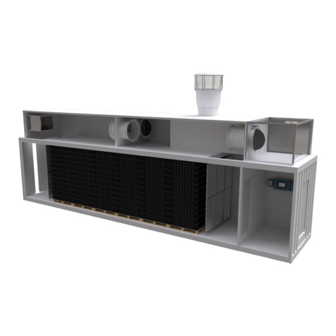
DA 60-820
Roof Inlet
Technical User Guide
604445 • 2022-03-29
English For other language variants of this document we refer to:
Español Para otras variantes del idioma de este documento, visite:
Français Pour les versions dans d'autres langues de ce document veuillez consulter:
http://docs.skov.com/1249


DA 60-820
Technical User Guide 3
Product and Documentation Changes
SKOV A/S reserves the right to change this document and the product herein described without further notice.
In case of doubt, please contact SKOV A/S.
The date of change appears from the front and back pages.
IMPORTANT!
Notes concerning alarm systems
Breakdowns, malfunctions or faulty settings may cause substantial damage and financial losses when regulat-
ing and controlling the climate in a livestock house. It is therefore essential to install a separate, independent
alarm system that monitors the house climate concurrently with the climate and production controller. According
to EU-directive No. 98/58/EU, an alarm system must be installed in all mechanically ventilated houses.
We would like to draw your attention to the fact that the product liability clause of general terms and conditions
of sale and delivery specifies that an alarm system must be installed.
Note
• All rights belong to SKOV A/S. No part of this manual may be reproduced in any manner whatsoever without
the expressed written permission of SKOV A/S in each case.
• All reasonable efforts have been made to ensure the accuracy of the information contained in this manual.
Should any mistakes or imprecise information occur in spite of this, SKOV A/S would appreciate being noti-
fied thereof.
• Irrespective of the above, SKOV A/S shall not accept any liability with regard to loss or damage caused or
alleged to be caused by reliance on any information contained herein.
• Copyright by SKOV A/S.

DA 60-820
Technical User Guide
1 Product description ....................................................................................................................................... 6
2 Product survey ............................................................................................................................................... 7
2.1 Above roof .................................................................................................................................. 8
2.2 Lead-through.............................................................................................................................. 9
2.3 Attic/section ............................................................................................................................... 9
2.4 Inlet............................................................................................................................................ 11
3 Mounting guide............................................................................................................................................. 13
3.1 Recommended tools................................................................................................................ 13
3.2 Installation examples............................................................................................................... 15
3.2.1 Placement .................................................................................................................................. 15
3.2.2 Select adhesive air jet or free air direction................................................................................. 15
3.3 Placement in the livestock house .......................................................................................... 16
3.4 Examples of placement in the house..................................................................................... 16
3.5 General drawing with roof cap ............................................................................................... 17
3.6 General drawing in the attic.................................................................................................... 18
3.7 Mounting the duct.................................................................................................................... 19
3.7.1 Shortening ducts ........................................................................................................................ 19
3.8 Mounting of roof duct and duct.............................................................................................. 20
3.9 Mounting the fan ...................................................................................................................... 21
3.10 Lead-through in ceiling ........................................................................................................... 22
3.11 Mounting in the attic................................................................................................................ 23
3.11.1 Mounting the anchorage ............................................................................................................ 23
3.11.2 Mounting the bell mouth............................................................................................................. 24
3.11.3 Mounting the net ........................................................................................................................ 24
3.12 Mounting roof sheet ................................................................................................................ 25
3.12.1 Roofing sheet in a corrugated roofing sheet construction.......................................................... 25
3.12.2 Flat roofing sheet in a sandwich panel roofing sheet construction ............................................ 25
3.13 Roof duct in roof ...................................................................................................................... 27
3.13.1 Flat roofing sheet in a corrugated steel plate construction, ridge .............................................. 28
3.13.2 Flat roofing sheet in a corrugated steel plate construction, side................................................ 29
3.13.3 Check if the top is level .............................................................................................................. 31
3.14 Mounting the roof cap ............................................................................................................. 31
3.15 Mounting the duct unit on the roofing sheet......................................................................... 33
3.16 Mounting storm protection kit on roof duct .......................................................................... 34
3.17 Foaming and sealing of the duct unit .................................................................................... 35
3.18 Mounting the outlet funnel on the adapter ............................................................................ 35
3.19 Mounting adapter on the duct ................................................................................................ 37
3.20 Mounting the intermediate and bottom plate ........................................................................ 37
3.21 Mounting the recirculation fan ............................................................................................... 39
3.22 Mounting the insulation .......................................................................................................... 40
3.23 Mounting the pull rod/suspension ......................................................................................... 41
3.24 Mounting the motor controller................................................................................................ 42
3.24.1 Position of motor controller/frequency converter ....................................................................... 42
3.24.2 Mounting distances for the motor controller/frequency converter .............................................. 42
3.24.3 Position of motor controller ........................................................................................................ 43
4 Installation guide.......................................................................................................................................... 44
4.1 Electrical connection............................................................................................................... 44
4.1.1 Mains supply dimensioning regarding harmonic distortion ........................................................ 44

DA 60-820
4.1.2 Cabling in the exhaust unit......................................................................................................... 44
4.1.3 Cabling into the LPC motor controller ........................................................................................ 44
4.2 Connection in the LPC motor controller................................................................................ 45
4.2.1 Terminals for power supply........................................................................................................ 46
4.2.2 Terminals for power supply of fan.............................................................................................. 47
4.2.3 Signal terminals ......................................................................................................................... 47
4.2.4 Terminals on relay module (accessories) .................................................................................. 47
4.3 LED indication on the motor controller/frequency converter.............................................. 48
4.4 Alarms....................................................................................................................................... 48
4.5 General information about circuit diagrams ......................................................................... 49
4.5.1 Color code.................................................................................................................................. 49
4.5.2 Power supply isolator................................................................................................................. 49
4.5.3 Letter code ................................................................................................................................. 49
4.6 Cable plans and circuit diagrams........................................................................................... 50
4.6.1 DA 820 LPC 230V...................................................................................................................... 50
4.6.1.1 Cable plan.................................................................................................................................. 50
4.6.1.2 Terminals in LPC 230 V fan ....................................................................................................... 50
4.6.1.3 Circuit diagram........................................................................................................................... 51
4.6.2 Recirculation fan ........................................................................................................................ 52
4.6.2.1 Cable plan.................................................................................................................................. 52
4.6.2.2 Connection in connection box.................................................................................................... 52
4.6.2.3 Circuit diagram........................................................................................................................... 53
4.6.2.3.1 ON/OFF ..................................................................................................................................... 53
4.6.2.3.2 Stepless ..................................................................................................................................... 54
5 Maintenance instructions ............................................................................................................................ 55
5.1 Cleaning.................................................................................................................................... 55
5.2 Recycling/Disposal .................................................................................................................. 55
6 Troubleshooting instructions ..................................................................................................................... 56
7 Technical data .............................................................................................................................................. 57
7.1 DA 820 LPC............................................................................................................................... 57
7.2 Chimney.................................................................................................................................... 59
7.3 Outlet......................................................................................................................................... 60
7.4 ErP/Ecodesign.......................................................................................................................... 61
7.5 Dimensions............................................................................................................................... 62
7.5.1 Motor controller .......................................................................................................................... 62
7.5.2 DA 820 LPC ............................................................................................................................... 62
7.5.3 Air inlet ....................................................................................................................................... 63
7.5.4 Outlet ......................................................................................................................................... 63
Technical User Guide

DA 60-820
6 Technical User Guide
1 Product description
DA 60-820 is an air intake that combines high output with low air speed in the animal zone.
DA 60-820 performs up to 16200 m3/h at 40 Pa negative pressure. The high output is created without using a
fan. The output is regulated steplessly via the a parallel motion system which makes sure that the unit opens
uniformly all the way round the unit to ensure uniform distribution of air throughout the house. When installing an
air diffusion fan, an equal pressure system with an output up to 25800 m3/h at 0 Pa per unit is achieved.
The DA 60-820 is equipped with a recirculation fan that ensures the required air jet range, even though the
amount of inbound air is reduced.
The system can be set to the air jet range required for the current time of year. In this way it is always possible
to create a combination of negative pressure and opening that provides the desired relation between output and
air speed.

DA 60-820
Technical User Guide 7
2 Product survey
With roof cap Attic space
Above roof
Lead-through
Attic/section
Inlet

DA 60-820
8 Technical User Guide
2.1 Above roof
433470 DA 60-820 roof cap gray
433464 DA 60-820 roof cap black
Is used for air inlet above the roof.
Roof cap with net prevents birds from entering the house and reduces wa-
ter ingress problems, but be aware that the performance of the chimney is
also reduced.
Supplied with a mounting set.
512084 DA 60-820 rain screen gray
As standard DA 60-820 is supplied with 2 rain screens on the roof cap.
Extra rain screens can be purchased if further reduction of ingress of rain-
water and snow is required.
434602 DA 820 roof duct gray
434603 DA 820 roof duct black
Used for roof ducts in roof, outlet cone assembly, and for wall exhaust units.
Supplied with screws, bit and DA 820 mounting guide.
434604 DA 820 duct 750 mm, gray
434605 DA 820 duct 750 mm, black
Duct without fan suspension.
Supplied with screws.
434652 DA 820 supporting ring
Use it if there are more than 1.5 meters of duct above the roof, and you use
one supporting ring for each commenced 1.5 m of duct above the roof.
You also use it to stabilize the duct by the fan in the wall exhaustion, so the
duct remains circular.
434449 DA 600/DA 820 storm protection kit
To be used if the chimney is extended by more than 1.5 m above the roof.
The storm protection kit stabilizes the chimney with steel wires between the
roof duct and the roof.
Supplied with 24 m ø4 wire.

DA 60-820
Technical User Guide 9
2.2 Lead-through
434602 DA 820 roof duct gray
434603 DA 820 roof duct black
Used for roof ducts in roof, outlet cone assembly, and for wall exhaust units.
Supplied with screws, bit and DA 820 mounting guide.
523051 Roof cloth 1.9x1.7 m, neopren, black
To be used where roofing sheets are not used.
434640 DA 820 roof sheet, side, gray
434641 DA 820 roof sheet, side, black
The roofing sheet is used for mounting on the side and is available in differ-
ent versions in terms of roofing sheet types and pitches.
434644 DA 820 roof sheet, ridge, gray
434645 DA 820 roof sheet, ridge, black
The roofing sheet is used for mounting on the ridge and is available in dif-
ferent pitches.
434093 DA 600/DA 820 kit for closure of water outlet
Used if water outlet is not required.
Includes Bostik rear stop 20 mm and Sikaflex AT Connection, gray, 600 ml.
2.3 Attic/section
433466 DA 60-820 net for attic
Protective nets are used when DA 60-820 ends in attics.
Supplied with screws and washers.
434618 DA 820 bell mouth, gray
434619 DA 820 bell mouth, black
A bell mouth is used where a swivel shutter is not required.
Supplied with screws.

DA 60-820
10 Technical User Guide
434604 DA 820 duct 750 mm, gray
434605 DA 820 duct 750 mm, black
Duct without fan suspension.
Supplied with screws.
434606 DA 820 duct with fan suspension, grey
434607 DA 820 duct with fan suspension, black
Duct (750 mm) with shoe for suspension of fan unit.
Supplied with fan suspension and screws.
Remember that ducts in the house must be insulated to counteract conden-
sation.
434608 DA 820 duct w/door 750 mm gray
Duct with door is used for servicing of fan.
Supplied with fan suspension and screws.
433465 DA 60-820 anchorage for duct
Used for lead-through in the ceiling i.e. where the ceiling does not go all the
way up to the ridge.
Supplied with mounting set.
445038 DA 820 LPC 12 fan UV 230V1 50/60Hz
The motor controller is to receive a 10-0 V signal.
Motor 1.2 kW.
The fan comes with a 2-meter cable for the wiring between motor and motor
controller.
445983 DA 820 PM motor cable 230V LPC fan 5 m can be ordered, if 2 m
is insufficient.
The power supply to the motor controller does not require a shielded cable.
It comes with motor controller, fan blades and fan suspension.
3 blade, 230 V adjustable fan.
ErP 2015 approved.

DA 60-820
Technical User Guide 11
2.4 Inlet
434606 DA 820 duct with fan suspension, grey
434607 DA 820 duct with fan suspension, black
Duct (750 mm) with shoe for suspension of fan unit.
Supplied with fan suspension and screws.
Remember that ducts in the house must be insulated to counteract conden-
sation.
433469 DA 60-820 adapter black
Is used at the transition between DA 820 duct and DA 60-920 exhaust.
Supplied with mounting set.
Remember at adapters in the house must be insulated to counteract con-
densation.
433520 DA 60-920 outlet funnel Free Flow, black
The outlet funnel and the bottom plate are made from polyurethane with a
material thickness of 30mm to counteract condensation.
Always remember to order DA 60-920 exhaust, Free Flow, accessories
(433519).
433519 DA 60-920 exhaust Free Flow, accessories
Pulling system and wire is delivered unassembled.
433521 DA 60-920 intermediate plate, black
Is supplied complete with control levers for 150mm opening.
Approx 50% of the air is led out onto the intermediate plate which reduces
the air velocity out of the air supply unit and thus also the velocity at the
floor.
The intermediate plate is supplied unassembled.

DA 60-820
12 Technical User Guide
433522 DA 60-920 recirculation fan, black
Current consumption 0.62 A.
If there are large temperature differences, poor Coanda-effect by the ceil-
ing, or if free air direction is used, a recirculation fan may lessen the effect
of inappropriate down draft.
Complete with recirculation fan, capacitor and connection box.
The recirculation fan is delivered unassembled.
433467 DA 920 insulation duct 1000 mm black
433468 DA 920 insulation duct 1500 mm black
Used for insulation of ducts in a livestock house.
Supplied with cable ties.

DA 60-820
Technical User Guide 13
3 Mounting guide
If the DA 60- 820 is installed in areas with ice/snow slide risk, the necessary measures
must be taken to avoid damage to the exhaust units and wall exhausts.
3.1 Recommended tools
A list of the recommended tools for mounting purposes can be seen below.
Item Description
Cordless drill
Screwdriver bits
Drill kit
Sealant gun
Hammer
Utility knife
Crowbar
Marker pens
Tape measure
Power shears
Combination spanner
Saw

DA 60-820
14 Technical User Guide
Item Description
Hammer drill
Jigsaw
Ladder
Screwdriver
Adjustable spanner
Socket wrench set
Allen key
Water pump pliers
Spirit level
Try square

DA 60-820
Technical User Guide 15
3.2 Installation examples
Inspect the building in relation to the drawing, paying attention to the position of DA 60-820, roof pitch and roof
type.
3.2.1 Placement
If the fresh air is coming from the open, the inlet must
be placed above the ridge to minimize the external im-
pact of the air inlet.
If the roof pitch is less than 20°, this is not necessary.
DA 60-820 can also distribute the air coming from the
attic space, when an adequate opening area has been
ensured to the attic.
0.9 - 1.0 m
Min. 0.5m
In flat-ceiling livestock houses, the DA 60-820 should be
placed as close to the ceiling as possible.
In flat-ceiling livestock houses, the exhaust unit is
placed minimum 0.5 m under DA 60-820, if possible, to
reduce the risk of direct shortcut of air between the two
units.
Min. 0.5m
C = 60 % of F C = 40 % of F
F
Place DA 60-820 as follows in livestock houses with a
sloping ceiling:
F is divided by 40% to D.
F is diviced by 60% to C.
Make sure to comply with the distance requirement of at
least 1.5 m from the edge of the outlet funnel and hori-
zontally to the ceiling. Otherwise it could give rise to
problems regarding to excessive air velocities in the ani-
mal zone.
3.2.2 Select adhesive air jet or free air direction
H
4 m
H
4 m
If the height difference to the ceiling at a distance of 4
m from DA 60-820 is:
H ≤ 1.2 m, it should be dimensioned as an adhesive
air jet
H > 1.2 m, it should be dimensioned as free air direc-
tion
As a general rule, SKOV recommends a placement so
that the air is distributed as an adhesive jet.

DA 60-820
16 Technical User Guide
3.3 Placement in the livestock house
The DA 60-820 units must be placed in the house according to the enclosed drawing; however, the placement
depends on the purlins, rafters and the like. Contact SKOV A/S if major changes are made.
DA 60-820 must be placed evenly distributed with the same distance between them throughout the house. At
the gables, the units are placed further away than half the distance between the remaining units.
Check that all DA 60-820 units can be placed freely in relation to other equipment that might be fitted after-
wards, such as feed hoist, water etc., all still in accordance with the agreement with the builder.
Pay attention to the diameter of ducts used for the DA 60-820 units when lifting them past feed
hoist, water systems etc.
3.4 Examples of placement in the house
50 meter long house with one winch motor. 50 meter long house with 2 winch motors.

DA 60-820
Technical User Guide 17
3.5 General drawing with roof cap
General drawing with references for using the various parts.
Mounting the roof cap [}31]
Mounting storm protection kit on roof duct [}34]
Mounting the duct unit on the roofing sheet [}33]
Mounting roof sheet [}25]
Roof duct in roof [}27]
Foaming and sealing of the duct unit [}35]
Mounting the duct [}19]
Mounting of roof duct and duct [}20]
Lead-through in ceiling [}22]
Mounting the insulation [}40]
Mounting the fan [}21]
Mounting adapter on the duct [}37]
Mounting the outlet funnel on the adapter [}35]
Mounting the intermediate and bottom plate [}37]
Mounting the recirculation fan [}39]

DA 60-820
18 Technical User Guide
3.6 General drawing in the attic
Mounting in the attic [}23]
Mounting the duct [}19]
Lead-through in ceiling [}22]
Mounting the insulation [}40]
Mounting the fan [}21]
Mounting adapter on the duct [}37]
Mounting the outlet funnel on the adapter
[}35]
Mounting the intermediate and bottom plate
[}37]
Mounting the recirculation fan [}39]

DA 60-820
Technical User Guide 19
3.7 Mounting the duct
Assemble the duct by applying slight pressure in order to
engage the labyrinth joint.
When several subsequent ducts are mounted, the longi-
tudinal joint must be offset one quarter of a turn so that
the ducts retain their round shape.
3.7.1 Shortening ducts
Mark where to cut the duct; then saw off the superfluous
part.
Saw off the thickening of the longitudinal labyrinth joint
from the top and 40 mm downwards.
A shortened duct must not be used for fan suspension.

DA 60-820
20 Technical User Guide
Mount he shortened part on the other duct using eight
6x23 mm screws.
3.8 Mounting of roof duct and duct
Press duct and roof duct hard together until a click
sounds.
Mount the duct using four 6x23 mm screws.
Table of contents
Other Skov Control System manuals

Skov
Skov DOL 278T User manual

Skov
Skov DOL 278 User manual

Skov
Skov DOL 278 User manual

Skov
Skov DA 3800 Installation instructions manual

Skov
Skov 278A User manual

Skov
Skov DOL 635 User manual

Skov
Skov DOL 535 User manual

Skov
Skov DOL 278AMT-1 User manual

Skov
Skov DOL 78T-1 User manual

Skov
Skov BlueControl Pig User manual