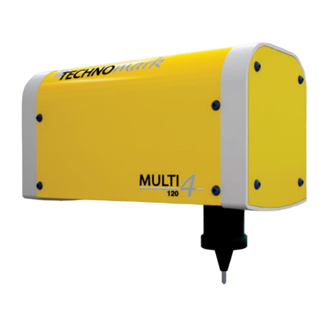
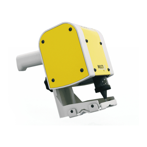
Technomark M4 inline User manual

Page 1of 44
TRAÇABILITÉ CRÉATIVE
CREATIVE TRACEABILITY
www.technomark-marking.com
Version from 04/11/2015
TECHNOMARK
3 Allée Michaël FARADAY
Parc d’activités STELYTEC
42400 SAINT-CHAMOND (France)
Tel: +33 (0) 4 77 22 25 91
Fax: + 33 (0) 4 77 22 38 93
E-mail : info@technomark-marking.com
Installation Manual
Version
Original version from 27/08/2014
Revision
1.1
Revision date
06/11/2015
Produced by
JLD
Validated by
3 Allée Michaël FARADAY
Parc d’Activités STELYTEC
42400 SAINT-CHAMOND
FRANCE
www.technomark-marking.com
Tel.: +33 (0)4 77 22 25 91
Fax: +33 (0)4 77 22 38 91

Page 2of 44
TRAÇABILITÉ CRÉATIVE
CREATIVE TRACEABILITY
www.technomark-marking.com
Version from 04/11/2015
TECHNOMARK
3 Allée Michaël FARADAY
Parc d’activités STELYTEC
42400 SAINT-CHAMOND (France)
Tel: +33 (0) 4 77 22 25 91
Fax: + 33 (0) 4 77 22 38 93
E-mail : info@technomark-marking.com
Before we start the TECHNOMARK company would like to warmly thank you for your confidence. You have chosen
the M4 Inline, the first intelligent marking tool (IDI track & mark) that is dedicated to marking integration for
ensuring your products' identification. More than just a marking machine, we offer a complete solution which
addresses all of your traceability requirements. Our customer service is at your disposal for any further information.
And so now, enjoy your marking…
CONTENTS
1. Introduction _______________________________________________________________________________ 4
2. Manuals __________________________________________________________________________________ 4
3. Certificates ________________________________________________________________________________ 4
4. Precautions of use __________________________________________________________________________ 7
5. Unpacking ________________________________________________________________________________ 9
5.1. Packaging contents _____________________________________________________________________ 9
5.1.1. Marking head ______________________________________________________________________ 9
5.1.2. Control unit _______________________________________________________________________ 9
5.2. Description of the different elements ______________________________________________________ 10
5.2.1. Marking head _____________________________________________________________________ 10
5.2.2. Head cable _______________________________________________________________________ 10
5.2.3. Quality test plate __________________________________________________________________ 12
5.2.4. Head checklist ____________________________________________________________________ 13
5.2.5. Maintenance kit (Optional accessory) __________________________________________________ 13
5.2.6. Control unit ______________________________________________________________________ 14
5.2.7. Control unit power cable (depending on country) ________________________________________ 14
5.2.8. Sub-D 25 connector ________________________________________________________________ 14
5.2.9. Control unit Checklist_______________________________________________________________ 15
5.2.10. 19 inch rack mounting plates (Optional accessory)________________________________________15
5.2.11. External keyboard _________________________________________________________________ 15
6. General presentation of the machine __________________________________________________________ 16
6.1. Control unit __________________________________________________________________________ 16
6.1.1. Dimensions_______________________________________________________________________ 16
6.1.2. Connector description ______________________________________________________________ 16
6.2. Marking head _________________________________________________________________________17
6.2.1. Possible configurations _____________________________________________________________ 17

Page 3of 44
TRAÇABILITÉ CRÉATIVE
CREATIVE TRACEABILITY
www.technomark-marking.com
Version from 04/11/2015
TECHNOMARK
3 Allée Michaël FARADAY
Parc d’activités STELYTEC
42400 SAINT-CHAMOND (France)
Tel: +33 (0) 4 77 22 25 91
Fax: + 33 (0) 4 77 22 38 93
E-mail : info@technomark-marking.com
6.2.2. Dimensions_______________________________________________________________________ 18
6.2.3. Marking window __________________________________________________________________ 19
6.3. Normal operating conditions _____________________________________________________________ 20
7. List of available accessories and options ________________________________________________________ 21
7.1. Maintenance kit (Optional accessory) ______________________________________________________ 21
7.2. External keyboard (Included in machine pack) _______________________________________________ 21
7.3. 19 inch rack mounting plates (Optional accessory) ____________________________________________ 21
7.4. Styluses and stylus guides _______________________________________________________________ 22
7.4.1. Styluses _________________________________________________________________________22
7.4.2. Stylus guides______________________________________________________________________ 22
7.5. Machine fixing kit (compatible with Multi4 ranges) ___________________________________________ 23
7.5.1. Compatibility fixing kit for Multi4 V3 standard fixing kit ____________________________________23
7.5.2. Compatibility fixing kit for reinforced Multi4 V3 fixing kit___________________________________ 23
7.5.3. Compatibility fixing kit for Multi4 V2 standard fixing kit ____________________________________23
7.5.4. Compatibility fixing kit for reinforced Multi4 V2 fixing kit___________________________________ 24
7.5.5. Compatibility fixing kit for Multi4 V1 (NAI0-4002) ________________________________________ 24
8. Equipment installation______________________________________________________________________ 25
8.1. Marking head _________________________________________________________________________25
8.1.1. Integration recommendations ________________________________________________________ 25
8.1.2. Positioning distance relative to the parts to mark_________________________________________29
8.1.3. Attaching the head_________________________________________________________________32
8.1.4. Connecting the marking head ________________________________________________________ 34
8.2. Control unit __________________________________________________________________________ 35
8.2.1. Electrical installation _______________________________________________________________ 35
8.2.2. Installation in a cabinet or on workbench _______________________________________________ 36
8.2.3. 19 inch rack installation _____________________________________________________________ 37
8.2.4. Cabling the 16-way card_____________________________________________________________ 39
9. List of illustrations _________________________________________________________________________43

Page 4of 44
TRAÇABILITÉ CRÉATIVE
CREATIVE TRACEABILITY
www.technomark-marking.com
Version from 04/11/2015
TECHNOMARK
3 Allée Michaël FARADAY
Parc d’activités STELYTEC
42400 SAINT-CHAMOND (France)
Tel: +33 (0) 4 77 22 25 91
Fax: + 33 (0) 4 77 22 38 93
E-mail : info@technomark-marking.com
1.Introduction
TECHNOMARK reserves the right to change the information and specifications contained in this manual without prior
notice. You should consult the TECHNOMARK company to learn of any changes that may have been made.
The TECHNOMARK company can in no case be held responsible for any incidental that is related to damages, direct
or indirect, or even exceptional, including but not limited to financial losses related to the use of information
contained in this manual. This clause also applies in cases where TECHNOMARK has been informed and/or has had
prior knowledge of possible risks associated with the use of the equipment.
The TECHNOMARK guarantee of the equipment it manufactures is defined in its terms and conditions. Unless
specifically stated otherwise on our acknowledgement of order receipt, our equipment is guaranteed for 1 (ONE)
year from the equipment's delivery date. This guarantee consists of our free replacement of defective parts, except
with regards to externally supplied sub-assemblies in which case the supplier's warranty is applied. This warranty
does not cover defects resulting from normal wear of the products, from incorrect use, maintenance which is not
performed in accordance with standard trade practices, inadequate storage conditions, an inappropriate product
environment, excessive use of the equipment or failure to follow the instructions for use and/or connection. Under
no circumstances will any repair work covered by the guarantee that causes a loss of time or profit will in no case
result in an extension of the guarantee.
The following are excluded from the cover:
-Stylus
-Spring
-Stylus guide
-Core
-The outer part of the cable between the control unit and the marking head or an accessory.
The information contained in this manual is confidential and remains the property of the TECHNOMARK company.
2.Manuals
The information that is required throughout your machine's lifespan is available in the following manuals:
·M4 inline Installation Manual: Contains information on unpacking and installing your equipment.
·M4 inline Software Manual: Contains the necessary information for configuring and using your marking
machine.
·Interfacing instructions for M4 inline: Contains the necessary information for establishing communication
with your equipment (RS232, Ethernet, 16-way).
·M4 inline Maintenance Manual: Contains information about servicing your machine.
3.Certificates
Your equipment is CE and OC/CB certified. You will find the certificates and associated standards in the following
pages.

Page 5of 44
TRAÇABILITÉ CRÉATIVE
CREATIVE TRACEABILITY
www.technomark-marking.com
Version from 04/11/2015
TECHNOMARK
3 Allée Michaël FARADAY
Parc d’activités STELYTEC
42400 SAINT-CHAMOND (France)
Tel: +33 (0) 4 77 22 25 91
Fax: + 33 (0) 4 77 22 38 93
E-mail : info@technomark-marking.com
Illustration 1: CE Certificate

Page 6of 44
TRAÇABILITÉ CRÉATIVE
CREATIVE TRACEABILITY
www.technomark-marking.com
Version from 04/11/2015
TECHNOMARK
3 Allée Michaël FARADAY
Parc d’activités STELYTEC
42400 SAINT-CHAMOND (France)
Tel: +33 (0) 4 77 22 25 91
Fax: + 33 (0) 4 77 22 38 93
E-mail : info@technomark-marking.com
Illustration 2: OC/CB Certificate

Page 7of 44
TRAÇABILITÉ CRÉATIVE
CREATIVE TRACEABILITY
www.technomark-marking.com
Version from 04/11/2015
TECHNOMARK
3 Allée Michaël FARADAY
Parc d’activités STELYTEC
42400 SAINT-CHAMOND (France)
Tel: +33 (0) 4 77 22 25 91
Fax: + 33 (0) 4 77 22 38 93
E-mail : info@technomark-marking.com
4.Precautions of use
Important information is included throughout this manual. They are identified by the following indications:
Your Technomark inline M4 marking machine has been designed and manufactured for industrial use. However, a
few simple precautions should be followed to optimise the use and lifespan of your marking equipment.
PLEASE READ THE FOLLOWING BOXED TEXT CAREFULLY BEFORE USING YOUR MARKING MACHINE
The Technomark marking machine must be used and installed by personnel who are trained and qualified for
this purpose.
Please follow the regulations of the country of installation.
Technomark marking systems are electrically powered. As a result there can be dangers involved when
working with or around marking machines. The follo
wing safety advice must be observed at all times:
·
Cut all power when performing a maintenance operation on the machine. The OSHA 29CFR1910
standard requires that all energy sources are cut or disconnected and that switches are locked or
labelled during cle
aning or maintenance. Make sure the equipment is installed according to OSHA
standards.
·Distance yourself from all moving parts while the machine is operating.
Your marking equipment should not be directly exposed to water spray and should never be used outdoors in
the rain when connected to the mains.
Th
Th
Th
Th
Defines additional information.
De
Defines essential information to prevent equipment damage.
De
De
De
De
DeDe
Defines essential information for user safety.
De
De

Page 8of 44
TRAÇABILITÉ CRÉATIVE
CREATIVE TRACEABILITY
www.technomark-marking.com
Version from 04/11/2015
TECHNOMARK
3 Allée Michaël FARADAY
Parc d’activités STELYTEC
42400 SAINT-CHAMOND (France)
Tel: +33 (0) 4 77 22 25 91
Fax: + 33 (0) 4 77 22 38 93
E-mail : info@technomark-marking.com
Warning, dangerous moving parts, keep fingers and other body parts at a safe distance.
When used intensively the active part of the machine (impact unit solenoid) may exceed a
temperature of 70° C. Do not work on this element without adequate protection and/or letting it cool
before servicing.
7. IT IS RECOMMENDED THAT SAFETY GLASSES BE WORN DURING THE MARKING CYCLE. Injuries can be
caused by shards from the marked surface.
8.
Because the machine operates by a succession of impacts which generates vibrations, it should be
secured in line with accepted trade practices. We also recommend placing the machine on a solid
base in order to reduce noise emission and vibrations.
9.
DO NOT PLACE YOUR HANDS UNDER THE MACHINE DURING THE MARKING OPERATION, there could
be the risk of cuts and/or jamming between the stylus and the part.
10.
DEPENDING ON THE PART TO BE MARKED AND THE DESIRED IMPACT DEPTH THE SOUND LEVEL OF
YOUR MACHINE MAY EXCEED 70dB(A). Use ear plugs during the marking phase
1. NEVER CONNECT-DISCONNECT THE MARKING HEAD WHEN THE CONTROL UNIT IS ON (especially
during marking).
Incorrect connections can seriously
damage or destroy the electronic components of your machine
and void the guarantee.
2. NEVER TIGHTEN OR LOOSEN THE KNURLED NUT ON THE IMPACT
UNIT USING PLIERS OR ANOTHER
TOOL. Manually tightening is enough.
This could severely damage your machine's electronic
s. This operation will void the unit's
guarantee.
3.
YOUR EQUIPMENT HAS BEEN DESIGNED FOR USE IN MANY SITUATIONS. REGARDLESS OF YOUR
EQUIPMENT'S USE, AVOID VIOLENT AND POWERFUL IMPACTS TO BOTH ELEMENTS THAT FORM
YOUR MACHINE. AVOID IMPACTS ON THE FRONT SECTION OF YOUR COMMAND CONTROL UNIT.
You might damage one of the keys on the keyboard or the screen.
4.
KEEP YOUR DEVICE AND ITS CABLES AWAY FROM SOURCES THAT GENERATE PARASITES (ex. :
welding machine, high frequency generating source…).
5. NEVER MARK WITH THE MACHIN
E EMPTY (WITHOUT A PART TO MARK UNDER THE MARKING
HEAD). The height between the stylus and the part to be marked must NEVER exceed 9.5mm
during marking. This operation can destroy your stylus. (See 8.1.2 Positioning di
stance relative to
the parts to mark)

Page 9of 44
TRAÇABILITÉ CRÉATIVE
CREATIVE TRACEABILITY
www.technomark-marking.com
Version from 04/11/2015
TECHNOMARK
3 Allée Michaël FARADAY
Parc d’activités STELYTEC
42400 SAINT-CHAMOND (France)
Tel: +33 (0) 4 77 22 25 91
Fax: + 33 (0) 4 77 22 38 93
E-mail : info@technomark-marking.com
5.Unpacking
5.1.Packaging contents
When only a marking head control or control unit is ordered you will receive a carton with its appropriate content.
When ordering a complete machine you will receive all the parts in a single box.
Illustration 3: Packaging
5.1.1. Marking head
·Marking head
·Head cable
·Quality test plate
·Head checklist
·Maintenance kit (Accessory –not included in the standard machine)
5.1.2. Control unit
·M4 inline control unit
·Power cable (depending on country)
·SubD 25 point male connector
·Documentation CD
·Control unit Checklist
·Control unit bay mounting set (Accessory - not included in the standard machine)
·USB keyboard (QWERTY or AZERTY depending on country)

Page 10 of 44
TRAÇABILITÉ CRÉATIVE
CREATIVE TRACEABILITY
www.technomark-marking.com
Version from 04/11/2015
TECHNOMARK
3 Allée Michaël FARADAY
Parc d’activités STELYTEC
42400 SAINT-CHAMOND (France)
Tel: +33 (0) 4 77 22 25 91
Fax: + 33 (0) 4 77 22 38 93
E-mail : info@technomark-marking.com
5.2.Description of the different elements
5.2.1. Marking head
Illustration 4: Overview of the marking head (front view)
The head is composed of different elements:
1.
Head connector (depending on the
chosen option the connector may be in
another position)
2. Protection cover:
·
Flexible for M4 inline 50 (image
opposite)
·Rigid for M4 inline 120
3. Impact unit
4. Stylus
The head is also provided with a
fixing kit
which
is not visible in this position. For more
information refer to Chapter
6.2 Marking head
.
5.2.2. Head cable
Illustration 5: Head cable
The head cable is available in three different
lengths, by default the machine is equipped
with a 3m cable, other lengths are available as
options:
·5m, reference: NOI0-0005
·10m, reference: NOI0-0006

Page 11 of 44
TRAÇABILITÉ CRÉATIVE
CREATIVE TRACEABILITY
www.technomark-marking.com
Version from 04/11/2015
TECHNOMARK
3 Allée Michaël FARADAY
Parc d’activités STELYTEC
42400 SAINT-CHAMOND (France)
Tel: +33 (0) 4 77 22 25 91
Fax: + 33 (0) 4 77 22 38 93
E-mail : info@technomark-marking.com
Illustration 6: Connector description
Connector description:
1. Control unit connector
2. Marking head connector
The use of a 10m cable can affect the performance of advanced IDI functions.
ThThTh
Th
Th
Th
Th
Th
Th
Th
ThTh

Page 12 of 44
TRAÇABILITÉ CRÉATIVE
CREATIVE TRACEABILITY
www.technomark-marking.com
Version from 04/11/2015
TECHNOMARK
3 Allée Michaël FARADAY
Parc d’activités STELYTEC
42400 SAINT-CHAMOND (France)
Tel: +33 (0) 4 77 22 25 91
Fax: + 33 (0) 4 77 22 38 93
E-mail : info@technomark-marking.com
5.2.3. Quality test plate
Your machine comes with a quality test plate produced after a test validating the machine's correct operation.
This plate includes a number of important details:
Illustration 7: M4 inline 50 Quality test plate
M4 inline 50 format
From top to bottom:
·
Test line: Datamatrix +
alphanumeric characters
·Quality control date
·Marking head serial number
·
Operator who performed the
test + product code
+
datamatrix
Illustration 8: M4 inline 120 Quality test plate
M4 inline 120 format
From top to bottom:
·Quality control date
·Product code
·
Operator who performed the
test
·
Test lines: Datamatrix +
alphanumeric characters
·
Product range + marking head
serial number
·Test line

Page 13 of 44
TRAÇABILITÉ CRÉATIVE
CREATIVE TRACEABILITY
www.technomark-marking.com
Version from 04/11/2015
TECHNOMARK
3 Allée Michaël FARADAY
Parc d’activités STELYTEC
42400 SAINT-CHAMOND (France)
Tel: +33 (0) 4 77 22 25 91
Fax: + 33 (0) 4 77 22 38 93
E-mail : info@technomark-marking.com
5.2.4. Head checklist
This checklist shows the different verifications of the marking head made before packaging:
Illustration 9: Head checklist
From top to bottom:
·Date checklist was completed
·Operator who assembled the head
·Operator who performed the inspection
·Head serial number
·
Type of head connector output (Standard or
with optional NAI0-0001)
·Window size
·Cable length
·Verification of covers and fasteners
·Verification of accessories
·Other verifications
5.2.5. Maintenance kit (Optional accessory)
Refer to the chapter 7 List of available accessories and options to learn the contents of the maintenance kit.
Illustration 10: Maintenance kit

Page 14 of 44
TRAÇABILITÉ CRÉATIVE
CREATIVE TRACEABILITY
www.technomark-marking.com
Version from 04/11/2015
TECHNOMARK
3 Allée Michaël FARADAY
Parc d’activités STELYTEC
42400 SAINT-CHAMOND (France)
Tel: +33 (0) 4 77 22 25 91
Fax: + 33 (0) 4 77 22 38 93
E-mail : info@technomark-marking.com
5.2.6. Control unit
Illustration 11: M4 inline control unit
5.2.7. Control unit power cable (depending on country)
The power cable supplied with your machine meets the standards and guidelines applicable to the equipment for
which it was tested.
5.2.8. Sub-D 25 connector
In order to connect to the M4 inline control unit 16-way card, a Sub-D 25 point male connector kit is supplied which
must be screwed in place.
See paragraph 8.2.4 Cabling the for a cabling diagram or refer to the manual Interfacing instruction for M4 inline.
Illustration 12: Sub-D 25 point connector kit

Page 15 of 44
TRAÇABILITÉ CRÉATIVE
CREATIVE TRACEABILITY
www.technomark-marking.com
Version from 04/11/2015
TECHNOMARK
3 Allée Michaël FARADAY
Parc d’activités STELYTEC
42400 SAINT-CHAMOND (France)
Tel: +33 (0) 4 77 22 25 91
Fax: + 33 (0) 4 77 22 38 93
E-mail : info@technomark-marking.com
5.2.9. Control unit Checklist
This checklist shows the different verifications of the control unit made before packaging:
Illustration 13: Control unit checklist
From top to bottom:
·Date checklist was completed
·Operator who assembled the head
·Operator who performed the inspection
·Control unit serial number
·Visual check of the control unit
(covers, screws
and feet)
·Different verifications:
oPresence of the various elements
necessary for starting the control unit
oConfiguration (Licences,window size)
5.2.10.19 inch rack mounting plates (Optional accessory)
Your control unit can be installed in a 19 inch rack using the accessory rack mounting plates (Reference: NAI0-5001).
Refer to Paragraph 8.2.3 19 inch rack installation in this manual for installation details.
Illustration 14: 19 inch rack mounting plate
5.2.11.External keyboard
Your machine comes with an external USB keyboard. Two keyboard layouts are available AZERTY (Reference: NAI0-
6000) and QWERTY (Reference: NAI0-6001).
The special characters which are available are defined in the control unit's special characters menu.
Compatibility with different keyboards that are not provided by Technomark is not guaranteed.
Th
Th
Th
Th
Th
Th

Page 16 of 44
TRAÇABILITÉ CRÉATIVE
CREATIVE TRACEABILITY
www.technomark-marking.com
Version from 04/11/2015
TECHNOMARK
3 Allée Michaël FARADAY
Parc d’activités STELYTEC
42400 SAINT-CHAMOND (France)
Tel: +33 (0) 4 77 22 25 91
Fax: + 33 (0) 4 77 22 38 93
E-mail : info@technomark-marking.com
6.General presentation of the machine
6.1.Control unit
6.1.1. Dimensions
Illustration 15: Dimensions of M4 inline control unit
6.1.2. Connector description
Illustration 16: Presentation of control unit connectors (rear view)
Connector description
1. Marking head connector
2. Power plug and ON / OFF switch
3. 12 point accessory connector
4. Sub-D 16-way 25 point female
connector
5. Ethernet Port (RJ45)
6. USB Device
7. Female serial port (RS232)
In case of a machine integrated into a system, control box must be turned off before connecting or
disconnecting the 16-way connector to prevent unexpected piloting and damaging the installation.
In
The control unit must be turned off before connecting or disconnecting the power, the header connector, the
accessory connector
and 16-way connector.
Otherwise there is a risk of irreversible material
damage.
External circuits connected to the product must be a SELV design, as defined in the IEC60950
-
1:2005 and
EN60950-1:2006/+A11 standards.
Th
Th
Th
Th
Th
Th
Th
Th
Th
Th
Th
Th
Th
Th
Th
Th
Th
Th
Th
Th
Th
Th
Th
Th
Th
Th
Th
Th

Page 17 of 44
TRAÇABILITÉ CRÉATIVE
CREATIVE TRACEABILITY
www.technomark-marking.com
Version from 04/11/2015
TECHNOMARK
3 Allée Michaël FARADAY
Parc d’activités STELYTEC
42400 SAINT-CHAMOND (France)
Tel: +33 (0) 4 77 22 25 91
Fax: + 33 (0) 4 77 22 38 93
E-mail : info@technomark-marking.com
6.2.Marking head
6.2.1. Possible configurations
The M4 inline machine exists with two different window sizes M4 inline 50 (50 x 55mm) and M4 inline 120 (120 x
55mm).
In addition to these dimensions the head connector can be either be located on the top surface of the head
(standard) or at the rear (NOI0-0001 option to be specified in the order).
Illustration 17: M4 inline head - connector on top surface
Illustration 18: M4 inline head - connector on rear surface

Page 18 of 44
TRAÇABILITÉ CRÉATIVE
CREATIVE TRACEABILITY
www.technomark-marking.com
Version from 04/11/2015
TECHNOMARK
3 Allée Michaël FARADAY
Parc d’activités STELYTEC
42400 SAINT-CHAMOND (France)
Tel: +33 (0) 4 77 22 25 91
Fax: + 33 (0) 4 77 22 38 93
E-mail : info@technomark-marking.com
6.2.2. Dimensions
6.2.2.1. M4 inline 50
Illustration 19: Dimensions of M4 inline 50 head
In this illustration the machine is shown with a standard stylus and its standard fixing kit.
Longer styluses are available as an accessory (See
7.4 Styluses and stylus guides
), as are the different
compatible
fixing kits (See 7.5 Machine fixing kit (compatible with Multi4 ranges)).
Replacing the stylus with a different model will modify the overall height.
Replacing the fixing kit with a different model will modify the overall depth.
In

Page 19 of 44
TRAÇABILITÉ CRÉATIVE
CREATIVE TRACEABILITY
www.technomark-marking.com
Version from 04/11/2015
TECHNOMARK
3 Allée Michaël FARADAY
Parc d’activités STELYTEC
42400 SAINT-CHAMOND (France)
Tel: +33 (0) 4 77 22 25 91
Fax: + 33 (0) 4 77 22 38 93
E-mail : info@technomark-marking.com
6.2.3. Marking window
The machine below is shown in solid lines when in the original position, and in dotted red lines where the impact
unit reaches the bottom of the window (position X and maximum at Y).
The overall dimensions and the dimensions of the labelling window identified by Wx are variable, depending on the
machine's window size as well as the original X position (Ox). Specific plans for each size are attached.
However the Y dimensions of the marking window remain the same for all window sizes: 55mm (2.165in).
Illustration 20: Marking window in Y
Illustration 21
: Marking window in X (rear view of machine)
M4 inline 50
M4 inline 120
Wx
50mm (1.968in)
120mm (4.724in)
Ox
29mm (1.141in)
64mm (2.519in)

Page 20 of 44
TRAÇABILITÉ CRÉATIVE
CREATIVE TRACEABILITY
www.technomark-marking.com
Version from 04/11/2015
TECHNOMARK
3 Allée Michaël FARADAY
Parc d’activités STELYTEC
42400 SAINT-CHAMOND (France)
Tel: +33 (0) 4 77 22 25 91
Fax: + 33 (0) 4 77 22 38 93
E-mail : info@technomark-marking.com
6.3.Normal operating conditions
·Power supply: 90-240 V single phase ~ 3.4A 50/60 Hz
·Temperature: 0 –45°C
·Humidity: 0 –90%
·Electromagnetic compatibility (C.E.M):
oEN55022 (2006 +A1/2007)
oEN55024 (1998 + A1/2001 + A2/2003)
oEN 61000-6-2 (2005)
·Electrical safety:
oIEC 69950-1 :2005 +/A1 :2009
oEN 60950-1 :2006 +/A11 :2009 +/A1 :2010 +/A11 :2011
Your M4 inline marking machine has unreservedly been approved, and the certified test report is available upon
request.
When used intensively the active part of the machine (impact unit solenoid) may exceed a temperature of 70°
C. Do not work on this element without adequate protection and/or letting it cool before servicing.
WhWh
Wh
Wh
Wh
Wh
This is a Class A product. In a domestic environment this product may cause radio interference, in which case it
is possible that the user wil
l be required to take adequate measures to eliminate the interference.
The control
unit's power supply must be equipped upstream with a grounded 30mA residual-
current circuit
breaker, with 16A maximum protection.
The building's electrical system will provide protection from ground faults.
Th
Th
Th
Th
Th
Th
Th
Th
Th
Th
Th
Th
Th
Th
Th
Th
Th
Th
Th
Th
Th
Th
Th
Th
Th
Th
Th
Th
Th
Th
Th
Th
Th
Th
Th
Th
Th
Th
Th
Th
Th
Th
Th
Th
Th
Th
Th
Th
This equipment has been tested and found to comply with the limits for a Class A digital device, according to
FCC
rules, Part 15. These limits are designed to provide reasonable protection against harmful interference
when the equipment is operated in a commercial environment. This equipment generates, uses and can
radiate radio frequency waves, and if not installed and used according to the instructions in the instruction
manual may cause harmful interference to radio communications. The use of this equipment in a residential
area is likely to produce harmful interference, in which case the user will be required to correct the
interference at his own expense.
ThThThTh
Th
Th
Th
Th
Th
Other manuals for M4 inline
3
Table of contents
Other Technomark Measuring Instrument manuals
Popular Measuring Instrument manuals by other brands

Endress+Hauser
Endress+Hauser Liquiline System CA80AL Brief operating instructions
BURG WATCHER
BURG WATCHER PRECISE operating instructions

ABB
ABB Relion RES670 Operator's manual
Foxwell
Foxwell BT100 user guide
Nivus
Nivus NivuSonic Clamp On instruction manual
MICRODOS
MICRODOS MP2-HT mA Programming instructions
