Nivus NivuSonic Clamp On User manual

Instruction manual
NivuSonic Clamp on
®
NivuSonic CO - Rev. 00 as of 08.12.2010 Page 1
Instruction Manual for Measurement System
NivuSonic Clamp On incl. accompanying Sensors
(Original Instruction Manual – German)
Valid as of Firmware V2.00
NIVUS GmbH
Im Taele 2
75031 Eppingen, Germany
Phone +49 (0)72 62 91 91 0
Fax +49 (0)72 62 91 91 999
E mail: info@nivus.com
Internet: www.nivus.de

®
Representatives
Page 2
NIVUS AG
Hauptstrasse 49
8750 Glarus, Switzerland
Phone +41 (0)55 / 645 20 66
Fax +41 (0)55 / 645 20 14
E mail: swiss@nivus.com
NIVUS Austria
Föhrenhaingasse 6
A 2201 Gerasdorf bei Wien
Tel.: +43 (0)2246 32319
Fax: +43 (0)2246 32386
E Mail: austria@nivus.com
Internet: www.nivus.de
NIVUS Sp. z o. o
Ul. Hutnicza 3 / B 18
81 212 Gdynia, Poland
Phone +48 (0)58 / 760 20 15
Fax +48 (0)58 / 760 20 14
E mail: biuro@nivus.pl
Internet: www.nivus.pl
NIVUS France
14, rue de la Paix
67770 Sessenheim, France
Phone +33 (0)388071696
Fax +33 (0)388071697
E mail: france@nivus.com
Internet: www.nivus.com
NIVUS U.K.
P.O. Box 342
Egerton, Bolton
Lancs. BL7 9WD, U.K.
Phone +44 (0)1204 591559
Fax +44 (0)1204 592686
E mail: info@nivus.com
Internet: www.nivus.com
NIVUS Middle East
P.O. Box 9217
Building Q 1 1 ap. 055
Sharjah Airport Int. Free Zone
Phone +971 655 78224
Fax +971 655 78225
E mail: middle east@nivus.com
Internet: www.nivus.com

Instruction manual
NivuSonic Clamp on
®
NivuSonic CO - Rev. 00 as of 08.12.2010 Page 3
Translation
If the device is sold to a country in the European Economic Area (EEA)
this instruction handbook must be translated into the language of the
country in which the device is to be used.
Should the translated text be unclear, the original instruction handbook
(German) must be consulted or the manufacturer contacted for clarifica-
tion.
Copyright
No part of this publication may be reproduced, transmitted, sold or dis-
closed without prior permission. Damages will be claimed for violations.
All rights reserved.
Names
The use of general descriptive names, trade names, trademarks and the
like in this handbook does not entitle the reader to assume they may be
used freely by everyone. They are often protected registered trademarks
even if not marked as such.

®Instruction manual
NivuSonic Clamp on
1 Contents
1.1 Table of Contents
1Contents...............................................................................4
1.1 Table of Contents..........................................................................4
2Overview and use in accordance with the requirements.6
2.1 Overview .......................................................................................6
2.2 Use in accordance with the requirements.....................................7
2.3 Specifications ................................................................................8
2.3.1 Transmitter ....................................................................................8
2.3.2 Clamp On System .........................................................................8
2.3.3 Accessories (optional)...................................................................9
3General Notes on Safety and Danger...............................10
3.1 Danger Notes ..............................................................................10
3.1.1 General Danger Signs.................................................................10
3.1.2 Special Danger Notes .................................................................10
3.2 Device Identification ....................................................................11
3.3 Installation of Spare Parts and Parts subject to wear and tear...12
3.4 Turn-off procedure.......................................................................12
3.5 User’s Responsibilities ................................................................12
4Functional Principle ..........................................................13
4.1 General........................................................................................13
4.2 Flow velocity detection ................................................................14
4.3 Flow calculation...........................................................................16
4.4 Device variations .........................................................................16
5Storing, Delivery and Transport.......................................17
5.1 Receipt ........................................................................................17
5.2 Delivery .......................................................................................17
5.3 Storing .........................................................................................18
5.4 Transport .....................................................................................18
5.5 Return..........................................................................................18
6Installation..........................................................................19
6.1 General........................................................................................19
6.2 Transmitter installation and connection.......................................19
6.2.1 General........................................................................................19
6.2.2 Enclosure dimensions .................................................................20
6.2.3 Transmitter Connection...............................................................21
6.3 Sensor Installation and connection .............................................23
6.3.1 Sensor installation.......................................................................23
6.3.2 Choosing Sensor Position and Required Distances ...................25
6.3.3 Sensor Connection......................................................................28
6.4 NivuSonic CO Power Supply ......................................................29
6.5 Overvoltage Protection Precautions............................................31
6.6 Communication ...........................................................................32
6.6.1 General........................................................................................32
6.6.2 Communication Options..............................................................34
Page 4

Instruction manual
NivuSonic Clamp on
®
6.6.3 Communication Setup and Connection via Access Portal..........35
6.6.4 Data Transmission ......................................................................37
7Initial start-up.....................................................................42
7.1 General........................................................................................42
7.2 Operator Panel ............................................................................43
7.3 Display.........................................................................................44
7.4 Operation Basics.........................................................................46
8Parameter Setting..............................................................47
8.1 Quick Guide Parameter Setting (Quick Start ) ............................47
8.2 Parameter Setting Basics............................................................48
8.3 Operation Mode (RUN) ..............................................................50
8.4 Display Menu (EXTRA) ...............................................................51
8.5 Parameter Menu (PAR)...............................................................54
8.5.1 Parameter Menu „ Measurement Place“.....................................55
8.5.2 Parameter Menu „LDV“ ...............................................................58
8.5.3 Parameter Menu "Analog Inputs"................................................60
8.5.4 Parameter Menu „Analog Outputs “ ............................................60
8.5.5 Parameter Menu „Digital Outputs“ ..............................................62
8.5.6 Parameter Menu "setup parameter"............................................65
8.5.7 Parameter Menu "Storage mode" ...............................................66
8.5.8 Data Structure on Memory Card .................................................70
8.5.9 Parameter Menu "Communication".............................................71
8.6 Signal Input/Output Menu (I/O) ...................................................77
8.6.1 I/O Menu „Analog outputs” ..........................................................77
8.6.2 I/O Menu „Digital outputs” ...........................................................78
8.6.3 I/O Menu "Sensors".....................................................................78
8.6.4 I/O Menu "Interfaces" ..................................................................79
8.6.5 I/O Menu "Memory Card" ............................................................79
8.6.6 I/O Menu Communication ...........................................................81
8.7 Calibration and Calculation Menu (CAL).....................................82
9Parameter Tree...................................................................85
10 Troubleshooting ................................................................91
11 Internet Connection Questionnaire..................................94
12 Maintenance and Cleaning................................................97
13 Emergency .........................................................................97
14 Dismantling/Disposal ........................................................97
15 Table of Pictures................................................................98
16 Index .................................................................................100
17 Appendix ..........................................................................102
18 Declaration of Conformity...............................................109
NivuSonic CO - Rev. 00 as of 08.12.2010 Page 5

®
Instruction manual
NivuSonic Clamp on
Page 6
2 Overview and use in accordance with the requirements
2.1 Overview
1 Slot with plugged memory card
2 Graphic display
3 Keypad
4 Cable glands
5 Terminal clamp housing
6 USB Port
7 Clamp on sensors (pair)
Fig. 2-1 Overview

Instruction manual
NivuSonic Clamp on
®
NivuSonic CO - Rev. 00 as of 08.12.2010 Page 7
2.2 Use in accordance with the requirements
The measurement device type NivuSonic CO including respective sensors is in-
tended to be used for continuous flow measurement in slightly polluted to clear,
clean water or equivalent media in full pipes. Here the allowed maximum values,
as specified in chapter 2.3 must be strictly kept. All cases which vary from these
conditions and are not passed by NIVUS GmbH in writing are left at owner’s risk.
The device is exclusively intended to be used for purposes as described
above.
Modifying or using the devices for other purposes without the written consent
of the manufacturer will not be considered as use in accordance with the re-
quirements.
Damages resulting from this are left at user’s risk.
The device is designed for a lifetime of approx. 10 years. After that period an
inspection in addition with a general overhaul has to be made.
For installation and initial start-up the conformity certificates and test certifi-
cates of the respective authorities must be followed.
The transmitter and the sensors always have to be installed outside of Ex-
zones!

®
Instruction manual
NivuSonic Clamp on
Page 8
2.3 Specifications
2.3.1 Transmitter
Power supply 100 to 240 V AC, +10 % / -15 %, 47 to 63 Hz
or 24 V DC ±15 %, 5 % residual fluctuation
Power consumption max. 48 VA
Wall mount enclosure
-
Material: Polycarbonate
-
Weight: approx. ca. 3700 g
-
Protection: IP 65
Operating temperature -20 °C to +50 °C
Storage temperature -30 °C to +70 °C
Max. humidity 80 %, non-condensing
Display Back-lit graphic display, 128 x 128 pixel
Operation 18 keys, dialog mode in German, English, French, Italian, Spanish, Polish,
Czech and Dutch
Outputs
-
load 500 Ohm, 12 bit resolution, accuracy better than 0.1 %
-
5 switchable relays, loadable up to 230 V AC / 2 A (cos. ϕ 0,9)
-
RJ45 for Internet communication
Data storage plug-in compact flash card up to 128 MB
Data transmission Via Compact Flash Card, Modbus TCP, integrated web server; connection
to local networks (LAN) and Wide Area Network (WAN, Internet)
via Ethernet or optional internal ISDN/GPRS or analog modem
2.3.2 Clamp On System
Measurement principle Ultrasonic transit time as clamp on system
Material PEEK and stainless steel 1.4571
Measurement frequency 1 MHz; other frequencies upon request
Velocity range ±20 m/s
Inner pipe diameter 0,08 m to 1,4 m (DN 80 to DN1400)
Protection IP 68
Operating temperature -30 °C to +80 °C (ambient temperature)
Storage temperature -30 °C bis +70 °C
Cable length 10 m
Type of cable Twinax
Outside cable diameter 8,5 mm
Sensor types Pair of sensors to clamp on pipes
Measurement uncertainty
Depending on hydraulic
conditions
-
Flow velocity (v
average
) within path ±0.1 % of measurement value
-
Flow (Q): ±1-5 % of measurement value
-
Offset velocity < ±5 mm/s
Temperature measurement using velocity of sound
Measurement range within
medium
0 °C to +80 °C
Measurement uncertainty ± 1 K

Instruction manual
NivuSonic Clamp on
®
NivuSonic CO - Rev. 00 as of 08.12.2010 Page 9
2.3.3 Accessories (optional)
Memory card Type: Compact Flash Card; storage capacity: 128 MB;
fabricator: SanDisk
Readout adapter Adapter unit for PCMCIA interface, primarily for data readout via
Laptop or Notebook
Readout unit With USB interface for connecting to PC.
Network connection via RJ45 Ethernet interface (TCP/IP), internal web
server or ModBus TCP.
Clamping system Band with a length of 10m; 2 turnbuckles for sensor installation
Evaluation software Type: NivuSoft for Windows XP / Vista / 7 for data readout, creation of hy-
drographs, average values, hour, day and month totals etc.

®
Instruction manual
NivuSonic Clamp on
Page 10
3 General Notes on Safety and Danger
3.1 Danger Notes
3.1.1 General Danger Signs
Cautions
are framed and labelled with a warning triangle.
Notes
are framed and labelled with a “hand“.
Danger by electric voltage
is framed and labelled with the Symbol on the left.
Warnings
are framed and labelled with a “STOP“-sign.
For connection, initial start-up and operation of the NivuSonic CO the following
information and higher legal regulations (e.g. in Germany VDE), such as Ex-
regulations as well as safety requirements and regulations in order to avoid ac-
cidents, must be observed.
All operations, which go beyond steps to install, to connect or to program the
device, must be carried out by NIVUS staff only due to reasons of safety and
guarantee.
3.1.2 Special Danger Notes
Please note that due to the operation in the waste water field, transmitter,
sensors and cables may be loaded with dangerous disease germs. Respec-
tive precautionary measures must be taken to avoid damage to one’s health.

Instruction manual
NivuSonic Clamp on
®
NivuSonic CO - Rev. 00 as of 08.12.2010 Page 11
3.2 Device Identification
The instructions in this manual are valid only for the type of device indicated on
the title page.
The nameplate is fixed on the bottom of the device and contains the following.
-
Name and address of manufacturer
-
CE label
-
Type and serial number
-
Year of manufacture
Fig. 3-1 NivuSonic CO nameplate
Fig. 3-2 Nameplate for Clamp on sensors, Typ NIC0
An additional nameplate protected by a transparent shrunk-on hose can be
found on each end of the fixed cable providing the following:
-
article no. of sensors
-
serial no. of sensors
It is important for enquiries and replacement part orders to specify article num-
ber as well as serial number of the respective transmitter or sensor. This en-
sures correct and quick processing.
This instruction manual is a part of the device and must be available for the
user at any time.
The safety instructions contained within must be followed.
It is strictly prohibited to disable the safety contrivances or to change the way
they work.

®
Instruction manual
NivuSonic Clamp on
Page 12
3.3 Installation of Spare Parts and Parts subject to wear and tear
We herewith particularly emphasize that replacement parts or accessories,
which are not supplied by us, are not certified by us, too. Hence, the installation
and/or the use of such products may possibly be detrimental to the device’s abil-
ity to work.
Damages caused by using non-original parts and non-original accessories are
left at user’s risk.
3.4 Turn-off procedure
For maintenance, cleaning and repairs (authorised staff personnel only) the
device shall be disconnected from mains and shall be prevented from being
turned on again unintentionally.
3.5 User’s Responsibilities
In the EEA (European Economic Area) national implementation of the frame-
work directive 89/391/EEC and corresponding individual directives, in particu-
lar the directive 89/655/EEC concerning the minimum safety and health re-
quirements for the use of work equipment by workers at work, as amended,
are to be observed and adhered to.
In Germany the Industrial Safety Ordinance of October 2002 must be ob-
served.
The customer must (where necessary) obtain any local operating permits re-
quired and observe the provisions contained therein.
In addition to this, he must observe local laws and regulations on
-
personnel safety (accident prevention regulations)
-
safety of work materials and tools (safety equipment and maintenance)
-
disposal of products (laws on wastes)
-
disposal of materials (laws on wastes)
-
cleaning (cleansing agents and disposal)
-
environmental protection
-
approvals available from local authorities
Connections:
Before operating the device the user has to ensure, that the local regulations
(e.g. for operation in channels) on installation and initial start-up are taken into
account, if this is both carried out by the user.

Instruction manual
NivuSonic Clamp on
®
NivuSonic CO - Rev. 00 as of 08.12.2010 Page 13
4 Functional Principle
4.1 General
NivuSonic CO is a non-contact, stationary measurement system for flow meas-
urement and hence is pressure-independent. The storage of detected readings
and remote access using TCP/IP is carried out via network connection, Intranet
or Internet. It is mainly designed for use in slightly polluted to clear watery fluids
of various consistencies. It can exclusively be operated in full filled channels and
pipes.
The flow velocity measurement method is based on the ultrasonic transit time
principle. Due to this reason it is indispensable for the system functionality that
the solid content (dirt particles, gas bubbles or similar) is not too high to en-
able ultrasonic signal transmission between both sensors due to reflections
and hence damping.
The NivuSonic CO uses up to two sensor pairs for flow velocity determination.
1 sensor face
2 cable gland
3 sensor housing, material stainless steel 1.4571
Fig. 4-1 Assembly of clamp on sensors incl. straps

®
Instruction manual
NivuSonic Clamp on
Page 14
4.2 Flow velocity detection
The flow velocity is determined by using the ultrasonic transit time principle.
1 Sensor 1
2 Sensor 2
Fig. 4-2 One-path transit time measurement principle
This measurement principle is based on directly measuring the transit time of
acoustic signals between two ultrasonic sensors, the so-called hydro-acoustic
converters.
A short ultrasonic impulse with a defined frequency sent towards the medium
flow direction in a defined angle requires a longer transit time than another im-
pulse being sent with the medium flow direction in an inverse angle.
The difference between the transit times is proportional to the average flow ve-
locity within the measurement path.
Flow determination is possible as soon as both cross-sectional area as well as
flow geometry of pipe or channel are known.
Presuming that C>> υ
1-2
and the flow direction is known, it is possible to ap-
proach the transit time (∆t) applying
2
2121
2
c
L
t
−−
⋅
=∆
υ
Whereat:
L
1-2
length of acoustic measurement path between sensors 1 and 2
C velocity of sound in water
υ
1-2
average flow velocity between sensors 1 and 2 along the measure-
ment path
Using two paths (instead of one as used for transit time measurement) fixed on
the outside of the pipe allows to collect more information on flow velocity and
flow can therefore be determined more accurate.

Instruction manual
NivuSonic Clamp on
®
NivuSonic CO - Rev. 00 as of 08.12.2010 Page 15
Fig. 4-3 Two-path transit time measurement principle
Investigate the velocity as described below presuming C>>υ
1-2
:
( )
−⋅
+Φ⋅
=
−−−
−
−
122121
21
21
11
cos2 tt
L
α
υ
bzw.
( )
−⋅
+Φ⋅
=
−−−
−
−
344343
43
43
t
1
t
1
cos2
L
α
υ
Presuming identical flow velocities in the paths it is possible to additionally de-
termine the deviation angle αof the flow direction in two-path installations. This
angle can be derived from a comparison between the readings from the single
paths.
Φ⋅+Φ⋅
Φ⋅−Φ⋅
=
−−−−
−−−−
43212143
43212143
sinsin
coscos
arctan
υυ
υυ
α

®
Instruction manual
NivuSonic Clamp on
Page 16
4.3 Flow calculation
In case of using single-path or two-path installations in one level under the con-
dition
AQ m⋅=
υ
Given:
υ
m
average flow velocity
A cross-sectional flow area
it is required to involve a velocity coefficient k in order to compensate the differ-
ence between measured velocity
g
υ
and average velocity
m
υ
within the cross-
sectional area.
g
m
k
υ
υ
=
Using the transit time of the signal it is possible to calculate flow subsequently as
described below:
−⋅
Φ⋅
⋅⋅=⋅⋅=
−−−
−
122121
21
11
cos2 tt
L
AkAkQ
g
υ
4.4 Device variations
NivuSonic CO transmitter and the respective flow velocity sensors are available
in different versions. The tables below provide an overview on various possibili-
ties.
Transmitters
The transmitters primarily vary in terms of power supply and data transmission
options. The current type of device is indicated by the article number, which can
be found on a weatherproof label on the bottom of the enclosure.
From this article key the type of device can be specified.
NIM- M3W Standard version with 5 relays, 4mA outputs, 4 mA inputs
Data Transmission
IN Internet communication via Intranet
MA Internet communication via internal analog modem
MI Internet communication via internal ISDN modem
MG Internet communication via GPRS
Power Supply
AC 100-240 V AC / 47-63 Hz
DC 24 V stabilised
Sensor connection
DDirect connection of sensors
Number of Paths
1
Firmware
01 Standard firmware Clamp On
NIM- M3W D 1 01
1-2 paths, max. 2 paths
Fig. 4-4 NivuSonic CO transmitter type keys

Instruction manual
NivuSonic Clamp on
®
NivuSonic CO - Rev. 00 as of 08.12.2010 Page 17
Ultrasonic sensors for NivuSonic CO
The sensors are available in various constructions and vary in terms of cable
length and connection. The article no. can be found on a nameplate on the cable
end (device side) which is protected by a transparent shrunk-on hose.
NIC0 K1L Clamp On sensor pair for connection to NivuSonic CO; range ±20 m/s
0No ATEX approval
10 10 m cable lengths, pre-configured
15 15 m cable lengths, pre-configured
20 20 m cable lengths, pre-configured
30 30 m cable lengths, pre-configured
50 50 m cable lengths, pre-configured
KConnection to NivuSonic CO transmitter
NIC0 K1L 0 K
Fig. 4-5 Type keys for clamp on sensors
5 Storing, Delivery and Transport
5.1 Receipt
Please check your delivery according to the delivery note for completeness and
intactness immediately after receipt. Any damage in transit must be instantly re-
ported to the carrier. An immediate, written report must be sent to NIVUS GmbH
Eppingen as well.
Please report any delivery incompleteness in writing to your representative or di-
rectly to NIVUS Eppingen within two weeks.
Mistakes cannot be rectified later!
5.2 Delivery
The standard delivery of the NivuSonic CO measurement system contains:
-
The instruction manual with the certificate of conformity. Here, all necessary
steps to correctly install and to operate the measurement system are listed.
-
a NivuSonic CO transmitter
-
min. two ultrasonic sensors, construction: clamp on
-
a mounting set with a clamping strap and turnbuckles for 2 sensors
-
readout software Type, NivuSoft for Windows
®
XP, Vista and Windows
®
7
Additional accessories such as memory card, card reader or similar depending
on order. Please check by using the delivery note.

®
Instruction manual
NivuSonic Clamp on
Page 18
5.3 Storing
The following storing conditions shall be strictly observed:
Transmitter: max. temperature: + 70°C
min. temperature: - 30°C
max. humidity: 80 %, non-condensing
Sensor: max. temperature: +70°C
min. temperature: - 30°C
max. humidity: 100 %
The devices must be protected from corrosive or organic solvent vapours, radio-
active radiation as well as strong electromagnetic radiation.
5.4 Transport
Sensors and Transmitter are conceived for harsh industrial conditions. Despite
this do not expose them to heavy shocks or vibrations.
Transportation must be carried out in the original packaging.
5.5 Return
The units must be returned at customer cost to NIVUS Eppingen in the
original packaging.
Otherwise the return cannot be accepted!

Instruction manual
NivuSonic Clamp on
®
6 Installation
6.1 General
Regarding electric installation the local regulations in the respective countries
(e.g. VDE 0100 in Germany) must be referred to.
The NivuSonic CO power supply must be separately protected by a 6 A slow-
blow fuse and has to be isolated from other facility parts (separate turn-off,
e.g. by using an automatic cut-out with >B< characteristics).
Before feeding the rated voltage the transmitter and sensor installation must be
correctly completed. The installation should be carried out by qualified personnel
only. Further statutory standards, regulations and technical rulings have to be
taken into account.
All outer circuits, wires and lines connected to the device must have a minimum
isolation resistance of 250 V. If the voltage exceeds 42 V DC an isolation resis-
tance with 500 kOhm min. is necessary.
The section dimension of the power supply wires must be 0.75 mm2(0.03 in2)
and must be in accordance to IEC 227 or IEC 245. The unit protection rating is
IP 65.
The maximum switching voltage on the relay contacts must not exceed 250V.
According to Ex-protection it must be checked if the devices power supplies
must be integrated into the facility’s emergency shutdown conception.
6.2 Transmitter installation and connection
6.2.1 General
The transmitter mounting place has to be selected according to certain criteria.
Please strictly avoid:
- direct sunlight (use weatherproof cover if necessary, e.g. NIVUS weather-
proof cover Art. No. ZMS0 180000)
- heat emitting objects (max. ambient temperature: +50 °C)
- objects with strong electromagnetic fields (e.g. frequency converters, con-
tactors / relays, electric motors with high rated input or similar)
- corrosive chemicals or gas
- mechanical shocks
- direct installation close to footpaths or travel ways
- vibration
- radioactive radiation
For fastening the wall mount enclosure, depending on place of mounting, use 4
machine screws size M5 in suitable length as well as the necessary nuts and
shims. Or use 4 wood screws with min. diameter 4.5 mm. These screws must
reach min. 40 mm into the wall or min. 50 mm into appropriate dowels (to be
set).
NivuSonic CO - Rev. 00 as of 08.12.2010 Page 19

®Instruction manual
NivuSonic Clamp on
The transparent door of the measurement transmitter is equipped with a protec-
tive foil for protection during transport and from scratches during assembly. This
protective foil has to be removed immediately after assembly.
If the view door with protection foil is exposed to direct sunlight for a long time,
the foil cannot be easily removed.
Cleaning of the front foil can be undertaken with spirit or if necessary with car
polish. If this is not successful, a new front door can be ordered from NIVUS
GmbH or your local representative
Never change the cable lengths of the sensors delivered since this will lead to
faulty measurements or even complete measurement failures.
6.2.2 Enclosure dimensions
Fig. 6-1 NivuSonic CO wall mount enclosure
Page 20
Table of contents
Other Nivus Measuring Instrument manuals
Nivus
Nivus NivuFlow Mobile 600 User manual
Nivus
Nivus NFP User manual
Nivus
Nivus NivuLink Compact NLC0CLOG User manual
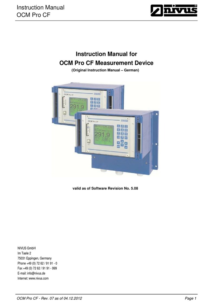
Nivus
Nivus OCM PRO CF User manual
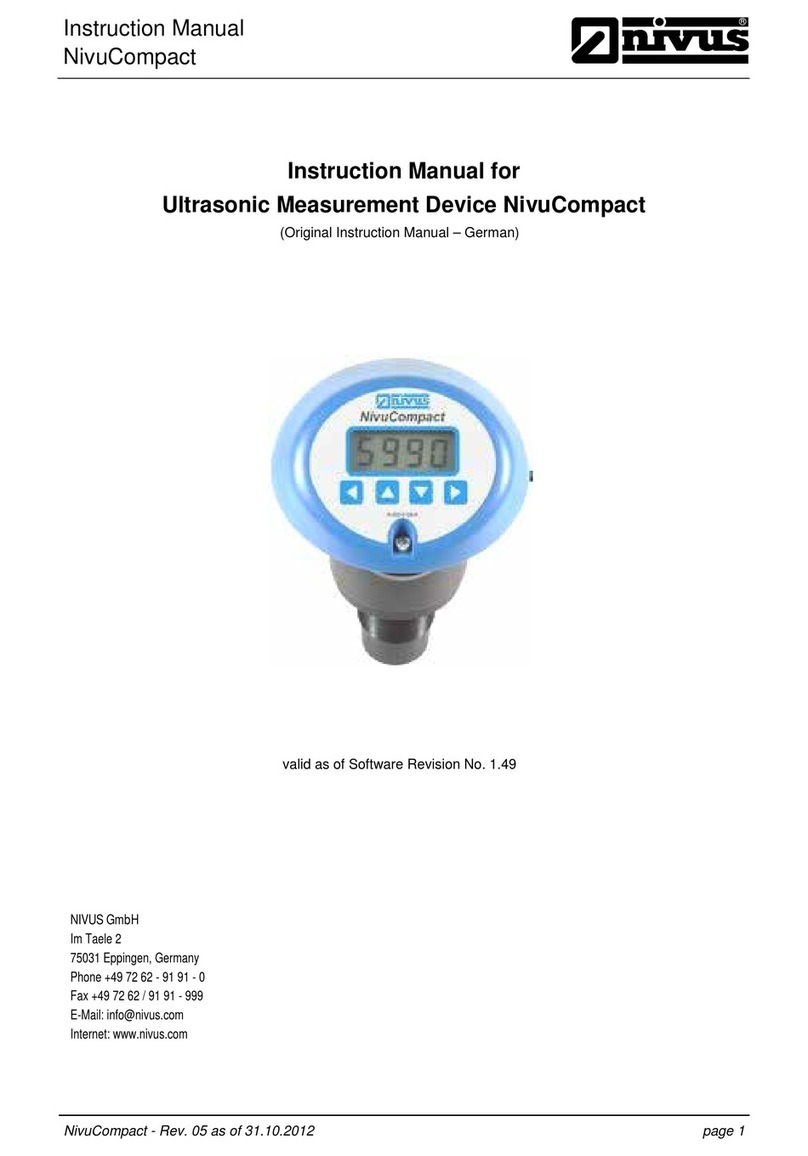
Nivus
Nivus NivuCompact User manual
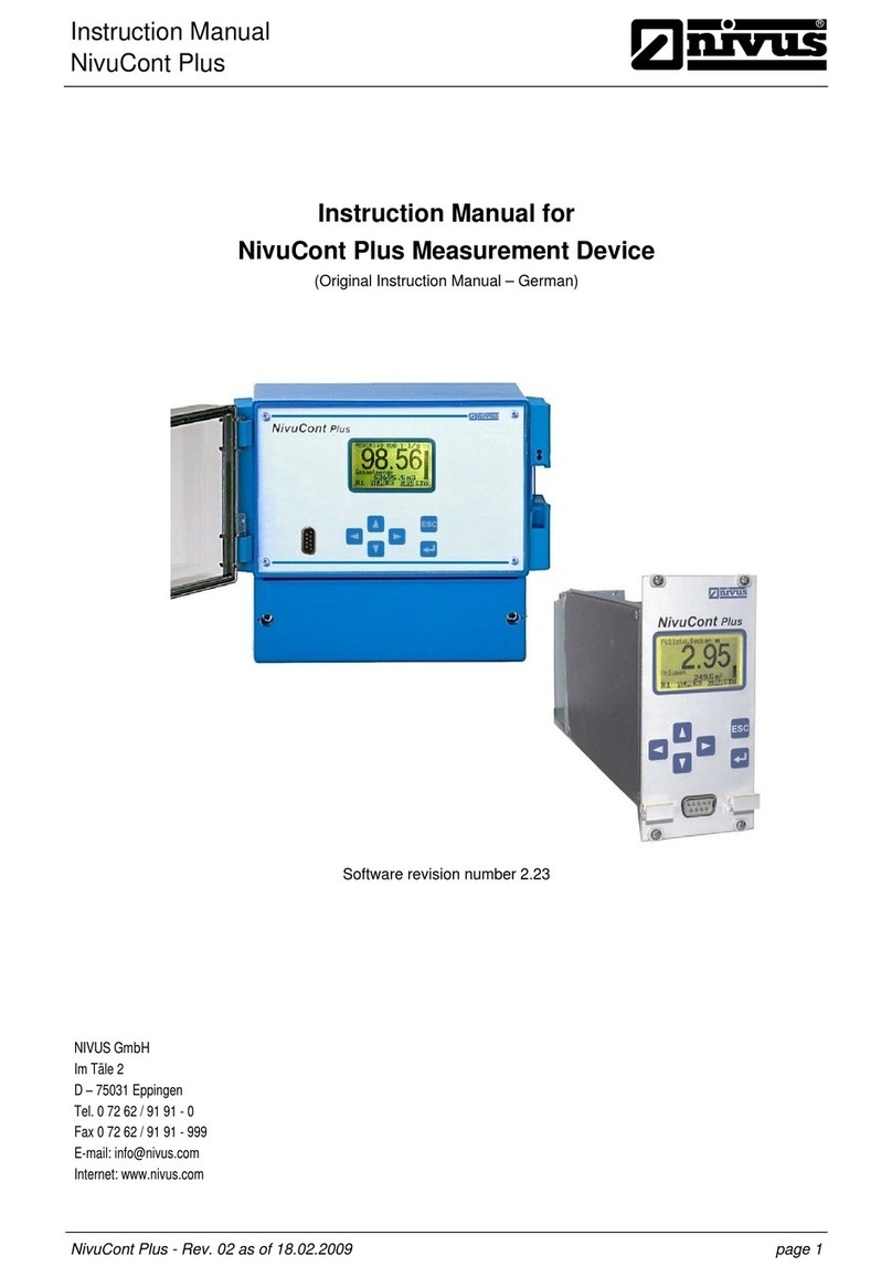
Nivus
Nivus NivuCont Plus User manual
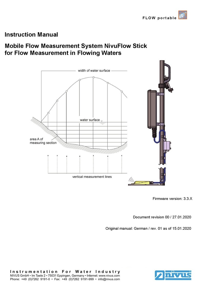
Nivus
Nivus NivuFlow Stick User manual

Nivus
Nivus NFP User manual

Nivus
Nivus OCM PRO CF User manual
Nivus
Nivus osm-f Technical manual
Popular Measuring Instrument manuals by other brands
Applent Instruments
Applent Instruments AT5220 user guide
WiMo
WiMo 6CP10 Operation and configuration instructions
Extech Instruments
Extech Instruments EX613 user guide

AquaLabo
AquaLabo NEON pH-RedOx Operation manual
DENGENSHA
DENGENSHA WS-100 instruction manual
iZ Technology
iZ Technology RADAR I Upgrade manual
