Tecnar accuraspray 4.0 User manual


This document contains information considered proprietary and confidential to Tecnar Automation Ltd
40101-00024-00– Rev E
Revision date: 2019-03-17
Page 2 of 43
User manual Accuraspray4.0
NOTICES
© 2018 Tecnar Automation Ltd.
No part of this manual may be reproduced in any form or by any means (including electronic storage and retrieval
or translation into a foreign language) without prior agreement and written consent from Tecnar Automation Ltd.
MANUAL PART
40101-00024-00
The material contained in this document is provided “as is” and is subject to change without notice in future
editions.
OVERVIEW:
• Table of content at the beginning of the document
• Table of figures at the beginning of the document
This manual contains the following sections:
• Safety
• Product description
• Installation
• Maintenance
• Operation
• Software

This document contains information considered proprietary and confidential to Tecnar Automation Ltd
40101-00024-00– Rev E
Revision date: 2019-03-17
Page 3 of 43
User manual Accuraspray4.0
TABLE OF CONTENT
1 SYSTEM DESCRIPTION ............................................................................................................................................5
1.1 INTRODUCTION ................................................................................................................................................................................... 5
1.2 GENERAL PRECAUTIONS .................................................................................................................................................................... 6
2 DESCRIPTION ...........................................................................................................................................................7
2.1 CONTROLLER ..................................................................................................................................................................................... 8
2.2 SENSOR HEAD .................................................................................................................................................................................. 10
2.3 CABLES, HOSES AND ANTENNAS ....................................................................................................................................................... 11
3 OPERATION SOFTWARE........................................................................................................................................ 12
3.1 USER INTERFACE ............................................................................................................................................................................. 12
3.2 NAVIGATION ICONS........................................................................................................................................................................... 12
3.3 LOGGING IN AS AN ADMINISTRATOR USER ........................................................................................................................................ 22
3.4 MANAGING SETUPS .......................................................................................................................................................................... 23
3.5 LOADING A SETUP ............................................................................................................................................................................ 24
3.6 TECHNICAL SPECIFICATIONS............................................................................................................................................................. 28
4 INSTALLATION ........................................................................................................................................................ 29
4.1 INSTALLING THE SENSOR HEAD ......................................................................................................................................................... 29
4.2 ACCESSING THE USER INTERFACE .................................................................................................................................................... 34
4.3 SETTING UP THE ACCURASPRAY ON A NETWORK (OPTIONAL)............................................................................................................ 35
4.4 CONNECTING THE I/OS (OPTIONAL) .................................................................................................................................................. 35
5 MAINTENANCE ....................................................................................................................................................... 37
5.1 MAINTENANCE SCHEDULE ................................................................................................................................................................ 37
5.2 MAINTENANCE PROCEDURES ........................................................................................................................................................... 38
5.3 RECOMMENDED SPARE PARTS ......................................................................................................................................................... 39
6 TROUBLESHOOTING .............................................................................................................................................. 40
6.1 SECTION TROUBLESHOOTING (LED ERROR CODES) ......................................................................................................................... 40
6.2 ERROR REPORTING IN THE USER INTERFACE .................................................................................................................................... 41
!

This document contains information considered proprietary and confidential to Tecnar Automation Ltd
40101-00024-00– Rev E
Revision date: 2019-03-17
Page 4 of 43
User manual Accuraspray4.0
TABLE OF FIGURES
FIGURE 1 SCHEMATICAL DESCRIPTION OF THE SYSTEM .............................................................................................7
FIGURE 2 CONTROLLER (FRONT) ...................................................................................................................................8
FIGURE 3 CONTROLLER (BACK) ......................................................................................................................................8
FIGURE 4 SENSOR HEAD (FRONT) ................................................................................................................................ 10
FIGURE 5 SENSOR HEAD (BACK) .................................................................................................................................. 10
FIGURE 6 ACCURASPRAY 4.0 USER INTERFACE ......................................................................................................... 12
FIGURE 7 CAMERA SCREEN .......................................................................................................................................... 14
FIGURE 8 STRIPCHART SCREEN ................................................................................................................................... 17
FIGURE 9 LOGIN WINDOW ............................................................................................................................................. 20
FIGURE 10 PASSWORD SCREEN ................................................................................................................................... 21
FIGURE 11 DIALS PROCESS CONTROL ZONES ............................................................................................................ 22
FIGURE 13 SETUP SELECTION WINDOW ...................................................................................................................... 24
FIGURE 14 SETUP OVERRIDE WINDOW ........................................................................................................................ 25
FIGURE 15 POSITION OF THE SENSOR HEAD .............................................................................................................. 30
FIGURE 16 SENSOR HEAD MONTING PLATE DIMENSIONS.......................................................................................... 30
FIGURE 17 M OUNTING THE SENSOR HEAD ................................................................................................................. 31
FIGURE 18 SENSOR HEAD INTERFACE ......................................................................................................................... 31
FIGURE 19 CONTROLLER INTERFACE .......................................................................................................................... 32
FIGURE 20 CONTROLLER STATUS LED ........................................................................................................................ 32
FIGURE 21 SENSOR HEAD ALIGNEMENT BUTTON ....................................................................................................... 33
FIGURE 22 SENSOR HEAD WORKING DISTANCE ......................................................................................................... 33
FIGURE 23 CONTROLLER ETHERNET PORT ................................................................................................................. 34
FIGURE 24 ACCURASPRAY 4.0 USER INTERFACE ....................................................................................................... 34
FIGURE 25 I/O PORT ....................................................................................................................................................... 35

This document contains information considered proprietary and confidential to Tecnar Automation Ltd
40101-00024-00– Rev E
Revision date: 2019-03-17
Page 5 of 43
User manual Accuraspray4.0
!
1 SYSTEM DESCRIPTION
1.1 INTRODUCTION
The present document gives a complete description and principle of
operation of the Accuraspray 4.0 sensor as well as a description of its
components.
1.1.1 OVERVIEW
The main purpose of the Accuraspray 4.0 is to ensure consistent, high-
quality coatings by monitoring the in-flight particles and plume properties
before each spray run. This ensures that the spray properties are within
predetermined acceptance ranges for ideal coating and performance.
To help detect potential issues such as electrode wear, partial clogging of
the nozzle or in the powder injection system, and instability of the powder
feeder before the coating process, the Accuraspray monitors:
• Particle’s temperature and velocity;
• Plume profile and intensity;
• Part temperature (optional);
The Accuraspray 4.0 can also be used to:
• Develop and optimize spray parameters;
• Transfer parameters from one booth to another (anywhere in the world);
• Transfer parameters from one spray gun to another;
• Extend the useful lifespan of hardware;
• Significantly reduce the number of test coupons;
• Troubleshoot day-to-day issues;
!
This document contains information considered proprietary and confidential to Tecnar Automation Ltd
40101-00024-00– Rev E
Revision date: 2019-03-17
Page 6 of 43
User manual Accuraspray4.0
!
1.2 GENERAL PRECAUTIONS
The following precautions should be observed at all times while operating
the Accuraspray 4.0. Tecnar Automation Ltd. assumes no liability
whatsoever for a user’s failure to comply with these precautions or the
warnings throughout this manual.
To protect your Accuraspray 4.0 from damage, you must:
• Connect it to an unloaded, properly grounded power line (50–60 Hz. 100-
240VAC, 50-60Hz, 1.5 A).
• We also recommend using an additional power line filter to filter out any
power surges or bursts;
• Use it at an ambient temperature between 4 and 45 °C;
• Supply 30 LPM (2CFM) of cooling/cleaning air at 1.7–2.7 bar (25–40 psi)
to the sensor head AT ALL TIMES while the unit is powered on.;
• Use only original spare parts.
All Accuraspray 4.0 users should read this user manual, take the web-based
introduction and training session, and contact Tecnar with any further
questions. We also recommend that a copy of the user manual be kept near
the equipment at all times.
!
This document contains information considered proprietary and confidential to Tecnar Automation Ltd
40101-00024-00– Rev E
Revision date: 2019-03-17
Page 7 of 43
User manual Accuraspray4.0
!
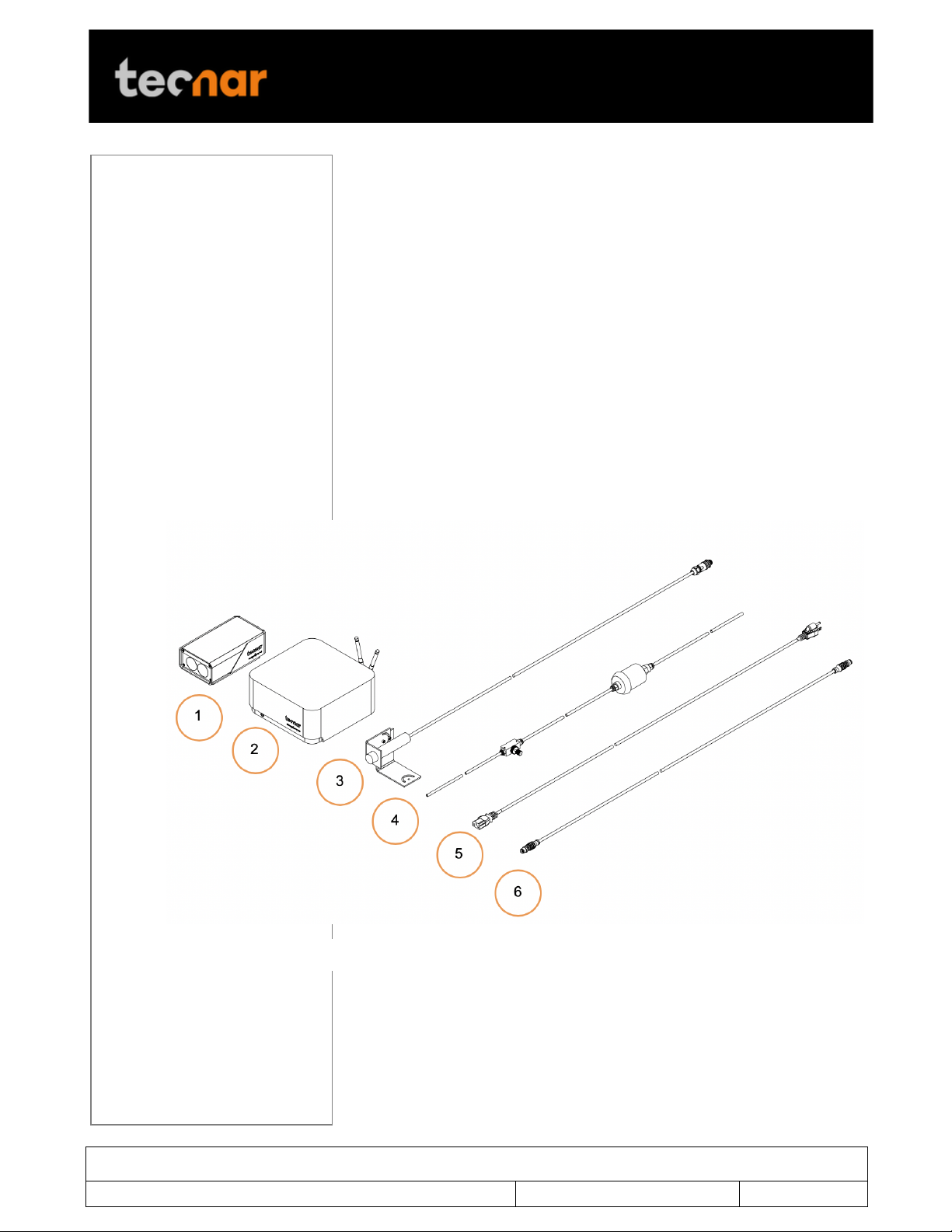
2 DESCRIPTION
The Accuraspray 4.0 system includes the following elements:
1) A sensor head;
2) A controller;
3) A substrate pyrometer (optional);
4) Air hoses and filter;
5) Controller power cable;
6) Sensor head power and communication cable;
Each elements are described in details on the following pages.
!
FIGURE 1 SCHEMATICAL DESCRIPTION OF THE SYSTEM
This document contains information considered proprietary and confidential to Tecnar Automation Ltd
40101-00024-00– Rev E
Revision date: 2019-03-17
Page 8 of 43
User manual Accuraspray4.0
!
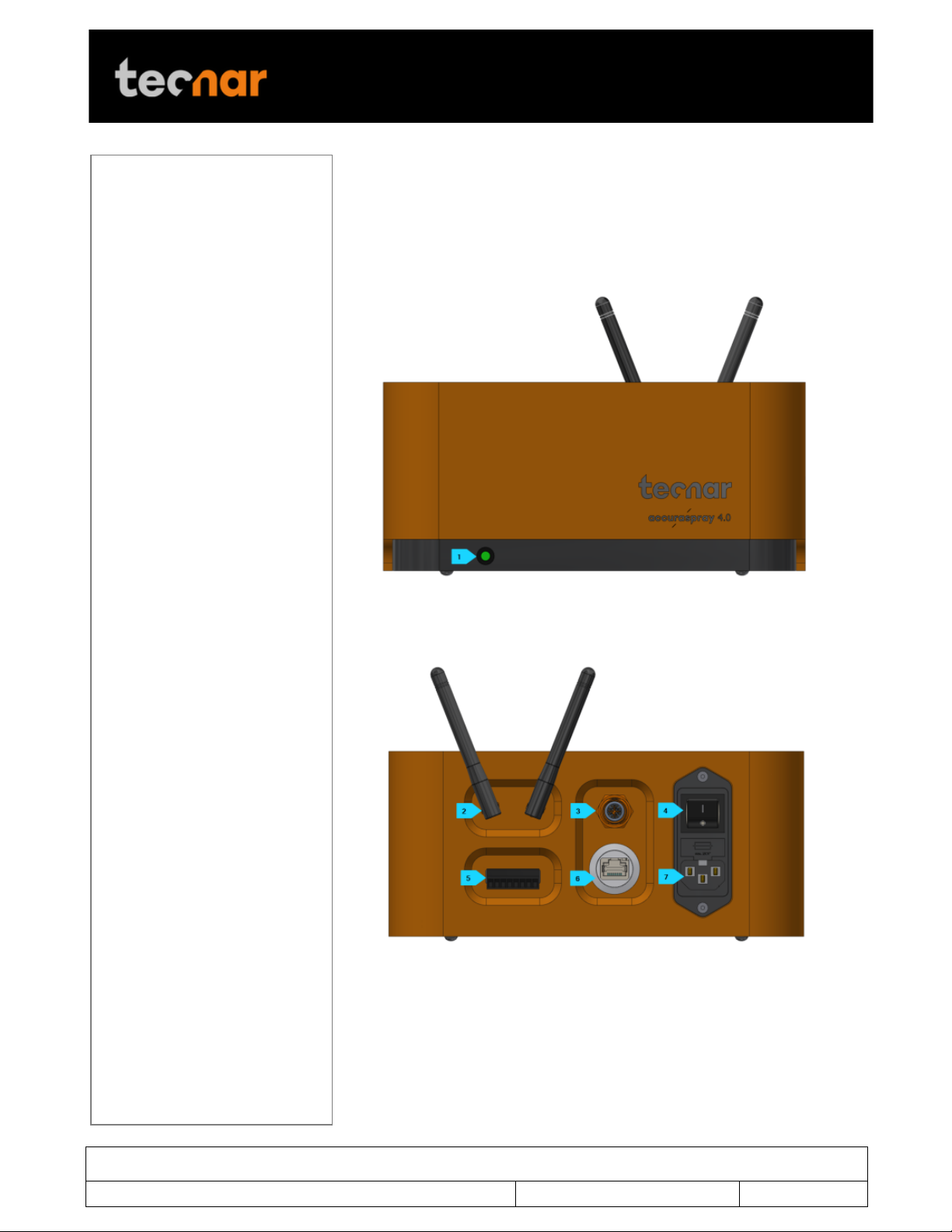
2.1 CONTROLLER
The controller must be kept in a ventilated area to reduce the risk of
overheating.
The controller receives readings from the sensor head. It processes the data
and broadcasts the results to the user interface(s).
FIGURE 2 CONTROLLER (FRONT)
FIGURE 3 CONTROLLER (BACK)

This document contains information considered proprietary and confidential to Tecnar Automation Ltd
40101-00024-00– Rev E
Revision date: 2019-03-17
Page 9 of 43
User manual Accuraspray4.0
!
Component
Description
1. LED
LED
Off: Power supply is OFF;
Green: The system is working properly;
Yellow: Sensor head is not connected;
Red: Unit power up but an error is detected.
2. Wi-Fi antenna
Used to access the Accuraspray user interface
through a wireless network connection. The
Wi-Fi connection acts as a Hotspot. It can be
disabled but not reconfigured.
3. Sensor head port
Used to power and communicate with the
sensor head.
4. Power switch
Used to active the unit.
5. User interface
port
Used to interface the Accuraspray to the user’s
spray controller via digital I/Os.
6. Ethernet
Used to access the Accuraspray user interface
through a wired network connection.
7. Power inlet
Provides power to the Accuraspray.
Connect it to an unloaded, properly grounded
power line (100-240VAC, 50-60Hz, 1.5 A).

This document contains information considered proprietary and confidential to Tecnar Automation Ltd
40101-00024-00– Rev E
Revision date: 2019-03-17
Page 10 of 43
User manual Accuraspray4.0
!
2.2 SENSOR HEAD
The sensor head measures the following particles and spray plume
properties:
• Particles velocity;
• Particles temperature;
• Spray plume geometry (width, position) and intensity.
FIGURE 4 SENSOR HEAD (FRONT)
!
FIGURE 5 SENSOR HEAD (BACK)

This document contains information considered proprietary and confidential to Tecnar Automation Ltd
40101-00024-00– Rev E
Revision date: 2019-03-17
Page 11 of 43
User manual Accuraspray4.0
!
Component
Description
1. Air knife
The air knife is used to keep the Accuraspray
windows clean and free of dust.
2. Optical system
viewport
Viewport of the temperature and velocity
measurement sensor.
3. Camera viewport
Viewport of the camera used to characterize
the plume geometry.
4. Air supply port
Compressed air is used both as active cooling
for the head’s internal components and, as it is
exhausted from the head, to generate an air
knife that keeps the viewport windows clean.
5. Alignment beam
switch
Activation switch for the alignment beam.
6. Substrate
pyrometer port
Used to power and communicate with the
optional substrate pyrometer sensor.
7. Communication
port
Used to power the sensor head and
communicate with the controller.
2.3 CABLES, HOSES AND ANTENNAS
The Accuraspray 4.0 is delivered with several cables, hoses and antennas,
which are described in the following table.
Cables/Hoses/Antennas
Description
IEC power cable
Used to connect the Accuraspray to a
power outlet.
Communication cable
Communication between the controller
and the measurement head.
Antennas
Used for WiFi communication.
Compressed air hoses
Provide compressed air to the
measurement head for cooling and
purging purposes.
• One hose connects the
compressed air supply to the air
filter;
• One hose connects the air filter to
the pressure regulator;
• One hose connects the regulator
to the measurement head;

This document contains information considered proprietary and confidential to Tecnar Automation Ltd
40101-00024-00– Rev E
Revision date: 2019-03-17
Page 12 of 43
User manual Accuraspray4.0
!
3 OPERATION SOFTWARE
3.1 USER INTERFACE
The user interface can be accessed with most internet browsers. It connects
to the controller via an Ethernet cable or Wi-Fi network.
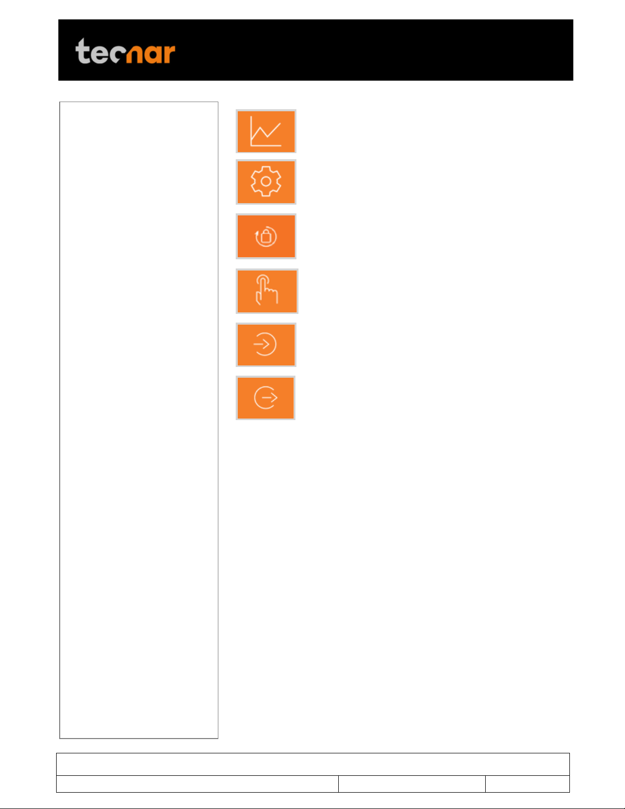
3.2 NAVIGATION ICONS
Different icons are displayed at the top of the Accuraspray user interface in
order to navigate between the different screens. The following table
describes those icons.
Icons
Description
Access the main measurement screen.
FIGURE 6 ACCURASPRAY 4.0 USER INTERFACE
This document contains information considered proprietary and confidential to Tecnar Automation Ltd
40101-00024-00– Rev E
Revision date: 2019-03-17
Page 13 of 43
User manual Accuraspray4.0
!
Access the charts screen.
Access the setup screen (Only when logged in as
Operator or Administrator)
Access the menu to change user’s passwords.
Take control and access the configuration screen
(Operators and Administrators only)
Log in.
Log out.
! !

This document contains information considered proprietary and confidential to Tecnar Automation Ltd
40101-00024-00– Rev E
Revision date: 2019-03-17
Page 14 of 43
User manual Accuraspray4.0
!
3.2.1 CAMERA SCREEN
The camera screen displays, in real time, all measurements taken by the
Accuraspray.
The measurements, are displayed at the top and to the right of the screen.
Color codes indicate whether or not the measurements are within the
acceptance range as defined in the setup by the process engineer. A
measurement fully within the acceptance range is shown in green, a
measurement just barely within the acceptance range is shown in yellow,
and a measurement outside the acceptance range is shown in red.
Corrective actions should be taken to ensure that all measurements are
within the acceptance range and displayed in green.
In the middle of the screen, in the camera view, an orange bullseye
represents the position where the particle’s temperature and velocity are
being measured. The distance between the bullseye and the tip of the spray
gun, called the standoff distance, is represented by the dotted horizontal
orange line. The green curve shows the plume intensity profile as measured
by the sensor along the vertical line.
FIGURE 7 CAMERA SCREEN

This document contains information considered proprietary and confidential to Tecnar Automation Ltd
40101-00024-00– Rev E
Revision date: 2019-03-17
Page 15 of 43
User manual Accuraspray4.0
!
The different measurements provided by the Accuraspray are described in
details in the table below.
Parameters
Description
Temperature
Average particles temperature that are passing
through the sensor’s measurement volume
(bullseye).
Velocity
Average particles speed that are passing through the
sensor’s measurement volume (bullseye).
Intensity
Intensity of the spray plume.
This measurement is very sensitive to minute
changes in the spray conditions. The parameters that
have the strongest effect on the plume intensity are:
• Particles temperature;
• Average particles diameter;
• Feedstock emissivity;
• Feed rate.
Plume density
Provides an indication of the particles flow rate.
Part temperature
Temperature of the substrate on which the coating is
applied.
Plume deviation
Deviation of the plume position against the bullseye.
Plume width
Width of the spray plume.
3.2.1.1 Zoom in / out
It is possible to zoom in on the center of the image where the bullseye is
located.
To do so, click on the magnifying glass icon. This will enlarge the image so
that the sampling line, the dotted vertical line overlaid on the camera image,
takes 50% of the screen. To return to the full screen click on the magnifying
glass again.
This feature is especially useful for HVAF/HVOF where the plume is quite
narrow and can be difficult to see when viewing the full camera frame.
3.2.1.2 Recording a video sequence
Sequences can be recorded and recalled using the icons on the top left
corner of the video. The camera icon is used to launch a recording.
Once the Accuraspray is recording, the letters in the camera will turn red to
indicate that the Accuraspray is recording.
To stop recording, click on the square icon next to the camera. This will
automatically download the sequence to your computer in your web browser
default download directory.

This document contains information considered proprietary and confidential to Tecnar Automation Ltd
40101-00024-00– Rev E
Revision date: 2019-03-17
Page 16 of 43
User manual Accuraspray4.0
!
Recorded video sequences are not stored on the Accuraspray Controller.
3.2.1.3 Playing back a video sequence
To open a saved sequence, click on the folder icon, select the sequence
that you want to replay.
As mentioned previously, the video sequences are not stored on the
Accursaspray controller. You will find them on your computer in your default
download directory or wherever you have stored them.
When replaying a sequence an X icon will appear. It is used to exit replay
mode and return back to live mode.
It is possible to pause a sequence using the Pause icon and resume
playback using the Play icon.
!! !
This document contains information considered proprietary and confidential to Tecnar Automation Ltd
40101-00024-00– Rev E
Revision date: 2019-03-17
Page 17 of 43
User manual Accuraspray4.0
!
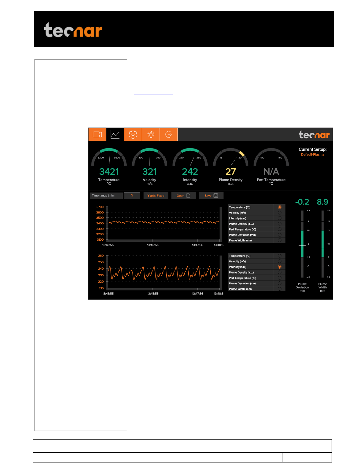
3.2.2 STRIPCHART SCREEN
The stripchart screen displays the evolution over time of measurements
available on the camera screen. For the measurement descriptions, see the
camera screen section.
In the middle of the screen are two graphs, each displaying one
measurement. It’s possible to select which measurement to display from the
table located to the right of the graphs.
3.2.2.1 Adjusting the time display
The time duration displayed on the strip charts can be adjusted using the
text box at the top of the page. The charts can display up to 60 minutes of
measurements.
The last 60 minutes are stored in the database and can be recalled at any
time.
3.2.2.2 Adjusting the Y-axis display
The range of the strip charts Y axis can be adjusted in two ways:
• Fixed - Sets the Y-axis limits (min and max values) according to the
Acceptance Ranges as defined by the setup.
FIGURE 8 STRIPCHART SCREEN

This document contains information considered proprietary and confidential to Tecnar Automation Ltd
40101-00024-00– Rev E
Revision date: 2019-03-17
Page 18 of 43
User manual Accuraspray4.0
!
• Auto – Sets the Y-axis limits (min and max values) according to the full
scale of the values captured by the sensor.
3.2.2.3 Production Reports
Production reports can be generated from the Strip Chart screen. When
users select “Save” the data contained in the strip charts and a screen
shot of the camera screen will be copied into a .pdf and .csv files.
The production reports are stored on the Accuraspray controller’s hard
drive. The directory where the files are stored is accessible by clicking on
the “Open” icon. It also contains all the strip charts. The duration of the
strip charts in the production report is the same as what was displayed in
the User interface at the time when the production report was generated.
If desired you can take the strip charts .csv file and generate your own
graphs to manipulate the data.
!! !

This document contains information considered proprietary and confidential to Tecnar Automation Ltd
40101-00024-00– Rev E
Revision date: 2019-03-17
Page 19 of 43
User manual Accuraspray4.0
!
3.2.3 LOGGING IN
The power of this interface is the ability to have multiple, simultaneous,
users (up to 5) of the software. For instance:
• One user or “the operator” can be actually be using the system for
measurement (will need to “take control” as covered in subsequent slides)
• Another user can be “watching” the “operator” from the engineering office
via the network or wireless
• Another user can be viewing saved files from previous runs in the QC
department
When accessing the Accuraspray interface, users are in viewer mode and
can only visualize the sensor’s readings like the engineer or QC person
discussed earlier.
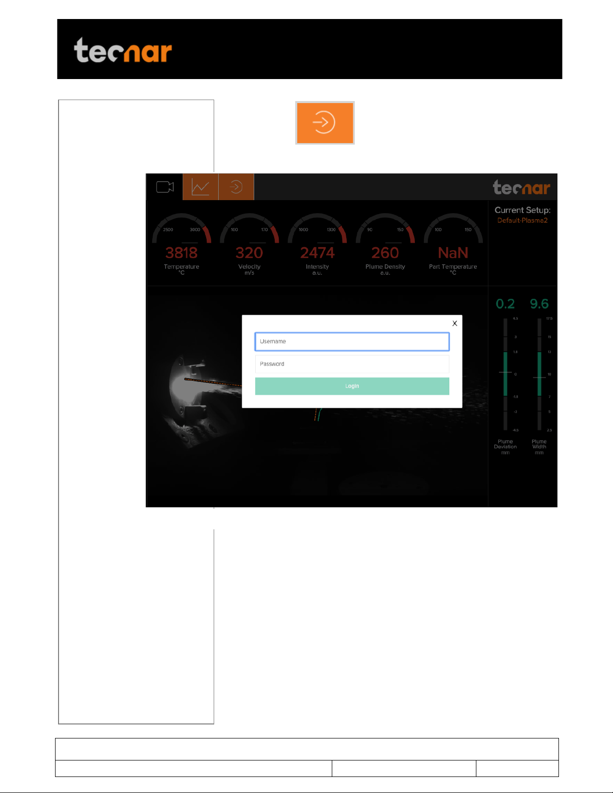
In order to actually use the sensor and record sequences it is necessary to
log in by clicking the designated icon. Users can Log in either as Operators
or Administrator.
• Operators (user name: operator) can change the setup used by the
sensor and record measurement sequences. The default password for
operators is: accura.operator
• Administrators (user name: admin) have the same rights as the
Operators and can created, modify and delete setups. The default password
for administrator is: accura.admin
This document contains information considered proprietary and confidential to Tecnar Automation Ltd
40101-00024-00– Rev E
Revision date: 2019-03-17
Page 20 of 43
User manual Accuraspray4.0
!
To log in click to display the login window and enter your
credentials
! !
FIGURE 9 LOGIN WINDOW
Other manuals for accuraspray 4.0
3
Table of contents
Other Tecnar Accessories manuals


