Tecnar Accuraspray CS User manual

User manual
In-line
cold spray
sensor

This document contains information considered proprietary and confidential to Tecnar Automation Ltee
40101-00075-00 –Rev A
Revision date: 2022-11-17
Page 1 of 51
NOTICES
© 2022 Tecnar Automation Ltd.
No part of this manual may be reproduced in any form or by any means (including electronic storage and retrieval
or translation into a foreign language) without prior agreement and written consent from Tecnar Automation Ltd.
MANUAL PART
40101-00075-00 Revision A
The material contained in this document is provided “as is” and is subject to change without notice in future
editions.
Revision: November 17th, 2022

This document contains information considered proprietary and confidential to Tecnar Automation Ltee
40101-00075-00 –Rev A
Revision date: 2022-11-17
Page 2 of 51
Table of Content
TABLE OF CONTENT................................................................................................................................................................2
LASER SAFETY ........................................................................................................................................................................5
GENERAL PRECAUTIONS ........................................................................................................................................................................ 5
AUTHORIZED USE..................................................................................................................................................................................5
CLASS 4LASER SAFETY ........................................................................................................................................................................ 5
DESCRIPTION OF CONTROLS AND SAFETY FUNCTIONS .............................................................................................................................7
SYSTEM DESCRIPTION ...........................................................................................................................................................8
INTRODUCTION......................................................................................................................................................................................8
OVERVIEW ............................................................................................................................................................................................ 8
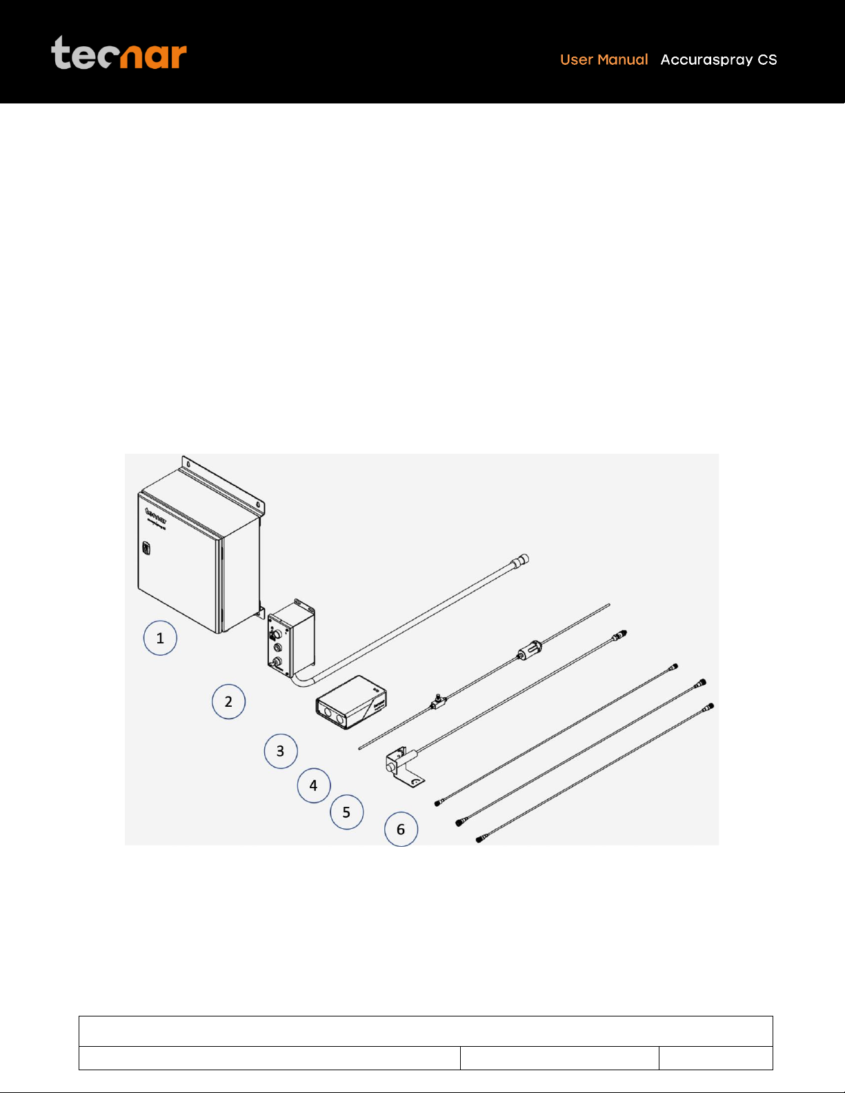
COMPONENTS DESCRIPTION ................................................................................................................................................9
CONTROLLER ...................................................................................................................................................................................... 10
SENSOR HEAD..................................................................................................................................................................................... 12
CABLES,HOSES AND ANTENNAS ........................................................................................................................................................... 14
SOFTWARE OPERATION.......................................................................................................................................................15
USER INTERFACE OVERVIEW ................................................................................................................................................................ 15
ACCESSING THE USER INTERFACE ........................................................................................................................................................ 16
CONNECTING TO THE SOFTWARE .......................................................................................................................................................... 17
LOGGING IN......................................................................................................................................................................................... 17
NAVIGATION TABS................................................................................................................................................................................ 18
LIVE SCREEN....................................................................................................................................................................................... 19
SELECTING ACTIVE GAUGES ................................................................................................................................................................. 21
ADJUSTING THE TIME SPAN................................................................................................................................................................... 22
ADJUSTING THE Y-AXIS DISPLAY ........................................................................................................................................................... 22
PART TEMPERATURE SCREEN ............................................................................................................................................................... 22
PRODUCTION REPORTS........................................................................................................................................................................ 23
SETUP SCREEN (OPERATOR AND ADMINISTRATOR ONLY) ........................................................................................................................ 24
MIN/MAX ADJUSTMENTS ....................................................................................................................................................................... 25
OPENING/DELETING SETUPS ................................................................................................................................................................ 26
SAVING SETUPS .................................................................................................................................................................................. 27
IMPORTING AND EXPORTING SETUPS ..................................................................................................................................................... 27
SETUP PARAMETERS ........................................................................................................................................................................... 28
SYSTEM SETTINGS............................................................................................................................................................................... 30
CHANGING THE USER PASSWORD ......................................................................................................................................................... 30
ENABLING/DISABLING WI-FI................................................................................................................................................................. 30
CHANGING THE STATIC IP OF THE CONTROLLER ..................................................................................................................................... 30
DHCP IP............................................................................................................................................................................................ 31
CHANGING THE PLC IP........................................................................................................................................................................ 31
REPORT GENERATION MODE ............................................................................................................................................................... 32
CHANGING THE TIME ZONE ................................................................................................................................................................... 32
UPDATING YOUR SYSTEM ..................................................................................................................................................................... 33
.................................................................................................................................................................................................33
PROCESS STABILITY.............................................................................................................................................................34
PHILOSOPHY AND MEASUREMENT PRINCIPLE ......................................................................................................................................... 34
OVERVIEW OF THE STABILITY PANEL...................................................................................................................................................... 35
THE DISTRIBUTION CHART .................................................................................................................................................................... 35

This document contains information considered proprietary and confidential to Tecnar Automation Ltee
40101-00075-00 –Rev A
Revision date: 2022-11-17
Page 3 of 51
THE CALCULATION METHODS ................................................................................................................................................................ 37
ADJUSTING THRESHOLDS BASED ON PREVIOUS RUNS ............................................................................................................................. 37
ADJUSTING THRESHOLDS MANUALLY BASED ON MULTIPLE RUNS.............................................................................................................. 37
TECHNICAL SPECIFICATIONS ..............................................................................................................................................38
SENSOR HEAD..................................................................................................................................................................................... 38
CONTROLLER ...................................................................................................................................................................................... 38
INSTALLATION........................................................................................................................................................................39
INSTALLING THE SENSOR HEAD ............................................................................................................................................................. 39
INSTALLING THE HMI MODULE .............................................................................................................................................................. 42
INSTALLING THE CONTROLLER .............................................................................................................................................................. 42
ADJUSTING THE SPRAY GUN POSITION................................................................................................................................................... 43
SETTING UP THE ACCURASPRAY ON A NETWORK (OPTIONAL) .................................................................................................................. 44
CONNECTING THE I/OS (OPTIONAL) ....................................................................................................................................................... 44
USING THE INPUT TO GENERATE REPORTS............................................................................................................................................. 44
MAINTENANCE .......................................................................................................................................................................46
MAINTENANCE SCHEDULE .................................................................................................................................................................... 46
MAINTENANCE PROCEDURES................................................................................................................................................................ 47
RECOMMENDED SPARE PARTS.............................................................................................................................................................. 48
TROUBLESHOOTING .............................................................................................................................................................49
LED ERROR CODES ............................................................................................................................................................................. 49
ERROR REPORTING IN THE USER INTERFACE.......................................................................................................................................... 50
SERVICE &SUPPORT ........................................................................................................................................................................... 51

This document contains information considered proprietary and confidential to Tecnar Automation Ltee
40101-00075-00 –Rev A
Revision date: 2022-11-17
Page 4 of 51
TABLE OF FIGURES
FIGURE 1: SCHEMATICAL DESCRIPTION OF THE SYSTEM ................................................................................................9
FIGURE 2: CONTROLLER (SIDE AND ISOMETRIC) .............................................................................................................10
FIGURE 3: SENSOR HEAD (FRONT).....................................................................................................................................12
FIGURE 4: SENSOR HEAD (BACK)........................................................................................................................................12
FIGURE 5: ACCURASPRAY CS USER INTERFACE .............................................................................................................15
FIGURE 6: ACCURASPRAY 4.0 LIVE SCREEN.....................................................................................................................19
FIGURE 7: ACTIVE GAUGES .................................................................................................................................................21
FIGURE 8: PART TEMPERATURE SCREEN .........................................................................................................................22
FIGURE 9: STRIPCHART BUTTONS BAR .............................................................................................................................23
FIGURE 10: SAVING PRODUCTION FILE..............................................................................................................................23
FIGURE 11: PRODUCTION FILES SCREEN..........................................................................................................................23
FIGURE 12: SETUP SCREEN.................................................................................................................................................24
FIGURE 13: GAUGES PROCESS CONTROL ZONES ...........................................................................................................25
FIGURE 14: OPENING/DELETING SETUPS ..........................................................................................................................26
FIGURE 15: UNSAVED SETUP MESSAGE............................................................................................................................27
FIGURE 16: SAVING SETUPS................................................................................................................................................27
FIGURE 17: IMPORT/EXPORT SETUPS................................................................................................................................27
FIGURE 18: SYSTEM SETTINGS ...........................................................................................................................................30
FIGURE 19: SYSTEM SETTINGS FOR NETWORK OPTIONS. .............................................................................................31
FIGURE 20: IO CONTROL TAB. .............................................................................................................................................32
FIGURE 21: SOFTWARE UPDATE EXAMPLE .......................................................................................................................33
FIGURE 22: STABILITY FEATURE TAB……….....……………………………………………………………………………………34
FIGURE 23: NORMAL DISTRIBUTION………………………………………………………………………………………………...35
FIGURE 24: UNPACKING THE PARTS………………………………………………………………………………………………..38
FIGURE 25: POSITION OF THE SENSOR HEAD ..................................................................................................................40
FIGURE 26: SENSOR HEAD MOUNTING PLATE DIMENSIONS. .........................................................................................40
FIGURE 27: MOUNTING THE SENSOR HEAD. .....................................................................................................................41
FIGURE 28: CABLE CONNECTIONS BETWEEN THE SENSOR HEAD AND THE CONTROLLER......................................42
FIGURE 29: SENSOR HEAD ALIGNMENT BUTTON. ............................................................................................................43
FIGURE 30: SENSOR HEAD WORKING DISTANCE. ............................................................................................................43
FIGURE 31: IO PORTS ON THE CONTROLLER....................................................................................................................44

This document contains information considered proprietary and confidential to Tecnar Automation Ltee
40101-00075-00 –Rev A
Revision date: 2022-11-17
Page 5 of 51
Laser Safety
The following precautions should be observed at all times while operating the Accuraspray CS. Tecnar Automation
Ltd. assumes no liability whatsoever for a user’s failure to comply with these precautions or the warnings
throughout this manual.
General Precautions
To protect your Accuraspray CS from damage, you must:
• Connect it to an unloaded, properly grounded power line (50–60 Hz., 100- 240VAC, 1.5 A).
• We also recommend using an additional power line filter to filter out any power surges or bursts.
• Use it at an ambient temperature between 4 and 45 °C.
• ALWAYS supply 30 LPM (2CFM) of cooling/cleaning air at 1.7–2.7 bar (25–40 psi) to the sensor head while the
unit is powered on.
• Use only original spare parts.
All Accuraspray CS users should read this user manual, take the web-based introduction and training sessions,
and contact Tecnar at servic[email protected] with any further questions. We also recommend that a copy of the
user manual should always be kept near the equipment.
Authorized Use
The Accuraspray CS is intended for use solely for cold spray process monitoring and control. Any other use is
regarded as unauthorized.
The Accuraspray CS has been designed and manufactured according to state-of-the-art technology and
recognized safety regulations. However, unauthorized use can result in danger to the operator or third parties’
body or even life and/or in damage to the product itself or other machinery.
Class 4 Laser Safety
The Accuraspray CS emits Class 4 laser radiation during operation.
Class 4 laser radiation hazards are defined as follows:
“Laser products for which intrabeam viewing and skin exposure is hazardous and for which the viewing of diffuse
reflections may be hazardous. These lasers also often represent a fire hazard.”
The Accuraspray CS contains two class 4 laser diodes with the emission overlapping at the point of measurement.

This document contains information considered proprietary and confidential to Tecnar Automation Ltee
40101-00075-00 –Rev A
Revision date: 2022-11-17
Page 6 of 51
Total laser emission:
Laser wavelength: 940 nm
Duration: Continuous wave
Nominal power: 20 W
Maximum power (fault condition): 40 W
Nominal laser density: 15.7 W/cm2
Beam divergence (each laser source): 3.3° Horizontal / 0.88° Vertical
Maximum permissible exposure: 31 W/m2
Nominal ocular hazard distance: 44 m (10 Second exposure time)
Radiation Pattern:
Both laser sources start near circular and become more elliptical the further away from the source they are.
Beam dimensions at window: 7.3mm horizontal by 6.8mm vertical.
Beam dimensions 200mm from the output: 18mm horizontal by 9mm vertical.
Eye protection:
Optical density: OD >= 4.62
Wavelength range: 900-1000nm
Radiation exposure (fault condition): 40 W

This document contains information considered proprietary and confidential to Tecnar Automation Ltee
40101-00075-00 –Rev A
Revision date: 2022-11-17
Page 7 of 51
Description of Controls and Safety Functions
1. Key Control:
The HMI Remote has a key switch which controls laser emission. When the key is removed laser emission is
disabled. The key must be inserted and turned to the ON position to be able to arm the lasers.
Note turning the key to the ON position does not automatically restart laser emissions, a manual start is required.
2. Remote Interlock Connector:
The controller has a two-channel remote interlock circuit. When the contacts are open-circuited, laser emission is
disabled. Both channels must be closed to be able to arm the lasers.
Note closing the contacts does not automatically restart laser emissions, a manual start is required.
It is recommended to use the interlock to control access to the laser environment. For example, an interlock on
the access door to the laser hazard area.
3. Sensor Head Beam Stop:
On the sensor head, a safety switch is provided. When the switch is turned to the vertical OFF position laser
emission is disabled. The switch must be turned to the vertical ON position to be able to arm the lasers.
Note turning the switch to the ON position does not automatically restart laser emissions, a manual start is required.
4. Manual Start and Stop Controls
The HMI Remote has two buttons to start and stop laser emission. If all the safety devices are clear to allow laser
emission, pressing the green button will start laser emission, and pressing the red button will stop laser emission.
The green button must be pressed to restart laser emission after any safety device has stopped emission or after
mains power to the controller has been lost.
5. Laser emission warning
The sensor head and the HMI Remote are both equipped with redundant indicator lights to indicate that the laser
is armed, and emission is possible. The lights remain on as long as the power to the laser is not completely
discharged, even if laser emission has stopped.

This document contains information considered proprietary and confidential to Tecnar Automation Ltee
40101-00075-00 –Rev A
Revision date: 2022-11-17
Page 8 of 51
System Description
Introduction
The present document gives a complete description and principle of operation of the Accuraspray CS sensor as
well as a description of its components.
Overview
The main purpose of the Accuraspray CS is to ensure consistent, high-quality coatings by monitoring the in-flight
particles and plume properties before each spray run. This ensures that the spray properties are within
predetermined acceptance ranges for ideal coating and performance.
To help detect potential issues such as partial clogging of the nozzle or in the powder injection system, and
instability of the powder feeder before the coating process, the Accuraspray CS monitors:
•Inflight particle velocity
•Relative powder feed rate
•Process Stability
•Standard deviation of all measurements
•Substrate temperature (optional)
The Accuraspray CS can also be used to:
•Develop and optimize spray parameters
•Transfer parameters from one booth to another (anywhere in the world)
•Transfer parameters from one spray gun to another
•Extend the useful lifespan of hardware
•Significantly reduce the number of test coupons
•Troubleshoot day-to-day issues

This document contains information considered proprietary and confidential to Tecnar Automation Ltee
40101-00075-00 –Rev A
Revision date: 2022-11-17
Page 9 of 51
Components Description
The Accuraspray CS system includes the following elements:
1. Controller
2. HMI unit
3. Sensor head
4. Air filter and hoses
5. Substrate pyrometer and its support bracket (optional)
6. Communication cable, laser power cable and safety switch cable
Each element is described in detail on the following pages.
FIGURE 1: SCHEMATICAL DESCRIPTION OF THE SYSTEM

This document contains information considered proprietary and confidential to Tecnar Automation Ltee
40101-00075-00 –Rev A
Revision date: 2022-11-17
Page 10 of 51
Controller
The controller must be kept in a ventilated area to reduce the risk of overheating.
The controller receives readings from the sensor head. It processes the data and broadcasts the results to the
user interface(s).
FIGURE 2: CONTROLLER (SIDE AND ISOMETRIC)

This document contains information considered proprietary and confidential to Tecnar Automation Ltee
40101-00075-00 –Rev A
Revision date: 2022-11-17
Page 11 of 51
Component
Description
1. LED
LED
Off: Power supply is OFF
Green: The system is ON
2. I/O interface
Used to interface the Accuraspray CS to the
user’s spray controller via digital I/O ports.
3. Safety interlock
Used to setup safety interlocks with the booth
access points
4. Power switch and
inlet
Used to activate the unit. Connect it to an
unloaded, properly grounded power line (100-
240VAC, 50-60Hz, 1.5 A).
5. Ethernet port
Used to access the Accuraspray CS user
interface through a wired network connection
(either static or DHCP).
6. HMI cable port
Used to connect the HMI unit with the
controller.
7. Laser power port
Used to power the lasers in the sensor head
8. Safety switch port
Used to display the status of the laser beam
stop on the UI.
9. Communication
cable port
Used to communicate with the sensor head.
10. Wi-Fi antennas
Used to access the Accuraspray CS user
interface through a wireless network
connection. The Wi-Fi connection acts as a
hotspot. It can be disabled but not
reconfigured.

This document contains information considered proprietary and confidential to Tecnar Automation Ltee
40101-00075-00 –Rev A
Revision date: 2022-11-17
Page 12 of 51
Sensor head
The sensor head measures the following particles and spray plume properties:
•Particle’s velocity
•Relative feed rate
•Process Stability
FIGURE 3: SENSOR HEAD (FRONT)
FIGURE 4: SENSOR HEAD (BACK)

This document contains information considered proprietary and confidential to Tecnar Automation Ltee
40101-00075-00 –Rev A
Revision date: 2022-11-17
Page 13 of 51
Component
Description
1. Air knife
The air knife is used to keep the sensor head
windows cleaned and free of dust.
2. Laser Illumination
Laser illumination chamber for the illumination
of the plume.
3. Detector viewport
Viewport of the detectors used to characterize
the velocity and feed rate.
4. Safety switch
connector
Used to relay information about the
mechanical shutter in the sensor head to the
controller.
5. Substrate
pyrometer
connector
Used to power and communicate with the
optional substrate pyrometer sensor.
6. Communication
port connector
Used to power the sensor head and
communicate with the controller.
7. Laser power port
connector
Used to connect the laser diodes with power.
8. Alignment beam
switch
Activation switch for the alignment beam.
9. Compressed air
port connector
Compressed air is used both as active cooling
for the head’s internal components, and as it
is exhausted from the head, to generate an air
knife that keeps the viewport windows clean.

This document contains information considered proprietary and confidential to Tecnar Automation Ltee
40101-00075-00 –Rev A
Revision date: 2022-11-17
Page 14 of 51
Cables, hoses and antennas
The Accuraspray CS is delivered with several cables, hoses, and antennas, which are described in the following
table.
Cables/Hoses/Antennas
Description
1. IEC power cable
Used to connect the Accuraspray to a
power outlet.
2. Communication cable
Communication between the controller
and the sensor head.
3. Antennas
Used for Wi-Fi communication to the
controller.
4. Safety switch cable
Used to communicate the status of the
beam stop in the sensor head
5. Laser power cable
Used to power the lasers in the sensor
head through the controller
6. Compressed air hoses
Provide compressed air to the sensor
head for cooling and purging purposes.
•One hose connects the
compressed air supply to the air
filter
•One hose connects the air filter to
the pressure regulator
•One hose connects the regulator
to the sensor head

This document contains information considered proprietary and confidential to Tecnar Automation Ltee
40101-00075-00 –Rev A
Revision date: 2022-11-17
Page 15 of 51
Software Operation
User interface overview
The Accuraspray CS user interface is accessible through a web browser, but it is not actually hosted on the
internet. It is streamed from the Accuraspray CS controller. Tecnar recommends using Google Chrome or
Microsoft Edge (chromium based) browsers.
Any modern computer with at least 4GB of RAM should be sufficient to run the user interface smoothly. Connect
the PC to the controller via an Ethernet cable or through the built-in Wi-Fi.
FIGURE 5: ACCURASPRAY CS USER INTERFACE

This document contains information considered proprietary and confidential to Tecnar Automation Ltee
40101-00075-00 –Rev A
Revision date: 2022-11-17
Page 16 of 51
Accessing the user interface
To connect to the UI through the Wi-Fi use the following steps:
1. Open the Wi-Fi menu on your computer or tablet
2. Look for “Accura CS –serial number”.
3. The password to access the Wi-Fi is “accura.wifi”.
4. Follow the procedure in the section “Modifying Windows “hosts” file” of the “40107-00047” document.
To connect to the UI through static IP use the following steps:
1. Connect the Accuraspray controller directly to your PC with an Ethernet cable.
2. Click on the Windows icon, type “View Network Connections”.
3. In the connection window, identify the connection connected to the Accuraspray.
4. Right-click on the connection and click “properties”.
5. Double-click on “Internet Protocol Version 4 (TCP/IPv4).
6. Click on “Use the following IP address”.
7. Enter the following:
IP address: 192.168.101.254
Subnet mask: 255.255.255.0
Default gateway: (leave blank)
7. Follow the procedure in the section “Modifying Windows “hosts” file” of the “40107-00047” document.
8. You are now ready to connect to the software, please refer to the section “Connecting to the software”.

This document contains information considered proprietary and confidential to Tecnar Automation Ltee
40101-00075-00 –Rev A
Revision date: 2022-11-17
Page 17 of 51
Connecting to the software
To connect to the software, use the following steps:
1. Open your browser
2. Enter the URL: http://accuracs-00000000/ to connect to the Accuraspray CS user interface. Replace the
zeros with the serial number of the unit you are trying to reach. The serial number is composed of 8 digits
which can be found in the Wi-Fi network name or under the controller.
Logging in
The Accuraspray CS user interface interface allows multiple, simultaneous users (up to 5). For instance:
•One user or “the operator” can be using the system for measurement (will need to “take control” as covered
in subsequent sections).
•Another user can be “watching” the “operator” from the engineering office via the network or wireless.
•Another user can be viewing saved files from previous runs in the QC department.
When accessing the Accuraspray CS interface, users that are not logged in are in viewer mode and can only
visualize the sensor’s readings from the live screen or the strip charts screen.
To make changes to the setup and record sequences it is necessary to log in by clicking the designated icon.
Users can log in either as operator or administrator.
•Operators (username: operator) can change (load) the setup used by the sensor and record
measurement sequences. Operators cannot modify setups. The default password for operators is:
accura.operator
•Administrators (username: admin) have the same rights as the operators and can also create,
modify, and delete setups. The default password for administrator is: accura.admin
Users’ passwords can be changed in the settings tab.

This document contains information considered proprietary and confidential to Tecnar Automation Ltee
40101-00075-00 –Rev A
Revision date: 2022-11-17
Page 18 of 51
Navigation tabs
The navigation icons are displayed on the he left of the Accuraspray CS user interface to access the different tabs.
The following table describes those icons.
Icons
Description
Access the main measurement screen (live).
Access the production files screen.
Access the setup screen (spray parameters).
Access the IO settings.
Access the substrate pyrometer screen.
Access system settings.
Take control and access the setup settings.

This document contains information considered proprietary and confidential to Tecnar Automation Ltee
40101-00075-00 –Rev A
Revision date: 2022-11-17
Page 19 of 51
Live screen
The live screen displays in real time all measurements taken by the Accuraspray CS.
The measurements are displayed at the top of the screen.
Color codes indicate whether the measurements are within the acceptance range as defined in the setup by the
process engineer. A measurement fully within the acceptance range is shown in green, a measurement just barely
within the acceptance range is shown in yellow, and a measurement outside the acceptance range is shown in
red. Corrective actions should be taken to ensure that all measurements are within the acceptance range and
displayed in green.
In the middle of the screen, you will find two graphs, each displaying one type of measurement. It is possible
to select which measurement to display from the table located to the right of the graphs .
FIGURE 6: ACCURASPRAY 4.0 LIVE SCREEN
Table of contents
Other Tecnar Accessories manuals