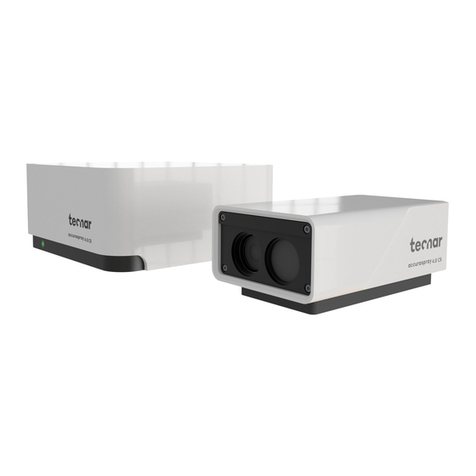
Tecnar accuraspray 4.0 User manual

1. Installing the sensor head
Where to install
Install the sensor head in the spray
booth where it is by the robot (spray
gun). Also ensure that the sensor
head does not interfere with normal
spraying operations.
Install the sensor head on a sturdy mounting plate
that does not vibrate or move during spraying.
Unpacking the parts
The box should contain the following items:
1. Sensor head
2. Controller
3. Substrate pyrometer and its support bracket (optional)
4. Air filter and hoses
5. Controller power cable
6. Communication cable between the head and controller
7. Wi-Fi antennas
8. Spare fuses (not pictured below)
9. Neutral density filters (not pictured below)
10. Calibration sheets (not pictured below)
Carefully open the box,
remove the content
pictured below, and
set it on a work surface.
Before
you begin
1. Installing the sensor head
1
2
3
4
5
6
7
1
1
2
2
3
3
4
4
A A
B B
STANDARD TOLERANCES: (UNLESS OTHERWISE NOTED)
ANGULAR: ±1° .XX:±.01
FRACTIONAL:±1/32 .XXX:±.005
INCHES METRIC
ALL INFORMATION CONTAINED IN THIS DOCUMENT ARE PROPRIETARY AND CONFIDENTIAL.
COPYRIGHT, ALL RIGHTS RESERVED.
ANGULAR X.:±0.5
X°:±1° .X:±0.3
X.X°:±0.5° .XX:±0.1
A
DRAWING SIZE:
B
REV :
sensor with gun and
spray
1 OF 2
TITLE:
ITEM:
1321 Hocquart
St-Bruno, Qc, J3V 6B5
Tel: 450-461-1221
Fax: 450-461-0808
www.tecnar.com
SHEET:
1 / 2
SCALE:
NOTES:
1. UNLESS OTHERWISE NOTED, ALL
DIMENSIONS ARE IN MILLIMETERS.
2. REMOVE ALL SHARP EDGES AND
BURRS.
4.0
Quick set-up guide
Online monitoring of thermal spray
processes for the shop floor

4. Installing the controller
3.
Adjusting the sensor head
2. Installation procedure
Attach the sensor
head to your support
bracket using
the 4 mounting
holes.
1
1
2
2
3
3
4
4
A A
B B
STANDARD TOLERANCES: (UNLESS OTHERWISE NOTED)
ANGULAR: ±1°.XX:±.01
FRACTIONAL:±1/32 .XXX:±.005
INCHES METRIC
ALL INFORMATION CONTAINED IN THIS DOCUMENT ARE PROPRIETARY AND CONFIDENTIAL.
COPYRIGHT, ALL RIGHTS RESERVED.
ANGULAR X.:±0.5
X°:±1°.X:±0.3
X.X°:±0.5°.XX:±0.1
A
DRAWING SIZE:
B
REV :
assy sensor w client
supplied baseplate
1 OF 1
TITLE:
ITEM:
1321 Hocquart
St-Bruno, Qc, J3V 6B5
Tel: 450-461-1221
Fax: 450-461-0808
www.tecnar.com
SHEET:
1/2
SCALE:
NOTES:
1. UNLESS OTHERWISE NOTED, ALL
DIMENSIONS ARE IN MILLIMETERS.
2. REMOVE ALL SHARP EDGES AND
BURRS.
REVISION HISTORY
REV DESCRIPTION DRAWING CHECKED BY DATE
A ORIGINAL ISSUE 2018-12-20
Connect the
compressed air
supply and the
communication cable
to the sensor head.
Pull the other end of
the communication
cable out of the
spray booth.
Connect the air
hose to the
booth air supply.
1
1
2
2
3
3
4
4
A A
B B
STANDARD TOLERANCES: (UNLESS OTHERWISE NOTED)
ANGULAR: ±1°.XX:±.01
FRACTIONAL:±1/32 .XXX:±.005
INCHES METRIC
ALL INFORMATION CONTAINED IN THIS DOCUMENT ARE PROPRIETARY AND CONFIDENTIAL.
COPYRIGHT, ALL RIGHTS RESERVED.
ANGULAR X.:±0.5
X°:±1°.X:±0.3
X.X°:±0.5°.XX:±0.1
A
DRAWING SIZE:
B
ACCURA\G4\MAIN ASSY
REV :
30201-01588-03
1 OF 1
TITLE:
ITEM:
1321 Hocquart
St-Bruno, Qc, J3V 6B5
Tel: 450-461-1221
Fax: 450-461-0808
www.tecnar.com
SHEET:
1 / 2
SCALE:
NOTES:
1. UNLESS OTHERWISE NOTED, ALL
DIMENSIONS ARE IN MILLIMETERS.
2. REMOVE ALL SHARP EDGES AND
BURRS.
REVISION HISTORY
REV DESCRIPTION DRAWING CHECKED BY DATE
A ORIGINAL ISSUE 2018-12-19
1
1
2
2
3
3
4
4
A A
B B
STANDARD TOLERANCES: (UNLESS OTHERWISE NOTED)
ANGULAR: ±1°.XX:±.01
FRACTIONAL:±1/32 .XXX:±.005
INCHES METRIC
ALL INFORMATION CONTAINED IN THIS DOCUMENT ARE PROPRIETARY AND CONFIDENTIAL.
COPYRIGHT, ALL RIGHTS RESERVED.
ANGULAR X.:±0.5
X°:±1°.X:±0.3
X.X°:±0.5°.XX:±0.1
A
DRAWING SIZE:
B
ACCURA G4\CONTROLER
REV :
30201-01615-02
1 OF 3
TITLE:
ITEM:
1321 Hocquart
St-Bruno, Qc, J3V 6B5
Tel: 450-461-1221
Fax: 450-461-0808
www.tecnar.com
SHEET:
1 / 4
SCALE:
5. Adjusting the spray gun position
6.
Accessing the user interface
1
1
2
2
3
3
4
4
A A
B B
STANDARD TOLERANCES: (UNLESS OTHERWISE NOTED)
ANGULAR: ±1°.XX:±.01
FRACTIONAL:±1/32 .XXX:±.005
INCHES METRIC
ALL INFORMATION CONTAINED IN THIS DOCUMENT ARE PROPRIETARY AND CONFIDENTIAL.
COPYRIGHT, ALL RIGHTS RESERVED.
ANGULAR X.:±0.5
X°:±1°.X:±0.3
X.X°:±0.5°.XX:±0.1
A
DRAWING SIZE:
B
ACCURA G4\CONTROLER
REV :
30201-01615-02
1 OF 3
TITLE:
ITEM:
1321 Hocquart
St-Bruno, Qc, J3V 6B5
Tel: 450-461-1221
Fax: 450-461-0808
www.tecnar.com
SHEET:
1 / 4
SCALE:
Activate the alignment
beam by pushing
the on button located
at the back of the sensor.
Bring the spray gun
near the sensor head
as shown on the
schematic below. The sensor
measurement point is normally set to
your standard process spray distance.
The distance between
the front of the sensor head
and the spray torch axis
should be adjusted to 200 mm.
1
1
2
2
3
3
4
4
A A
B B
STANDARD TOLERANCES: (UNLESS OTHERWISE NOTED)
ANGULAR: ±1° .XX:±.01
FRACTIONAL:±1/32 .XXX:±.005
INCHES METRIC
ALL INFORMATION CONTAINED IN THIS DOCUMENT ARE PROPRIETARY AND CONFIDENTIAL.
COPYRIGHT, ALL RIGHTS RESERVED.
ANGULAR X.:±0.5
X°:±1° .X:±0.3
X.X°:±0.5° .XX:±0.1
A
DRAWING SIZE:
B
REV :
sensor with gun and
spray
2 OF 2
TITLE:
ITEM:
1321 Hocquart
St-Bruno, Qc, J3V 6B5
Tel: 450-461-1221
Fax: 450-461-0808
www.tecnar.com
SHEET:
1 / 2
SCALE:
Standard spray
distance
Sensor
working
distance
200mm
1
1
2
2
3
3
4
4
A A
B B
STANDARD TOLERANCES: (UNLESS OTHERWISE NOTED)
ANGULAR: ±1°.XX:±.01
FRACTIONAL:±1/32 .XXX:±.005
INCHES METRIC
ALL INFORMATION CONTAINED IN THIS DOCUMENT ARE PROPRIETARY AND CONFIDENTIAL.
COPYRIGHT, ALL RIGHTS RESERVED.
ANGULAR X.:±0.5
X°:±1°.X:±0.3
X.X°:±0.5°.XX:±0.1
A
DRAWING SIZE:
B
REV :
assy sensor w client
supplied baseplate
1 OF 1
TITLE:
ITEM:
1321 Hocquart
St-Bruno, Qc, J3V 6B5
Tel: 450-461-1221
Fax: 450-461-0808
www.tecnar.com
SHEET:
1/2
SCALE:
NOTES:
1. UNLESS OTHERWISE NOTED, ALL
DIMENSIONS ARE IN MILLIMETERS.
2. REMOVE ALL SHARP EDGES AND
BURRS.
REVISION HISTORY
REV DESCRIPTION DRAWING CHECKED BY DATE
A ORIGINAL ISSUE 2018-12-20
The Accuraspray 4.0 user interface is accessible
through a web browser but it is not actually hosted
on the internet. It is streamed from the Accuraspray
controller. We recommend using Google Chrome for
optimal performance.
Go to the normal Wi-Fi menu on your computer or tablet
and look for “Accura 4.0 – serial number”. The password
to access the Wi-Fi is “accura.wifi”.
Open your browser and enter the URL:
http://accurag4-00000000/ to connect to the
Accuraspray user interface. Replace the zeros
with the serial number of the unit you are trying
to connect. The serial number consists of 8 digits
which can be found in the Wi-Fi network name
or under the controller.
Alignment
beam switch
You are now ready for your free online training.
Please contact us at service@tecnar.com to book
your appointment.
See the Accuraspray 4.0 user’s manual for complete
system description. www.spraysensors.tecnar.com/
accuraspray4-usermanual
Where to install
Install the controller outside
the spray booth.
Installation
procedure
Install the Wi-Fi
antennas on
the controller.
Connect the sensor head
communication cable.
Connect the power cable
to the controller and into
a power socket. Flip the
Accuraspray controller
power switch to ON.
Wait until the
status LED
turns green.
Power
outlet
Power
switch
Communication
cable
Wi-Fi
antennas
Status
LED
Provide
access
Supplied
by the user
Supplied
with the
Accuraspray 4.0
Air supply
Communicaton
cable
Other manuals for accuraspray 4.0
3
Other Tecnar Accessories manuals
Popular Accessories manuals by other brands
Holman
Holman WXMS user guide
B.E.G. LUXOMAT
B.E.G. LUXOMAT PD1-M-2C Installation and operating instruction manual
PCB Piezotronics
PCB Piezotronics 117B67 Installation and operating manual

Motorline professional
Motorline professional COFRE 260 installer and user manual
Waycon
Waycon MAP Series installation guide
Fluke
Fluke 80K-15 instruction sheet
