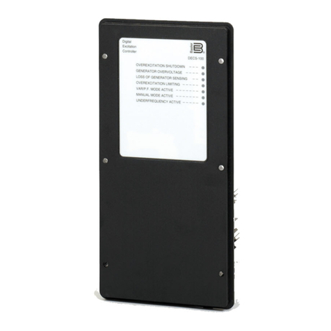
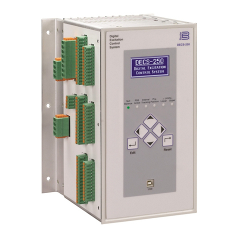
Basler DECS-250 User manual

DECS-250 Digital Excitation Control System
SZP-2
10-12
Basler Electric's DECS-250 digital excitation control system offers high
performance, high exibility, and extreme reliability for brushless excited AC
synchronous generators. The DECS-250 offers a 15 amp pulse width modulated
power stage providing high eld forcing. Multiple communication options and an
optional integrated power system stabilizer make the DECS-250 a complete system
solution in a reliable and cost effective package.
By utilizing the very intuitive BESTCOMSPlus®PC software, the setup,
conguration, operation and control can be performed quickly and accurately.
The BESTCOMSPlus PC software utilizes the powerful and exible BESTLogicPlus
programmable logic program. This integrates PLC capabilities allowing users to
customize their control scheme to meet virtually any application.
DECS-250
Digital Excitation
Control System
FEATURES
Pages 1 and 2
DESCRIPTION and
SPECIFICATIONS
Pages 2 and 3
INTERCONNECT
DIAGRAM
Page 4
FRONT, TOP VIEWS
and DIMENSIONS
Page 5
ACCESSORIES
Pages 6 and 7
ORDERING
Page 8
FEATURES
ADDITIONAL INFORMATION
INSTRUCTION MANUAL
Request Publication 9440300990
WINDOWS®SOFTWARE
Interface for setting and communicating with Basler products
Request DECS-250-CD
• True RMS sensing, Single or Three Phase voltage and current
• Full Generator Metering Capabilities
• AVR / FCR / FVR, Power Factor and var modes of operation
• Integrated Generator Protection ( 27/59, 81O/U, 32R, 40Q), EDM, 59F,
51F, Loss of PMG, Field Short Circuit, and 25 Sync Check
• Congurable Protection
• Overexcitation Limiting (with temperature compensation)
• Underexcitation Limiting
• Stator Current Limiting (with temperature compensation)
• Var Limiting
• Underfrequency Limiting or V/Hz Limiting
(continued on next page)
12570 STATE ROUTE 143, HIGHLAND, ILLINOIS 62249 USA PHONE 618-654-2341 FAX 618-654-2351

DECS-250 Digital Excitation Control System
2
FEATURES, continued
DECS-250 DESCRIPTION
CONTROL POWER
Nominal Voltage: Style LXXXXXX: 16-60 Vdc
Style CXXXXXX: 90-150 Vdc, 82-132 Vac
Burden: 50 VA or 30 Watts
AC OPERATING POWER
Conguration: Single or Three Phase
Voltage Range: 60 Vac nominal (56V -70 Vac) for 32 Vdc nominal output
120 Vac nominal (110-139 Vac) for 63 Vdc nominal output
240 Vac nominal (190-277 Vac) for 125 Vdc nominal output
Frequency Range: 50-420 Hz
GENERATOR AND BUS VOLTAGE SENSING
Conguration: Single or Three Phase
Voltage Ranges: 100/120 Vac ±10%
200/240 Vac ±10%
400/480 Vac ±10%
600 Vac ±10%
Frequency Range: 50/60 Hz Nominal
Burden: < 1 VA per phase
GENERATOR CURRENT SENSING
Conguration: Single or Three Phase with separate input for cross-current compensation
Current Ranges: 1 Aac or 5 Aac nominal
Frequency Range: 50/60 Hz Nominal
Burden: 1 Aac sensing: < 5 VA
5 Aac sensing: <10 VA
Contact Inputs: 16 programmable inputs with internally supplied 12 Vdc to accommodate dry contacts.
Accessory Inputs Two separate analog inputs are provided for remote set point control or limiter scaling.
They are available for either 4-20 mA or ±10 Vdc inputs.
DECS-250 SPECIFICATIONS
The DECS-250 is a microprocessor based excitation control system. The DECS-250 is designed to control
and protect the generator and excitation system. Additionally, it provides extensive metering capabilities,
communication capabilities, as well as fully programmable I/O. The DECS-250 provides excitation to the
generator via a pulse width modulated power stage capable of 32Vdc, 63Vdc, or 125Vdc nominal voltages with a
continuous output rating of 15Adc.
• Exciter Diode Monitoring
• Trending, Oscillography, and Sequence of
Events Recording
• Sixteen Programmable Contact Inputs
• Twelve Programmable Contact Outputs
• I/O Expansion Module compatibility (CEM-2020
and AEM-2020)
• Extensive Communication Options
• USB Communication
• Modbus™ RS-485 RTU
• J1939 CANbus
• Ethernet -100 Base T (Modbus TCP)
• Ethernet -100 Base F (optional)
• Probus (optional)
• Irig B for time synchronization
• Reactive Load Sharing via Ethernet Communication
• Self-Tuning for automatic PID Gain setup
• Internal Autotracking between modes of operation
• Optional External Autotracking between DECS Units
• Voltage Matching
• Optional Automatic Synchronizer
• Optional Integrated Power System Stabilizer

DECS-250 Digital Excitation Control System
3
DECS-250 SPECIFICATIONS, continued
DC OUTPUT POWER
Current: 15 A continuous; 30 A 10 second forcing rating
Voltage: 32 Vdc nominal with 60 Vac supplied operating power
63 Vdc nominal with 120 Vac supplied operating power
125 Vdc nominal with 240 Vac supplied operating power
MINIMUM FIELD
Resistance: 2.13 Ω at 32 Vdc nominal
4.2Ω at 63 Vdc nominal
8.3 Ω at 125 Vdc nominal
Output Contacts 11 user programmable form A normally open output contacts are provided as well as
one form C output contact dedicated to the watchdog function.
Rating Make, break and carry 7A resistive @ 24/48/125 Vdc (120/240 Vac).
COMMUNICATION
USB: USB type B connector for communication with local computers.
RS-232: RS-232, 9 pin, sub D, used to connect primary and backup DECS-250 or DECS-200
units. This port is only used for optional external autotracking.
RS-485: Used to communicate with local and remote devices. Modbus RTU protocol.
CANbus: Used to communicate with expansion modules (AEM-2020 and CEM-2020).
Ethernet: Used to communicate with local and remote devices. Standard unit uses 100baseT,
optional selection of 100baseF is available. Modbus TCP protocol.
Expansion Port: Optional communication port used to communicate with local and remote devices. Uses
Probus communication protocol.
Agency Approvals: Certied per CSA Standard CAN/CSA-C22.2
UL recognized per standard 508
CE compliant, EMC and LVD
DNV (Det Norske Veritas) Certication
ENVIRONMENTAL
Operating Temp: -40°C to +70°C (-40°F - 158°F)
Storage Temp: -40°C to +85°C (-40°F - 185°F)
Salt Fog: Per MIL-STD 810E method 509.3
Shock: 15G's in each of three perpendicular planes
Vibration: 5G's from 18-2000Hz in each of three perpendicular planes
Size: See diagram on page 7
Weight: 6.62 kg (14.6 lb)

DECS-250 Digital Excitation Control System
4
CONNECTIONS
Figure 1 - Typical Connection Diagram

DECS-250 Digital Excitation Control System
5
Figure 2 - Dimensions
DIMENSIONS
Front
view
Top
view
Figure 3 - DECS-250 with
Optional Escutcheon Plate

DECS-250 Digital Excitation Control System
ACCESSORIES
• Front panel mounting bracket for DECS-250, plate only part number 9440300039, kit (plate and installation
hardware) part number 9440311100.
• Interconnection cable (5') for redundant systems, part number 9310300032.
• Control power isolation transformer; part number BE31449001. Provides required isolation on AC control power
when dual control power sources are used.
• Freewheeling diode module, part number 9293600101, required in redundant systems with live transfer.
• Inrush current reduction module, part number 9387900104, required when the operating power is supplied via a
station service source. Only required for the DECS-250.
• Interactive display panel for remote control, metering and annunciation: IDP-800.
• Contact Expansion Module: CEM-2020 and CEM-2020H.
• Analog Expansion Module: AEM-2020.
Contact Expansion Module for paralleled genset applications, CEM-2020 and CEM-2020H
Basler Electric offers two add-on modules to increase the already abundant contact input and output capability
of the DECS-250. These modules communicate to the DECS-250 via SAE J1939 CANbus and allow the user to
program the functionality of these inputs and outputs in Basler's very powerful logic program. The user can add
labels for the inputs and outputs that appear in BESTCOMSPlus, on the front panel, and in programmable logic.
All of the functionality can be assigned to these inputs and outputs as if they were an integrated part of the
DECS-250. Two modules of the CEM are available, CEM-2020 and CEM-2020H. Both modules add an additional
ten contact inputs to the DECS-250.
The CEM-2020 output ratings The CEM-2020H output ratings
of the form C contacts are: of the form C contacts are:
• (12 contacts) 4A @ 30 Vdc • (12 contacts) 2A @ 30Vdc
• (12 contacts) 1A @ 30 Vdc • (6 contacts) 10A @ 30Vdc
The 1A rated contacts are gold contacts for low current circuits. These modules provide the user with the exibility
to use the DECS-250 for more complicated applications that require contact functionality or duplication of
contacts for remote annunciation. Pure exibility is one of the benets of the DECS-250, and this add-on module
enhances that benet even further. Drop it in, connect it, and you have added 10 more contact inputs and 24 or 18
more contact outputs.
For installation instructions, see Instruction Manual Publication 9440300990.
6
Figure 4 - CEM-2020 Overall Dimensions Figure 4A - CEM-2020H Overall Dimensions

DECS-250 Digital Excitation Control System
7
ACCESSORIES, continued
Analog Expansion Module for applications requiring analog inputs/outputs and temperature
monitoring, AEM-2020
Basler's optional AEM-2020 module provides eight remote analog inputs, eight remote RTD inputs, two remote
thermocouple inputs, and four remote analog outputs to the DECS-250. The AEM-2020 communicates with the
DECS-250 through a CANbus interface.
The eight analog inputs are user-selectable for 4 to 20 mA or 0 to 10 Vdc. Each analog input has under/over
thresholds that can be congured as status only, alarm, or pre-alarm. Each of these inputs can be selected and
used in our powerful programmable logic software. For temperature measurement, the AEM provides for eight
RTD inputs that can be congured for 10 or 100 Ohm RTDs. It also has two inputs for K-type thermocouples.
Each of these ten temperature measurement inputs can be congured with high or low temperature thresholds.
Each of these inputs can be selected and used in our powerful programmable logic software. Also, these allow
for RTD's to be plotted for OEL and SCL functions.
The analog outputs are user-selectable for 4 to 20 mA or 0 to 10 Vdc. These outputs are intended to drive
external analog meters and can be congured for indication of generator voltage, bus voltage, generator
frequency, generator kW as well as numerous addition parameters.
For installation instructions, see Instruction Manual Publication 9440300990.
Figure 5 - AEM-2020 Overall Dimensions

DECS-250 Digital Excitation Control System
HOW TO ORDER
Printed in U.S.A.
www.basler.com
12570 State Route 143, Highland, Illinois 62249-1074 USA
Tel +1 618.654.2341 Fax +1 618.654.2351
e-mail: info@basler.com
No. 59 Heshun Road Loufeng District (N),
Suzhou Industrial Park, 215122, Suzhou, P.R.China
Tel +86(0)512 8227 2888 Fax +86(0)512 8227 2887
e-mail: chinainfo@basler.com
P.A.E. Les Pins, 67319 Wasselonne Cedex FRANCE
Tel +33 3.88.87.1010 Fax +33 3.88.87.0808
e-mail: franceinfo@basler.com
111 North Bridge Road #15-06 Peninsula Plaza
Singapore 179098
Tel +65 68.44.6445 Fax +65 65.68.44.8902
e-mail: singaporeinfo@basler.com
Other manuals for DECS-250
3
Table of contents
Other Basler Control System manuals
Popular Control System manuals by other brands

Lamtec
Lamtec ETAMATIC OEM quick reference

Modine Manufacturing
Modine Manufacturing Atherion MPR System manual

Lippert Components
Lippert Components OneControl ConnectAnywhere owner's manual

Distech Controls
Distech Controls ECLYPSE APEX user guide

Vertiv
Vertiv Liebert iCOM Installer/user guide

Mitsubishi Electric
Mitsubishi Electric E70 Series instruction manual