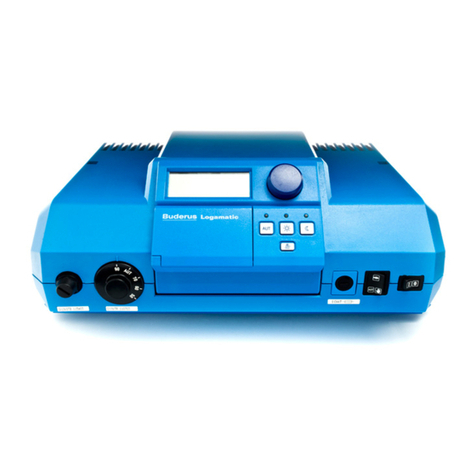
Buderus Ecomatic HS 2105 User manual

Service Manual
Ecomatic HS 2105
Save These Instructions !
5647 488 5/98 USA

1
TABLE OF CONTENTS
Introduction 3-4
Mounting Instructions 5-6
Testing the Manual Reset High Limit (STB) 7
Key Code 8
Program Overview and Description of the Installation Level
Entry Process 9-10
Installation Entries 11-30
Display of Heating Curve(s) 31
Testing of Relays 32
LCDTest 33
Total System Reset 34
Version Number 35
Trouble Shooting Procedures 36
Parameter Settings at the Installation Level 37
Sensor Curves 38-39
Wiring Diagrams 40-46
1
2
3
4
5
6
7
8
9
10
11
12
13
14
15

Introduction 1
Brief Description of Control Operation
TheHS2105isaheatingsystemcontrollerintegratingthe
functionsofspaceheatingonoutdoorresetusinganoutdoor
sensor,priority domestichotwaterheating (DHW) ofan
indirectfiredwaterheater,periodicoperationofaDHW
recirculationpump as well as offeringprogrammablenight
setbackfor customizedoperation.Optionalmodules provide
2-stageor dual burner control andoutdoorresetcontrolofa
motorizedmixing valve for floor heatingapplications.
Note:Buderus HydronicSystems,Inc.strongly
recommendsthe use of a thermostaticvalveonthe
outletof the DHW storage tanktopreventscalding
whenoperating the HS2105 in manualoverride mode.
Two different controlmethodscanbe utilized withrespectto
spaceheating. Parameterslistedin boldareseton thecontrol.
Referto relevant sections in thismanualformoredetails.
Case1: All heatingzones are controlledby on/off
thermostats.
Thespace heating operates along aheatingcurve;
figure1 showsatypical curve.Theslopeisset bythe
“REF TEMP” value;the heating curvecanbeshifted
upor down with the“OFFSET”.The boiler maintains
temperaturewithin thedashedlinesof the burner
differential.Thecontrolusesthedifferencebetweenthe
specified“DAY TEMP” and“NIGHT TEMP” values
tocompute a lowerheatingcurvefornight mode operation.
OnacallforDHW,thecontrolcanfiretheburnerup
tothe “MAX TEMP 1” settingfor maximum recovery.
Thecontrol temporarily interrupts pump operationwith
theburner running when the boilerwatertemperature
dropsbelow the “PUMPLOGIC” settingforcondensation
protection.
3
Fig. 1: Typical heating curves for the HS2105 without a room sensor
MAX TEMP1 Heating Curve
(day mode)
Heating Curve
(night mode)
Burner
Differential
Pump Logic
Offset
200
180
160
140
120
100
80
60
RefTemp
70 60 50 40 30 20 14 10 0 -10 -20 -30
OUTSIDETEMPERATURE (˚F)
2

Mounting Instructions 2
5
• Removethe front panel oftheboiler.
• OnlynecessarywiththeG124X, G224E, G234X and G334X
boilers.
• Removethe two screwsandhousingfromthetop of the
Ecomatic.
• Insertthe two frontfeetofthecontrol into theholesprovided
onthe top of the boiler.Then,firmlypush downontherear of
thecontrol until it snaps intoplace.
•Thesensor bundle consists of onethermistor(FK),two
capillariesand aspacer.Mount thesensorsper thefollowing
boilerspecific instructions. Thechromewellis supplied with
the Ecomatic.
G115, G205, G305: Replace brasswellwithchrome Ecomaticwell.
Thesensor bundle must be fullyinsertedintotheEcomaticwell.
G124X: Unwrap the sensor bundle. Removespacers fromthechrome
wellontheboiler.Removethecoppersleeve from oneofthecapilaries.
Installall 3probesinwith the Honeywellcapillary.
G224E/G234X/G334X: Thetridicator assembly should be movedto
thesupply piping and replaced withthechromeplatedEcomaticwell.
Thesensorbundlemustbeinsertedintothiswell.
• Fastenthe controltotheboiler jacketusingthetwo screwsas
shown.
1 Introduction
4
Case2: Multiple zoneswith the mainzone on
constant circulation
Theheating curveis setinasimilarwayas in Case 1. A
roomsensor is required in theconstantcirculationzoneto
provideroom temperature compensation for fine-tuningof
theheating curve.Themain zonesetsthewatertemperature
availableto allsecondaryzones.Specified day andnight
temperatureson the room sensor areusedinternallyto
computea heating curveduringnightmode.
Case3 : Multiple Temperatures
Theheating curvefor thehightemperaturezone(s)
isset on CIRCUIT1.CIRCUIT2 definesthelow
temperatureheating curveusingamotorizedmixingvalve.
TheHS2105 controlpositionsthemixing valve based
onthe outside andsupplytemperaturemeasured byastrap-on
sensor.Eachheatingcircuit canbeequippedwithanoptional
room sensor.
Fig.2:HS2105heating curvewithroom sensoradjustment
Fig.3:Highandlow temperatureheatingcurves; requiresmodule FM241
MAX TEMP1 Heating Curve
(day mode)
Heating Curve
(night mode)
Burner
Differential
Pump Logic
Offset
200
180
160
140
120
100
80
60
RefTemp
70 60 50 40 30 20 14 10 0 -10 -20 -30
OUTSIDETEMPERATURE (˚F)
Room Sensor
Compensation Effect
Room Sensor
Compensation Effect
MAX TEMP1
Heating Curve Circuit 2
(day mode)
Heating Curve Circuit 2
(night mode)
Heating Curve Circuit 1
(night mode)
Heating Curve Circuit 1
(day mode)
Burner
Differential
Pump Logic
MaxTemp2
Offset
200
180
160
140
120
100
80
60
RefTemp
RefTemp
70 60 50 40 30 20 14 10 0 -10 -20 -30
OUTSIDETEMPERATURE (˚F)

1. Switchthe control on
withthe main power
switch(IPosition).
2. Enterthe key code
(Seepage 8).
3. Turn the dial until “RELAYS”appearsinthedisplay.
4. Press and hold the button.Turnthe dial until
the displayshows “BURNER ON”.Theburnerstarts.
Heatingpumpswillnotrunduringtheburnertest.
Allowthe burner torununtilburner shuts offatthe
setpointon the aquastat dial.
5. Removethe black aquastat dial.
6. Push the green button inwithscrewdriverorsimilar
instrumentto bypasstheadjustableboiler aquastat.
Holdthe green button until theSTBormanualreset
highlimittrips.This happensatapproximately 230°F.
7. Runcirculatorstoremoveexcessheat.Then,to reset
theSTB,removethe safety nut.Pressinthereset
buttonunderneath.Thiswillreturnthecontrolback
tonormal operation.
ToResumeNormalOperation:
PresstheAUTbutton.
Testing the Manual Reset High Limit (STB) 3
BURNER ON
Aquastat Dial
Green Button
Safety Nut
180
7
RELAYS
oF
70
oF
70
2 Mounting Instructions
6
• Electricalconnections must bemadeaccordingto the wiring
diagram(See pages 40-46).
• Allthe wires should be routedthroughthecableracewayat the
rearof theboiler.Rearpanel jacketmaybemodified perlocal
code.Route the wiresontopofthe insulation tothebackof the
control.
• Usethe white strain reliefs providedtolockall cables into place
onthe back of the control.
• Replacethe top housingofthecontrol and fastenthetwo screws.
Thecontrol isreadytobe placed intooperation.
• Tiltthe display to the desiredposition.

Movingaround theMainMenus
•Thekey codeallowsaccessto the mainmenus.
• Toaccessdifferentmenus,turnthedial.
• Toaccessasubmenu,pressandreleasethe buttonfrom
themainmenu.
• Tomoveaboutthatspecificsubmenuandreviewthespecific
entries,turnthedial.Eachentryinthatspecificsubmenu
appearsnowinthedisplayasthedialisturned.
• Tochangethevalueofaspecificentryinthe submenu,firstget
thatentryinthedisplaybyturningthedial,thenpushand
holdthe button.Thedisplayshowsthespecificentry
blinkingwithitscurrentvalue.Turnthedialtoselectthe
desiredvalue.Releasethe button.Thiswillsavethenew
value.
• Tomovetothenextentryinthisspecificsubmenu,turnthedial.
• To movebackto themainmenu,pressand releasetheRETURN
button.
• Toreturntothestandarddisplay,pressandreleasetheAUTbutton.
Note:TheHS2105controlautomaticallygoesbacktothestandarddisplayif
noentriesaremadewithinfiveminutes.
Program Overview 5
+
+
AMERICAN
PERIM-HTG
PERIM -HTG
REF TEMP
REMOTE 1
BLR TEMP
CIRCUIT1
CIRCUIT1
CIRCUIT1
TheInstallation level consists of amaximumof12mainmenus. Each main menu addressesaspecificsetoffeatures
ofa certaincomponentof theheatingsystem.These featuresarecontained insubmenus.Mostvaluesarechangedatthe
submenulevel,notatthemainmenulevel.
Notice:Anumberofentrieswillonlyappearwhentheircorrespondingmodulesareinsertedinthecontrol.
Thesemodulesandtheirfunctionsare:
ModuleFM241: Mixingvalvecontrolmodule.
ModuleFM242: Two stagefiringcontrolmodule.
ModuleKM271: Communicationsmodule.CurrentlynotavailableintheU.S.A.
Whenanyofthesemodulesareinstalled,theHS2105control automaticallyrecognizesthemandreleasesaccesstothe
correspondingmenus,submenusandtheirentries.
9
Key Code
Theaccess to the installation leveloftheHS2105control
isprotected against unauthorized use byaspecialkey
code.Entry in this level allowsyoutochangesettings
describedin this manual.
Thisinstallation level should only beaccessedbyaheating
contractororatrained operator.Entriesatthislevel
identifyto the control the differentcomponentsofthe
heatingsystem, specify how these componentsaretobe
operatedand set up the properheatingcurve(s).These
entriesin generaldonotrequire any adjustment.Any
adjustmentsmust be performed by aheatingcontractor
ora trained operator.
4 Key Code
KeyCodeAccess Procedure for access to the
Installation Level
• Pressand hold the lowerlefthandENTER
button.
• Inserta pointed object into theholedirectly
tothe right of the ENTER button.
• Releaseboth buttons.Thedisplayreads
“DEUTSCH”(GERMAN).
DEUTSCH
To change the language selection:
•Enterthekeycode.Theword“DEUTSCH”
(GERMAN)appears inthe display.
• Pressand holdthe button.
•Turnthedialtoselectthe“AMERICAN”
language selection.
Returnedto the Standard Display:
• PresstheAUTbutton.
Note:The controlresumesautomatic operationifno
entriesare madeforaperiod of 5minutes.
8
AMERICAN

▲
11
Freeze Protection: “FREEZTEMP”
Toprevent the heating systemfromfreezing,the control willautomatically
permitthe heating circulators to runcontinuouslyinthenightmode when
theoutside temperaturedropsbelowthe “FREEZTEMP” valueirrespective
ofthe selected setback mode.
Thefactorysettingis41˚F;the range is 0˚F to 50˚F.
To change the FREEZTEMP:
• Enterthe key code.
• Turn thedialuntil theword“BLR TEMP”appearsinthedisplay.
• Pressthe button and release.
Thedisplaywillshow“FREEZTEMP”.
• Pressand hold the button.
Thecurrent valueofthe“FREEZTEMP” isblinking.
• Turn the dial until thedesired“FREEZTEMP”valueappearsin the display.
Returnto the mainmenu:
• Pressthe return.
RETURN TO THE STANDARDDISPLAY:
• PresstheAUTbutton.
Note: Thecontrolresumesautomatic operationifnoentries aremadefora
periodof five minutes.
Note 1: The“FREEZTEMP”settingisthe determiningvaluewhenusing
the“OASETBACK”setbackmode.Thecirculatorswillnotoperateinnight
modewhen theoutsidetemperature exceedsthe“FREEZTEMP” value.The
circulatorswill run constantly for outsidetemperaturesbelowthe
“FREEZTEMP” value.
Note2: The“FREEZTEMP”settingis alsoofsignificancein termsof
pumpoperation duringthenightmode whenusingroom sensors.Theheating
circulators(on circuits 1 and 2)willstopwhentheactual room temperature
exceedsthe desirednighttemperature ANDtheoutside temperatureexceeds
the“FREEZTEMP” value.
Installation Entries 6
BLR TEMP
FREEZTEMP ˚F
40
❅
FreezeProtection:“FREEZTEMP” 0˚Fto50˚F 41˚F
Range Factory Setting Current Setting
BURNER
BURNER2*1),MODBNR*2
HTG1 PUMP
HTG2 PUMP
MIXVALVE*5)
DHW PUMP*6)
RECIRPUMP*6)
10
5 Program Overview
ListingofEntries at theInstallation Level
Accessto the installation is doneusingthekeycode.
Display Read-out +
DEUTSCH Language selection
BLR TEMP
CIRCUIT1
CIRCUIT2
Boiler parameters
HeatingZone1InstallationParameters(unmixedzone)
HeatingZone2InstallationParameters(mixedzone)*5
Frost protection temperature
Buildingheatstoragecapacity
Burner operation details
Minimumfiringrateforamodulatingburner*2
Modulationtimeforfullmodburner*2
WatertemperaturesettingforPumplogic
Maximumelectronichighlimitforboilertemperature
Fluegaswarningtemperature*3
Identifiesnatureofhightempzone(baseboard,radiatorsetc.)
ReferenceTemperatureforspecifyingboilerzoneresetcurve
Roomsensorpresentforunmixedzoneyes/no
Room temperature compensation*4
Setback mode selection
Offset,verticalshiftofresetcurve
Identifiesnatureoflowtemperaturemixedzone
ReferenceTemperatureforspecifyingboilerzoneresetcurve
DHW priorityonmixedzone*6
Maximumelectronichighlimitformixedzone
Roomsensorpresentformixedzoneyes/no
Room temperature compensation*4
Setback mode selection
Offset,verticalshiftofresetcurve
Domestichotwateryes/no
DHW recirculation pump
Heatingcurveforunmixedzone
Heatingcurveformixedzone
Burner Relay
Burner2Relay*1),Modulationhigher/lower*2)
Boilerzonepump(unmixedheatingcircuit)
Mixedzonepump(mixedheatingcircuit)
Mixing valve open/close*5)
Tank charging pump*6)
DHW recirculation pump*6)
LCD test
Generalsystemresettofactorysettings
Control version number
PERIM-HTG
REF TEMP
REMOTE 1
ROOM COMP*4
OASETBACK
OFFSET
FREEZTEMP
BLDG RESP
TWO STAGE*1
MIN MOD*2
MOD TIME*2
PUMPLOGIC
MAX TEMP1
FLUE TEMP*3
FLOOR-HTG
REF TEMP
DHWPRIOR
MAX TEMP2
REMOTE 2
ROOM COMP*4
OASETBACK
OFFSET
RELAYS
LCD- TEST
RESET
VERSION
DHWPROD
RECIRPUMP
HTGCURVE 1
HTGCURVE 2
Relaytestondifferentsystemcomponents
*1 AppliesonlywithmoduleFM242installedand2stageburnerselected.
*2 AppliesonlywithmoduleFM242installedandmodulatingburnerselected.
*3 AppliesonlywithmoduleKM271.
*4 Appliesonlywithremotesensorinstalled.
*5 AppliesonlywithModuleFM241installed.
*6 Appliesonlywithdomestichotwaterinstalled.
Page
8
9
11
12
13
14
15
16
17
18
19
19
20-21
25
26
27-28
22
19
19
20-21
23
24
25
26
27-28
22
29
30
31
31
32
33
34
35

BurnerSystemwithoutFM242module 1-stage
BurnerInstallation:“BURNER”
Theburner module FM242 must beinstalledforthissubmenuto appear.
ThefactorysettingwithouttheFM242moduleis“ONE STAGE”.
However,this settingdoesnot becomevisibleinthe displaywhenmodule
FM242is not installed.
TheHS2105controlautomaticallyswitchesfrom single stage to two stage
whenthe FM242 module is inserted.Onecanselectatthis point between a
onestage burner,twostageburner (ordualboiler/burner system)or
modulating burner.
Note:In case a two stageburner(ordualboilersystem) is
selected,separateburnerruntimeswillbedisplayed.
To change the “BURNER” setting:
•Enter thekey code.
•Turnthe dial untiltheword“BLR TEMP” appearsinthedisplay.
• Pressthe button and release.
Thedisplaywillshow “FREEZTEMP”.
•Turnthedialuntiltheword“TWO STAGE”appearsinthedisplay.
• Press and holdthe button.
Theadjustable parameter is blinking.
•Turnthe dial until the word“MODBRNR”appearsinthe
displayfor a modulating burner.
Returnto mainmenu:
• Pressthe button.
RETURN TO THE STANDARD DISPLAY
•PresstheAUTbutton.
Installation Entries 6
13
BLR TEMP
TWO STAGE
MOD BRNR
BurnerSystemwithFM242module 1-stage/2-stage/modulating 2-stage
Range FactorySetting CurrentSetting
6 Installation Entries
Building Type: “BLDG RESP”
Thetypeofbuildingintermsofinsulatingfactor,heatstoringcapacity
andresponse to outside temperature changesisspecifiedwiththe
“BLDG RESP” setting.
TheHS2105 control usesthissettingto respond inadelayedfashion
tochanges in outsidetemperatureandrelieson the heatstoringcapacityto
maintaina comfortabletemperaturelevel inthebuilding.The settingsare
defined as:
1=Buildings with smallheatstoringcapacity and mediumlevelsof
insulation (Wood constructionandmediumtoheavyinsulation).
2=Buildings with mediumheatstoringcapacityand high levelsof
insulation(Brickconstructionwithmediuminsulation).
3=Buildings with highheatstoringcapacity and highlevelsof
insulation(Heavy brick construction with goodinsulation).
Note:Forareaswhererapidchangesinoutsidetemperaturesoccur,
itis recommended toalwaysusesetting1 irrespective ofthetypeof
construction.
To change the “BLDG RESP”setting:
• Enterthe key code.
• Turnthedialuntiltheword“BLRTEMP” appears inthedisplay.
• Press the buttonandrelease.The display willshow“FREEZTEMP”.
• Turnthedialuntiltheword“BLDG RESP”appearsinthedisplay.
• Pressandholdthe button.
Thecurrentvalueof the“BLDG RESP”settingisblinking.
• Turnthedialuntilthedesired“BLDG RESP”valueappearsinthedisplay.
Returntomainmenu:
• Pressthe button.
RETURN TO THE STANDARD DISPLAY
• PresstheAUTbutton.
Range Factory Setting Current Setting
BLR TEMP
BLDG RESP 2
12FreezeProtection:“FREEZTEMP” 1,2,3 2

Modulating Valve Operating Timefor the Modulating Burner:
“MOD TIME”
Theinstallation of the burner moduleFM242andtheselectionof a
modulatingburner (“MOD BRNR”)arerequiredinorderforthissubmenu
to appear.The modulatingvalveoperatingtimeisthe total time in seconds
requiredfor the modulatingburnertogo through itsfulloperatingrange.
Thefactorysettingis12seconds.
To change the “MOD TIME” setting:
•Enter the key code.
•Turn thedialuntil theword“BLR TEMP”appearsinthedisplay.
• Pressthe button and release.
Thedisplaywillshow“FREEZTEMP”.
•Turnthedialuntiltheword“MOD TIME”appearsinthedisplay.
• Press and holdthe button.
Thecurrent valueoftheadjustable parameter isblinking.
•Turn the dial until thedesiredvalveoperatingtime
“MODTIME”appearsinthedisplay.
Returntomain menu:
• Pressthe button.
RETURN TO THE STANDARD DISPLAY
•PresstheAUTbutton.
Installation Entries 6
MOD TIME 12
15
MOD TIME
ValveOperatingTime “MODTIME” 5sec-60sec 12sec
Range Factory Setting Current Setting
1514
MinimumFiring Ratefor aModulatingB urner:“MIN MOD”
Theinstallation of the burner moduleFM242andtheselectionof a
modulatingburner (“MODBRNR”)are requiredinorder forthis
submenuto appear.The minimumfiringrateoftheburner modulation
isspecified in this setting.
Thefactory setting is 30%.
To change the “MIN MOD” setting:
• Enterthe key code.
• Turn thedialuntilthe word“BLR TEMP”appearsinthedisplay.
• Press the button andrelease.
Thedisplaywillshow“FREEZTEMP”.
• Turnthedialuntiltheword“MINMOD”appearsinthedisplay.
• Press and hold the button.
Thecurrent valueofthe“MIN MOD” isblinking.
• Turn thedialuntil thedesired“MIN MOD” value appearsin
the display.
Returnto mainmenu:
• Pressthe button.
RETURN TO THE STANDARD DISPLAY
• PresstheAUTbutton.
6 Installation Entries
MIN MOD
MIN MOD
MinimumModulation“MIN MOD” 10%to60% 30%
Range Factory Setting Current Setting
30
40

MAX TEMP1 176
˚F
MAX TEMP1 193
˚F
MaximumBurner Shut-off Temperature:“MAX TEMP1”
Amaximum temperatureisspecified abovewhichtheelectronicboilersensor
shutsoff the burner.Thissettingisnotoperativewhen the control is operatingin
themanual mode using the emergencyoverrideswitch.Theadjustablecapillary
highlimit shuts off the burnerinmanualoverride mode.
Thefactorysettingis 176˚F.
To change the “MAX TEMP1” setting:
•Enter the key code.
•Turnthe dialuntiltheword “BLR TEMP”appearsinthedisplay.
• Press the buttonandrelease.
Thedisplay will show “FREEZTEMP”.
•Turnthedialuntiltheword“MAX TEMP1”appearsinthedisplay.
• Press and holdthe button.
Thecurrentvalueof“MAXTEMP1”isblinking.
•Turnthe dial until the desiredvaluefor“MAXTEMP1”appearsin
the display.
Return to main menu:
• Press the button.
RETURN TO THE STANDARD DISPLAY
•PresstheAUTbutton.
Installation Entries 6
MaximumBoilerShut-offTemperature 158-210˚F 176˚F
Range Factory Setting Current Setting
17
Thefactory setting is: 104˚F for aonestageburner
113˚Ffor a two stage burner
122˚Ffor a modulating burner
Tochange the “PUMPLOGIC”setting:
•Enter the key code.
•Turn thedialuntil theword“BLR TEMP”appearsinthedisplay.
• Pressthe button and release.
Thedisplaywillshow“FREEZTEMP”.
•Turn the dialuntiltheword “PUMPLOGIC” appearsinthedisplay.
• Pressand hold the button.
Thecurrentvalueof “PUMPLOGIC”isblinking.
•Turn the dialuntilthedesiredvalue for “PUMPLOGIC”appears
inthedisplay.Consultthetable belowforyourboilermodel.
Table1: Minimum“PUMPLOGIC”values
Boiler Series 1-STAGE 2-STAGE MODULATING
G115,G205, G305 104 N/A N/A
G315 122 131 131
G515 122 131 131
G124X 104 N/A N/A
G234X/G334X 104 122 N/A
Note: Theminimumburner shut-offtemperaturealways exceedsthe“PUMPLOGIC” valueby9˚F.
Return to main menu:
• Pressthe button.
RETURN TO THE STANDARD DISPLAY
• Pressthe AUT button.
Note: The controlresumesautomaticoperation ifnoentriesare made foraperiodof fiveminutes.
16
PUMPLOGIC 104
130
PUMPLOGIC
Pump Shut-offTemp.“PUMPLOGIC” 59-140˚F 104˚F
Range Factory Setting Current Setting
˚F
˚F
Condensate ProtectionFeature:“PUMPLOGIC”
TheHS2105 controlhasabuilt in featurecalled“PUMPLOGIC”where thecontrolinterruptscirculator
operationwhentheburner firesintoacoldboiler.Onceaspecifiedtemperatureisreachedin theboiler,the
pumpsare permittedtorun. Thistemperatureis adjustableandset withthe“PUMPLOGIC”setting.
6 Installation Entries

FLUE TEMP OFF
FLUE TEMP 480
˚F
Flue Gas Temperature Sensing: “FLUETEMP ”
ModuleKM271 must be installed forthissubmenutoappear.Thefluegas
temperaturecan only bemeasuredandshownin the displaywhentheKM271
moduleis installedintheHS2105 control.Thefluegas temperaturecanbe
viewed in the display.
Whenan ECOKOM communicationsystemandmodem is installed,aservice
messageis transmittedwhentheflue gastemperatureexceedsa presetvalue.The
boilerwill requiremaintenance.Theflue gassensingcapability mustbeactivated
whenthe KM271 module has beeninstalled.
Thefactory setting is “OFF”.
Tochange the “FLUE TEMP” setting:
• Enterthe key code.
• Turn thedialuntil theword“BLR TEMP”appearsinthedisplay.
• Pressthe button and release.
Thedisplay will show “FREEZTEMP”.
• Turn thedialuntil theword“FLUE TEMP”“OFF” appears in the display.
• Pressand hold the button.
Theadjustable parameter is blinking.
• Turn the dial until thedesired fluegastemperatureisshown in
thedisplay abovewhich a service message would be transmitted.
Return to main menu:
• Pressthe button.
RETURN TO THE STANDARD DISPLAY
• Pressthe AUT button.
Note: Thecontrolresumes automaticoperationif noentriesaremadeforaperiod
of5 minutes.
FlueGasTemperature “FLUETEMP” OFF/120-480˚F OFF
Range Factory Setting Current Setting
6 Installation Entries
18
Circuit1Options:
• “PERIM-HTG” Circuit1 operates on a resetcurve for perimeter heating
suchas baseboard or radiators (Range86˚F-194˚F).
•“NOSYSTEM” Circuit 1followscircuit2reset curve.Thisoption
canonlybeselectedwhenmoduleFM241isinstalled.
Theboileroperates9˚F abovethecircuit2
requirements.
Circuit 2 Options:
•“PERIM-HTG” Circuit2 operates on reset curvefor perimeter heating
(Range 86˚F-194˚F).
• “FLOOR-HTG” Circuit2 operates on a resetcurve suitable for radiantfloor
heating(Range 86˚F-140˚F).
• “NO SYSTEM”Circuit 2 follows the same reset curveasspecifiedfor circuit 1.
To change the heating circuit descriptions:
• Enterthe key code.
• Turn thedialuntil theword“CIRCUIT 1”or“CIRCUIT 2”appears
inthe display.
• Pressthe buttonand release. Thedisplaywillshow“PERIM-HTG”.
• Pressand hold the button.Theadjustableparameter is blinking.
• Turn the dialuntilthedesiredheating circuit descriptionappearsinthe
display.
Returntomain menu:
• Pressthe button.
RETURN TO THE STANDARD DISPLAY
• PresstheAUTbutton.
PERIM-HTG
NO SYSTEM
FLOOR-HTG
PERIM-HTG
NO SYSTEM
CIRCUIT1 PERIM-HTG/NO SYSTEM PERIM-HTG
CIRCUIT2 PERIM-HTG/FLOOR-HTG/NO SYSTEM FLOOR-HTG
Range FactorySetting CurrentSetting
CIRCUIT1
CIRCUIT2
Heating System Lay-out
TheHS2105 controlisdesignedforindividual controloftwoheating circuits withdifferentwatertemperatures. The
secondheating circuit isonlypossiblewhen the mixingmoduleFM241has beeninstalled.Thenatureof eachheating
circuitmust be specifiedtothecontrol. For example,baseboardheatingon circuit 1andradiantfloor heating oncircuit2.
TheHS2105 control needs this informationtosetthepropercurvaturefor the different heating curves.
Installation Entries 6
Note:In case module FM241 isinstalled,repeatthe“Turnthedial”stepuntilthe word“CIRCUIT 2”appears inthedisplay.
Repeatthe steps abovetoproperlydefinecircuit2.
19

Heating CurveSelection: Setting the“REF TEMP”
The “REFTEMP” setting isadjustablefrom 86˚Fto194˚F.Theslope
ofthe heating curvechangesasthe“REF TEMP”valueischanged.
Thefactory setting is 167˚F for“PERIM-HTG”circuitsand113˚Ffor
“FLOOR-HTG”circuits.
To change the “REF TEMP” settings
• Enterthe key code.
• Turn thedialuntiltheword “CIRCUIT1”or“CIRCUIT2” appears
inthe display.
• Pressthe button and release.
Thedisplaywillshow“PERIM-HTG”or“FLOOR-HTG”.
• Turn thedialuntil theword“REF TEMP”appears in the display.
• Pressand hold the button.
Thecurrentvaluefor“REFTEMP”isblinking.
• Turn thedialuntil thedesiredvalue for“REFTEMP” appearsin
the display.
Returntomain menu:
• Pressthe button.
RETURN TO THE STANDARD DISPLAY
• PresstheAUTbutton.
• Repeat aboveprocedurefor“CIRCUIT 2”ifmodule FM241isinstalled.
21
“REF TEMP”for“PERIM-HTG” 86˚F-194˚F 167˚F
“REFTEMP”for“FLOOR-HTG” 86˚F-140˚F 113˚F
Range FactorySetting Current Setting
167
˚F
140
˚F
REF TEMP
REF TEMP
Installation Entries 6
Note:The controlresumesautomaticoperation if noentriesaremade foraperiodof 5 minutes.
Note:Incasethemaximumdesigntemperaturefortheradiantfloorsystemexceeds140˚F,youmustselect
“PERIM-HTG”for circuit2to reachsufficientlyhigh watertemperatures.
20
REF TEMP ˚F
167
Heating CurveSelection:SettingtheReference Temperature
Theheating curveestablishes therelationshipbetweentheoutside
airand boilerwatertemperatures. Theboilerwateris automatically
loweredatwarmeroutsidetemperatures and raised at colder outside
temperatures.
Thecorrect heating curveisdeterminedbythecharacteristics of the
house(i.e., type of radiation, degreeofinsulation,heatingsystem
designtemperatures, etc.)Baseboardsystemsare generally designed
tooperate at 190˚F on designday.The figurebelowshowsa numberof
heating curvesfor differentdesigntemperatures.
68 59 50
OUTSIDETEMPERATURE(°F)
41 32 23 14 5
0 -10 -20 -30 -40
-4 -13 -22 -31 -40
167
158
140
122
104
86
68
194
176
BOILER
WATER
TEMPERATURE(°F)
6 Installation Entries
Example: “REF TEMP” Selection:
Assumea panel radiator is designedwitha
maximumwater temperatureof176˚Ffor a
-20˚Fdesignday.Locatethepointwhere176˚F
watertemperature intersects -20˚F outside
temperature.Draw a curvefromthispointto the
startingpoint (68˚). Nowenter the chart at the 14˚F
pointand movevertically until you intersectyour
curve. Now movehorizontally
tothelefttofindyour“REF TEMP”.Inthis caseit
wouldbe approximately 142˚F.
Toselectthe proper curve,onemustalways specify the desired watertemperatureforanoutsidetemperature of 14˚F.The
correspondingwater temperatureisthe “REF TEMP”setting.The HS2105controlthenautomatically
createsa curve foralloutsidetemperatures.
Heating Curve Adjustments
The “REFTEMP” fineadjustmentshouldbedone basedoncoldweatherperformance. Increasethe“REF TEMP”valueifthe
roomtemperatureistoolowduringcoldweather.Decreasethe“REF TEMP”settingifoverheatingtendstooccur.Makeonly
minoradjustments and allow ample timeforthesystemtorespond.
Table of contents
Other Buderus Control System manuals
Popular Control System manuals by other brands

NuAire
NuAire Smart S Installation and Maintenance

DoorKing
DoorKing 2112 Installation & owner's manual

Sky Elevator
Sky Elevator Sky 301-VS Troubleshooting

TECALEMIT
TECALEMIT HDA eco operating manual

Naish
Naish Torque 2 + i3 55 user manual

GRASL
GRASL RWZ 5 f Assembly, installation and operation instructions

Bend-Tech
Bend-Tech Dragon A400 Assembly manual

Toshiba
Toshiba TOSDIC-CIE DS instruction manual

Mitsubishi Electric
Mitsubishi Electric MELDAS C6 Parameter manual

ITW
ITW SIMCO ION IQ Power HLC Installation and operating instructions

Raven
Raven SCS-330 Installation & service manual

DriSteem
DriSteem Vapor-logic 4 Installation and operation manual