TFA1-298 7
Premise
Before proceeding with the installation, read this manual thoroughly. It contains important references and instructions concerning
the correct installation, operation and servicing of the fire alarm system.
Operational restrictions and purposes of a fire alarm system
It is fundamental to consider that a fire alarm system does not guarantee protection and immunity against material damages, of any
kind and nature, caused or induced by fire. It is equally important that the fire alarm system must be installed and kept in a state of
perfect functioning according to the instructions provided by the manufacturer.
The Tecnofire systems, designed for the detection, extinguishing, actuation, evacuation etc., are able to notify fire alarms promptly
to the final user and/or the personnel in charge. The systems process the events automatically and, according to programming,
transmit acoustic and/or telematic notifications apt to urge the evacuation of the premises, activate automatic control or
extinguishing systems and eliminate all situations and events that may feed the fire, with the aim of guaranteeing the safety of the
persons and safeguarding the property.
Installation requirements
Although this manual contains all the necessary procedures for a correct installation of the equipment, the interpretation and
correct application of its contents requires adequate training of the technical staff in charge of the installation. In particular,
the installer must have the necessary technical skills and acquaint himself with the valid European standards regarding both
the general requirements for fire alarm systems and the specific provisions for installation, electrical safety and maintenance.
In addition, he must have a thorough knowledge of the products, acquired through specific training at Tecnofire
(division of Tecnoalarm S.r.l.).
Environmental requirements
The control panel and all the system components must be installed inside structures or buildings with climatic characteristics
(temperature and non-condensing relative humidity) that comply with the standards applied during certification. Specific operating
temperature and humidity values are indicated in the relevant technical data tables.
Usage requirements
To avoid damage to the equipment or, even worse, dangerous malfunctions in detecting fire and actuating the devices and systems
that operationally dependent from the fire alarm system, it is mandatory to use only the components and devices indicated by
Tecnofire. The interfacing with third-party systems must be made with Tecnofire input and output modules, verifying each time the
full compatibility. If in doubt, always refer to the Tecnofire technical support service.
Technical support
The technical support service of Tecnofire provides assistance in answering technical questions regarding the installation,
functioning and operation of the Tecnofire products.
Power supply
In the planning phase, to ensure the autonomy of service requested by the standards, it is important to size the primary (mains
power) and secondary (battery) power supply correctly.
It must be considered that, in case of power failure, the system ensures functioning by means of batteries for a limited period of
time, the length of which depends on the capacity and the state of efficiency of the batteries.
Induced damage
Prior to working on any system component, in order not to cause damage while installing or servicing the equipment, always
disconnect both the primary (mains power) and secondary (battery) power supply of the system. To avoid damage caused by
electrostatic discharges, handle the electronic boards of the devices with care and avoid direct contact with the electronic components.
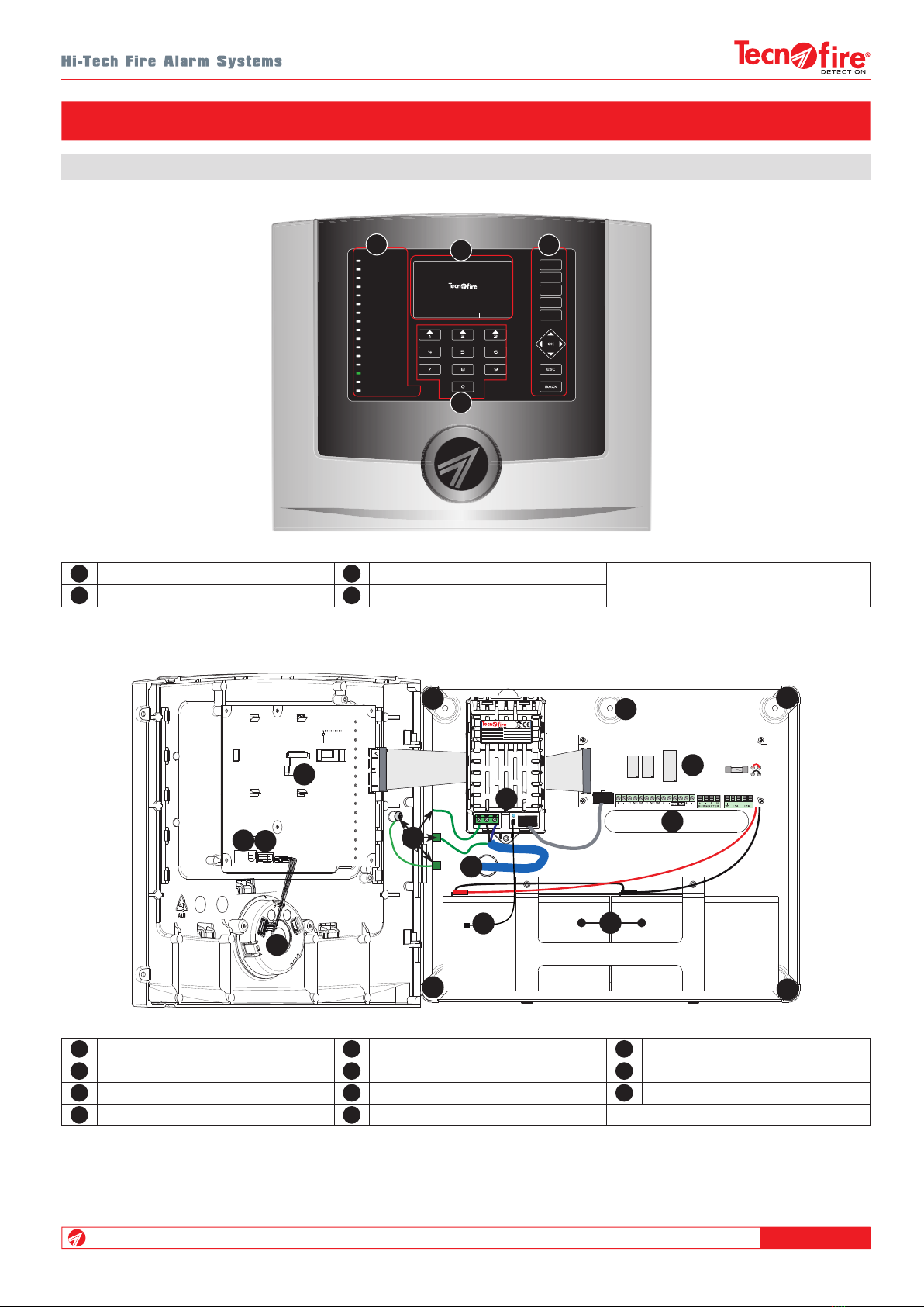
1 - GENERAL REFERENCES