5Bosch | 11/04 | 48176D
D7030X-S8 | Installation Guide | 7.0 Programming
1
2
3
4
5
6
7
8
POWER
ON
SYSTEM
TROUBLE
FIRE SYSTEM
ANNUNCIATOR
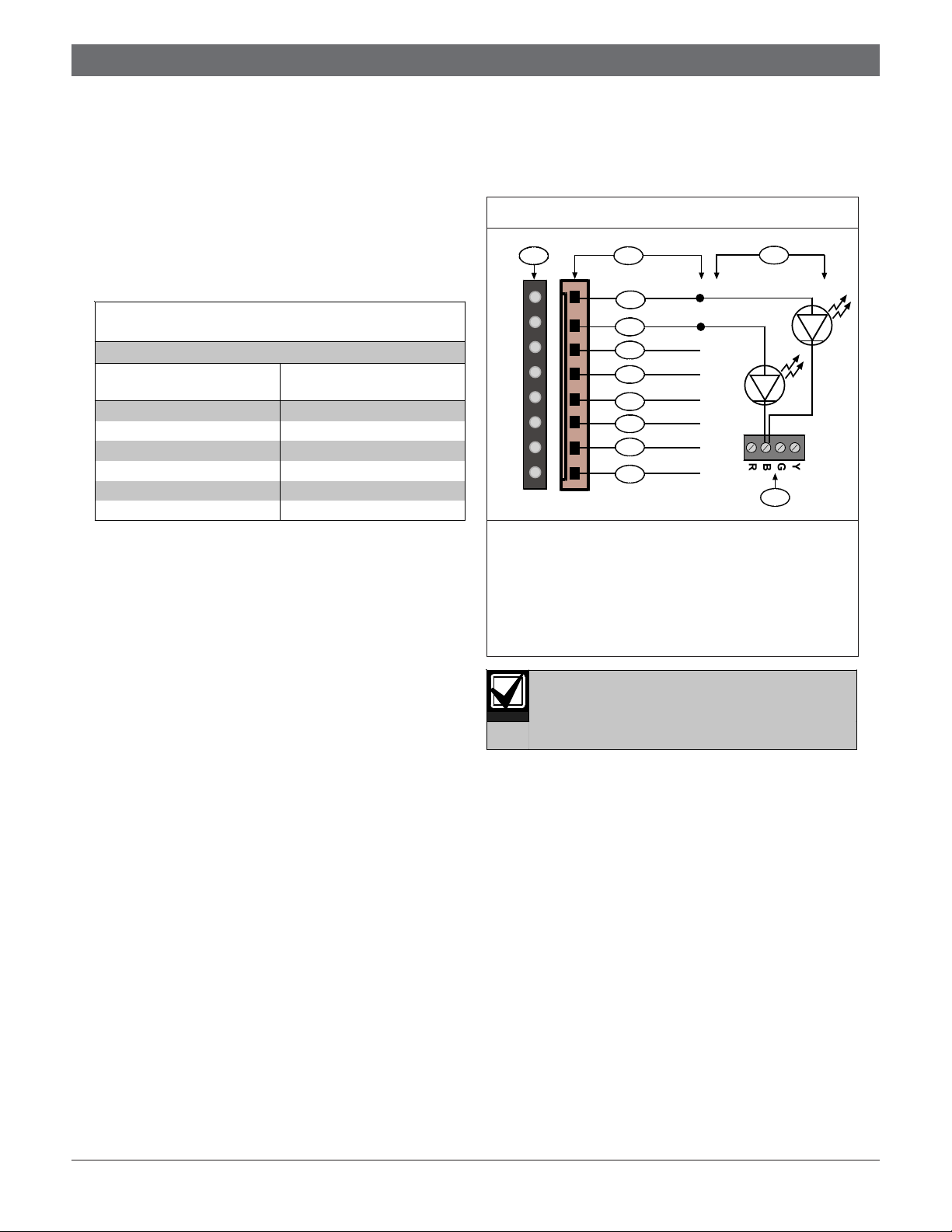
TOP
FIRST
FLOOR
SECOND
FLOOR
THIRD
FLOOR
FOURTH
FLOOR
TOP
BASEMENT
GYM ONE
GYM TWO
STORAGE
AREA
1 - Zone 1 5 - Zone 5
2 - Zone 2 6 - Zone 6
3 - Zone 3 7 - Zone 7
4 - Zone 4 8 - Zone 8
Note: All eight zone LEDs are yellow.
Figure 6: Zone Label Location
6.0 Mounting
Mount the D7030X-S-8 in easily seen
positions at entry locations.
1. Before mounting the D7030X-S8 in a standard
three-gang box, mark the zone labels and insert
them into their respective slots (Figure 6).
2. Set the annunciator in or over the three-gang box.
3. Position the faceplate.
4. Secure the D7030X-S8 to the box using the screws
(supplied).
5. Connect the standby batteries.
6. Close the 120 VAC dedicated breaker controlling
the power input to the control panel.
7.0 Programming
Program the D7030X-S8 by installing
firmware version 2.0 or greater in the FACP.
You can assign program zones to light whenever points
within that zone go into alarm. Do this by assigning an
output zone to each D7030X-S8 input point. For
example, if you assign Output Zone 1 to Input Points 1
through 5, the LED for Output Zone 1 lights when any
input point in this zone goes into an alarm.
1. Press [0/PROG] to enter the Programming Mode.
PROG MODES appears across the top line and the
Programming Menu options scroll across the second
line.
2. Enter a personal identification number (PIN) if a
prompt appears for this information.
3. At the Programming Menu, press [3] for Prog
System.
4. Press [4] for Option Bus.
5. With the D7030X-S8 connected to the option bus,
press [1] for Update Bus.
The FACP indicates a device is added to the option
bus.
6. Press [*/CLEAR] to return to the Programming
Menu.
7. At the Programming Menu, press [4] for Prog
Inputs.
8. Press [1] for Point Number and enter the point
number you want programmed.
9. Press [#/CMND] to accept the entry.
10. Program any supervisory inputs you have to each
zone LED.
11. Press [2] for Output Zone and enter the output zone
for this point.
12. Repeat Steps 6 and 7until all points are
programmed.
13. Press [*/CLEAR] three times to exit the
Programming Menu and return to the Main Menu.