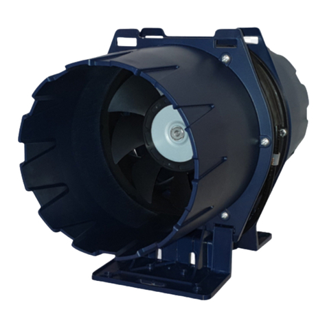
Tecnoclima DST Series Manual

Pag.
1
DESTRATIFICATORE D’ARIA
AIR DESTRATIFIER
SERIE DST
INFORMAZIONI TECNICHE
ISTRUZIONI DI MONTAGGIO USO E MANUTENZIONE
TECHNICAL INFORMATION
ASSEMBLY, USE AND MAINTENANCE INSTRUCTIONS

Pag.
2
Gentile Cliente,
La ringraziamo per aver preferito un
DESTRATIFICATORE D’ARIA serie DST, un
prodotto innovativo, moderno, di qualità e ad alto
rendimento che Le assicurerà benessere, massima
silenziosità e sicurezza per lungo tempo; in modo
particolare, se l’apparecchio sarà affidato ad un
Servizio Tecnico di Assistenza TECNOCLIMA che è
specificatamente preparato ed addestrato per
mantenerlo al massimo livello di efficienza, con minori
costi di esercizio e che, in caso di necessità, dispone di
ricambi originali
Questo libretto di istruzione contiene importanti
indicazioni e suggerimenti che devono essere osservati
per una più semplice installazione ed il migliore uso
possibile del DESTRATIFICATORE D’ARIA serie
DST.
Rinnovati ringraziamenti.
Tecnoclima S.p.A.
Dear Customer,
Thank you for choosing an AIR DESTRATIFICATOR
series DST, an innovative modern with high quality and
efficiency product, which provides comfort, maximum
silence, and safety for a long time; in particular, if the
heater is serviced by one of TECNOCLIMA’s After-
Sales Service Centers, which are specifically qualified
and trained to keep it at its maximum efficiency level,
with reduced operating costs, and, when needed, they
can also provide original spare parts
This instruction manual contains important instructions
and suggestions for simple installation and making the
best use of the AIR DESTRATIFICATOR series DST
Thank you, once again
Tecnoclima S.p.A.
INFORMAZIONI
GENERALI
CONFORMITA’
GENERAL
INFORMATION
CONFORMITY
Il DESTRATIFICATORE D’ARIA serie DST, è
conforme a:
Direttiva Macchine 2 6/42/CEE.
Direttiva Bassa Tensione 2 14/35/CEE.
Direttiva Compatibilità Elettromagnetica
2 14/3 /UE.
The AIR DESTRATIFICATOR series DST
complies with:
Machinery Directive 200 /42/EEC.
Low Voltage Directive 2014/35/EEC.
Electromagnetic Compatibility Directive
2014/30/EU.
INFORMAZIONI
GENERALI
GAMMA
GENERAL
INFORMATION
RANGE
CODICE MODELLO
CODE MODEL
3JEXOI055 DST 55
3JEXOI105 DST 105

Pag.
3
INFORMAZIONI
GENERALI
GARANZIA
GENERAL
INFORMATION
WARRANTY
Il destratificatore d’aria serie DST, gode di una
GARANZIA SPECIFICA che decorre dalla data di
acquisto dell’apparecchio che l’utente è tenuto a
documentare; nel caso non sia in grado di farlo, la
garanzia decorrerà dalla data di fabbricazione
dell’apparecchio. Le condizioni di garanzia sono
dettagliatamente specificate nel CERTIFICATO DI
GARANZIA, fornito con l’apparecchio, che Le
suggeriamo di leggere con attenzione.
The air destratifier
series DST appliance has a
SPECIFIC WARRANTY that begins on the date of
purchase of the unit: the customer must retain
documents as proof of purchase. If the customer
is unable to provide such proof the Warranty
period shall begin as from the date of production
of the appliance. The warranty conditions are
specified in the WARRANTY CERTIFICATE,
provided together with the appliance. We
suggest to read it carefully.
INFORMAZIONI
GENERALI
INDICE
GENERAL
INFORMATION
INDEX
INFORMAZIONI
GENERA
LI
:
GENERAL INFORMAT
ION
:
PAGE
CONFORMITA’
CONFORMITY
2
GAMMA
RANGE
2
GARANZIA
WARRANTY
3
INDICE
INDEX
3
AVVERTENZE GENERALI
GENERAL WARNINGS
4
NOTE PER LO SMALTIMENTO
NOTES FOR DISPOSAL
5
REGOLE FONDAMENTALI DI SICUREZZA
BASIC SAFETY RULES
6
DESCRIZIONE APPARECCHIO
AP
PLIANCE DESCRIPTION
6
RICEVIMENTO PRODOTTO
RECEIVING THE PRODUCT
7
IDENTIFICAZIONE
IDENTIFICATION
7
ACCESSORI
ACCESSORIES
7
STRUTTURA
STRUCTURE
8
STOCCAGGIO DELL’APPARECCHIO IMBALLATO
STORAGE OF THE PACKAGED APPLIANCE
8
INGOMBRI E PESI
DIMENSIONS AND
WEIGHT
9
DATI TECNICI PRINCIPALI
MAIN TECHNICAL DATA
9
INATTIVITA’ PROLUNGATA
LONG INACTIVITY
1
INFORMAZION
I
INSTA
LLAZION
E
:
INSTALLATION I
NFORMATION
:
MOVIMENTAZIONE E TRASPORTO
HANDLING AND TRANSPORT
1
UBICAZIONE
LOCAT
I
ON SITE
11
BLOCCHI PER IL TRASPORTO
BLOCKS FOR TRANSPORT
12
QUOTA DI INSTALLAZIONE
HEIGHT OF INSTALLATION
12
ESEMPIO DI CALCOLO
CALCULATION EXAMPLE
13
ESEMPI DI INSTALLAZIONE
INSTALLATION EXAMPLES
14
AREA DI RISPETTO
CLEARANCE AREA
15
SOSPENSIONE
SUS
PENSION
16
COLLEGAMENTO ELETTRICO
ELECTRICAL CONNECTION
17
SCHEMA ELETTRICO
WIRING DIAGRAM
18
COMMUTATORE DI VELOCITA’
SPEED SWITCH
19
REGOLAZIONE ALETTE
VANES ADJUSTMENT
19
REGOLAZIONE TERMOSTATO DI COMANDO
CONTROL THERMOSTAT ADJUSTMENT
2
MISURA ASSORBIMENTO ELETTRICO
ELECTR
IC ABSORPTION MEASURE
2
CONTROLLI
CHECKS
21
INFORMAZIONI MANUTEZIONE
:
MAINTENANCE INFORMATION
:
MANUTENZIONE
MAINTENANCE
21
PULIZIA ELETTROVENTILATORE
CLEANING THE ELECT
RIC FAN
22
MANTELLO
CASING
22
CONNESSIONI ELETTRICHE
ELECTR
IC CONNECTIONS
22
TENSIONE ELETTRICA
ELECTRICAL VOLTAGE
22
ASSORBIMENTO ELETTRICO
ELECTRICAL ABSORPTION
23
ASSISTENZA
SUPPORT
23

Pag.
4
AVVERTENZE GENERALI
GENERAL WARNINGS
Questo libret
t
o
d’
istruzione
è parte
integ
rante dell’appa
r
ecchio e d
i
conseguenza deve essere sempre conservato con cura e dovrà
sempre accompagnare l’apparecchio anche in caso di sua cessione
ad altro proprietario od utente. In caso di danneggiamento o
smarrimento del presente libretto richiederne un altro esemplare al
Servizio Tecnico di Assistenza di zona o richiederlo al Costruttore.
Dopo aver tolto l’imballo assicurarsi dell’integrità e della
completezza del contenuto. In caso di non rispondenza rivolgersi
all’Agenzia che ha venduto l’apparecchio.
’installazione dell’apparecchio deve essere effettuata da impresa
abilitata che a fine lavoro, rilasci al proprietario la dichiarazione di
conformità di installazione realizzata a regola d’arte, cioè in
ottemperanza alle Norme Vigenti ed alle indicazioni fornite dal
Costruttore nel presente libretto di istruzione.
Questo apparecchio è stato realizzato per la movimentazione
dell’aria di ambienti e dovrà essere destinato a questo uso
compatibilmente con le sue caratteristiche prestazionali.
Questo apparecchio è progettato e costruito per operare
esclusivamente in atmosfere non potenzialmente esplosive.
Questo apparecchio è progettato e costruito per movimentare aria
pulita priva di agenti corrosivi e non deve essere utilizzato per
trattare sostanze solide o particelle solide sospese nei fluidi; utilizzi
differenti sono da ritenersi impropri.
Gli avviamenti in contro-rotazione non sono consentiti.
E’ esclusa qualsiasi responsabilità contrattuale ed extracontrattuale
del Costruttore per danni causati a persone, animali o cose, da
errori di installazione, di regolazione e di manutenzione o da usi
impropri.
Evitare che i locali rimangano chiusi per lungo tempo.
Periodicamente aprire le finestre per assicurare un corretto ricambio
d’aria.
Nel caso in cui si preveda di non utilizzare l’apparecchio per lunghi
periodi effettuare almeno le seguenti operazioni:
posizionare l’interruttore principale dell’apparecchio e quello
generale dell’impianto su “spento”
Qualora si verificassero lunghi periodi in cui l’apparecchio non viene
fatta funzionare è consigliato interpellare il Servizio Tecnico di
Assistenza o comunque personale professionalmente qualificato
per la rimessa in esercizio.
’apparecchio deve essere equipaggiato esclusivamente con
accessori originali. Il Costruttore non si rende responsabile di
eventuali danni derivanti da usi impropri dell’apparecchio e
dall’utilizzo di materiali ed accessori non originali.
I riferimenti a eggi, Normative, Direttive e Regole Tecniche
eventualmente citate nel presente libretto sono da intendersi a puro
titolo informativo e da ritenersi valide alla data di stampa dello
stesso. ’entrata in vigore di nuove disposizioni o di modifiche a
quelle vigenti non costituirà motivo di obbligo del Costruttore nei
confronti di terzi.
T
his instruction bookle
t is an
integral part of th
e a
ppliance and
consequently must always be kept with care and must always
accompany the appliance even if it is transferred to another owner
or user. If this booklet is damaged or lost, request another copy
from your local Technical Service Department or request it from the
Manufacturer.
fter unpacking, ensure the integrity and completeness of the
contents. In case of non-responsiveness, contact the agency that
sold the appliance.
The installation of the appliance must be carried out by a qualified
contractor who, on completion of the work, will issue the owner with
a declaration of conformity of installation carried out in a
workmanlike manner, i.e., in compliance with the applicable
National and Local Standards and the instructions provided by the
Manufacturer in this instruction booklet.
This appliance was designed for the movement of air in
environments and must be intended for this use consistent with its
performance characteristics.
This appliance is designed and constructed to operate only in non-
potentially explosive atmospheres.
This appliance is designed and constructed to move clean air free
of corrosive agents and must not be used to treat solid substances
or solid particles suspended in fluids; different uses are to be
considered improper.
Counter-rotation starts are not allowed.
ny contractual and extra-contractual liability of the Manufacturer
for damage caused to persons, animals or property, from
installation, adjustment and maintenance errors or improper use is
excluded.
Do not leave the rooms closed for a long time. Periodically open
the windows to ensure proper ventilation.
If you plan not to use the appliance for long periods, carry out at
least the following operations:
set the main switch of the appliance and the general switch of
the system to "off"
When the appliance has not been operated for a long time, it is
recommended that the Technical Service Department or otherwise
professionally qualified personnel be called in to restart it.
The appliance must be equipped only with original accessories.
The Manufacturer is not responsible for any damage resulting from
improper use of the appliance and the use of non-original materials
and accessories.
References to Laws, Regulations, Directives and Technical Rules
that may be cited in this booklet are intended for information
purposes only and are valid as of the date of printing of this
booklet. The entry into force of new regulations or amendments to
existing regulations shall not constitute grounds for the
Manufacturer's obligation to third parties.

Pag.
5
Gli
inte
rvent
i di riparazione o ma
nu
te
nzione devono essere esegui
ti
dal Servizio Tecnico di Assistenza o da personale qualificato
secondo quanto previsto dal presente libretto. Non modificare o
manomettere l’apparecchio in quanto si possono creare situazioni di
pericolo ed il costruttore non sarà responsabile di eventuali danni
provocati.
Gli impianti che devono essere eseguiti (tubazioni, alimentazione
elettrica, ecc.) devono essere adeguatamente fissati e non devono
costituire ostacoli con rischio di inciampare.
Il Costruttore è responsabile della conformità del proprio prodotto
alle eggi, Direttive o Norme di costruzioni vigenti al momento della
commercializzazione. a conoscenza e l’osservanza delle
disposizioni legislative e delle Norme inerenti la progettazione degli
impianti, l’installazione, l’esercizio e la manutenzione sono ad
esclusivo carico, per le rispettive competenze del Progettista,
dell’Installatore e dell’Utente.
Il Costruttore non si rende responsabile per l’inosservanza delle
istruzioni contenute nel seguente libretto, per le conseguenze di
qualsiasi manovra effettuata non specificatamente prevista, o per
eventuali traduzioni dalle quali possano derivare errate
interpretazioni.
In caso di scarsa illuminazione munirsi di fonte luminosa per
effettuare tutte le operazioni di installazione e manutenzione.
In fase di movimentazione, installazione e manutenzione è
obbligatorio rispettare i principi generali in materia di salute e
sicurezza utilizzando i dispositivi di protezione individuale (DPI),
rispondenti alle disposizioni legislative e regolamenti in materia.
Per evitare il bloccaggio del motore durante l’eventuale luogo
periodo di inattività è obbligatorio attivare il ventilatore almeno
una volta al mese.
Rep
air or maintenance work must
be carried out by the Technical
Service Department or qualified personnel in accordance with this
booklet. Do not modify or tamper with the appliance as this may
create dangerous situations and the manufacturer will not be
responsible for any damage caused.
Installations that are to be carried out (piping, power supply, etc.)
must be properly secured and must not constitute obstacles with
risk of tripping.
The Manufacturer is responsible for the compliance of its product
with the Laws, Directives or Construction Standards in force at the
time of marketing. Knowledge of and compliance with the laws and
regulations pertaining to system design, installation, operation, and
maintenance are the sole responsibility of the Designer, Installer,
and User for their respective areas of responsibility.
The Manufacturer is not responsible for failure to observe the
instructions contained in the following booklet, for the
consequences of any maneuver performed not specifically
provided for, or for any translations from which misinterpretations
may result.
In case of poor lighting, equip yourself with a light source to carry
out all installation and maintenance operations.
During handling, installation and maintenance, it is mandatory to
comply with general health and safety principles by using personal
protective equipment (PPE), complying with relevant laws and
regulations.
To avoid blocking the motor during any long period o
inactivity, it is mandatory to activate the an at least once a
month.
NOTE PER LO SMALTIMENTO
NOTES FOR DISPOSAL
Lo smaltimento dell'apparecchio deve essere fatto
da impresa abilitata ed in ottemperanza alle Locali
e Vigenti Leggi in materia.
Prima di conferire il rifiuto nei Centri di Raccolta
Autorizzati, vanno smontati e separati i vari
materiali che lo compongono che sinteticamente
sono:
materiali ferrosi;
alluminio;
cavi elettrici;
guarnizioni;
materiali isolanti;
materiali plastici.
Disposal of the appliance must be done by an
authorized company and in compliance with the
Local and Current Laws.
Before giving the waste to the Authorized
Collection Centers, the various materials that
compose it must be dismantled and separated:
ferrous materials;
aluminum;
electric cables;
gaskets;
insulating materials;
plastic materials
.

Pag.
6
REGOLE FONDAMENTALI DI SICUREZZA
BASIC SAFETY RULES
Ricordiamo che l’u
ti
lizzo di pr
odotti ch
e impiegano
e
ne
rg
ia elettr
ica,
comporta l’osservanza di alcune regole fondamentali quali:
E’ vietato l’uso dell’apparecchio ai bambini ed alle persone inabili
non assistite.
E’ vietato toccare l’apparecchio a piedi nudi e con parti del corpo
bagnate o umide.
E’ vietata qualsiasi operazione di pulizia e manutenzione, prima di
aver scollegato l’apparecchio dalla rete di alimentazione elettrica
posizionando l’interruttore principale dell’impianto su “spento”, ed
aver intercettato il combustibile.
E’ vietato modificare i sistemi di sicurezza o di regolazione senza
l’autorizzazione e le indicazioni del costruttore dell’apparecchio.
E’ vietato tirare, staccare, torcere i cavi elettrici fuoriuscenti
dall’apparecchio, anche se questo è scollegato dalla rete di
alimentazione elettrica.
E’ vietato aprire gli sportelli di accesso alle parti interne
dell’apparecchio, senza aver prima posizionato l’interruttore
principale di impianto su “spento”.
E’ vietato disperdere, abbandonare o lasciare alla portata di bambini
il materiale dell’imballo (cartone, graffe, sacchetti di plastica, ecc.) in
quanto può essere potenziale fonte di pericolo.
E’ vietato installare l’apparecchio in prossimità di materiale
infiammabile, o in ambienti con presenza di atmosfere aggressive.
E’ vietato appoggiare oggetti sull’apparecchio, od infilarli attraverso
la grigliatura dell’involucro.
E’ vietato utilizzare adattatori, prese multiple, e prolunghe per
l’allacciamento elettrico dell’apparecchio.
E’ vietata l’installazione dell’apparecchio oltre i limiti di impiego e
funzionamento riportati nel manuale istruzioni.
E’ vietato installare l’apparecchio all’esterno ed esposto
direttamente alle intemperie.
We would like to remind you that the use of products that employ
electricity, gas, etc., involves observing certain basic rules such as:
The use of the appliance is prohibited for children and unassisted
disabled people.
It is forbidden to touch the appliance with bare feet and with wet or
damp parts of the body.
ny cleaning and maintenance operation is prohibited before
disconnecting the appliance from the electrical power supply by
putting the main switch of the system on "off", and shutting-off the
fuel.
It is forbidden to modify the safety or adjustment systems without
the authorization and indications of the appliance manufacturer.
It is forbidden to pull, disconnect or twist the electrical cables
coming out of the appliance, even if it is disconnected from the
electrical power supply.
It is forbidden to open the access doors to the internal parts of the
appliance without first setting the main system switch to "off".
It is forbidden to throw away, abandon or leave the packaging
material (cardboard, fasteners, plastic bags etc.) within the reach of
children, as they can be a source of danger.
It is forbidden to install the appliance near flammable material, or in
environments with the presence of aggressive atmospheres.
It is forbidden to place objects on the appliance or insert them
through its case grill.
It is forbidden to use adapters, multiple sockets, and extension
cables for the appliance s electrical connection.
It is forbidden to install the appliance beyond the limits of use and
operation indicated in the instruction manual.
It is forbidden to install the appliance outside and directly exposed
to the bad weather.
INFORMAZIONI
GENERALI
DESCRIZIONE APPARECCHIO
GENERAL
INFORMATION
APPLIANCE DESCRIPTION
Il destratificatore d’aria è un apparecchio capace
di realizzare la costante miscelazione dell’aria
contenuta in un ambiente di ampie dimensioni, allo
scopo di uniformare la temperatura e l’umidità.
Come è noto negli ambienti riscaldati, la
temperatura in prossimità del soffitto è sempre più
elevata di quella richiesta nelle zone di
permanenza delle persone.
The air destratifier is a appliance capable of
realising constant mixing of the air contained in a
large room in order to equalise temperature and
humidity.
As is well known in heated rooms, the temperature
near the ceiling is always higher than that required
in the areas where people stay.

Pag.
7
La necessità di realizzare un miscelatore d’aria
nasce dall’esigenza di eliminare il fenomeno della
stratificazione di calore ed umidità in ambienti di
grande volumetria.
Un termostato di comando assicura il
funzionamento automatico ed indipendente di ogni
singolo apparecchio.
I destratificatori d’aria consentono inoltre ulteriori
benefici:
utilizzando anche eventuale calore prodotto da
impianti tecnologici quali forni, essiccatoi ecc.
riducono il fabbisogno termico.
diffondono uniformemente il calore in tutto
l’ambiente senza creare correnti moleste.
nel periodo estivo permettono di accelerare il
ricambio d’aria riducendo la concentrazione di
fumi ed odori.
Vent latore:
E' costituito da un elettroventilatore elicoidale in
versione premente e con supporto a griglia.
Involucro:
E’ costituito da manufatto in lamiera vernicaita
zincata ed è dotato di alette direzionabili di tipo
radiale.
Termostato d comando:
Posizionato sull’apparecchio, ha la funzione di
attivarlo quando ci sono le condizioni ambientali.
The need for an air mixer arises from the need to
eliminate the phenomenon of heat and humidity
stratification in large rooms.
A control thermostat ensures automatic and
independent operation of each appliance.
Air destratifiers also provide further benefits:
also using any heat produced by technological
facilities such as ovens, dryers, etc., they reduce
the heat demand.
they spread heat uniformly throughout the room
without creating disturbing draughts.
in the summer, they accelerate the exchange of
air, reducing the concentration of fumes and
odours.
Fan:
This consists of a axial electric fan in a blowing
version and with a grille support.
Casing:
It consists of galvanized painted sheet metal
artifact and is equipped with radial-type directional
vanes.
Cont ol the mostat:
Placed on the appliance, its function is to activate
it
when the ambient co
ndit
ions are right.
INFORMAZIONI
GENERALI
RICEVIMENTO PRODOTTO
GENERAL
INFORMATION
RECEIVING THE PRODUCT
L’apparecchio viene fornito corredato di:
Manuale istruzioni
The appliance is supplied with:
I
nstr
uc
tion manual;
INFORMAZIONI
GENERALI
IDENTIFICAZIONE
GENERAL
INFORMATION
IDENTIFICATION
Gli apparecchi sono identificabili attraverso la
Targa Dati che riporta i principali dati tecnico-
prestazionali, ed è applicata sull’apparecchio. In
caso di suo danneggiamento o smarrimento,
richiederne un duplicato al Servizio Tecnico di
Assistenza.
Appliances can be identified by the Data Plate,
which shows the main technical-performance data,
and is put on the appliance. If it is damaged or
lost, request a duplicate from the Technical
Service Department.
INFORMAZIONI
INSTALLAZIONE
ACCESSORI
INSTALLATION
INFORMATION
ACCESSORIES
Eventuali accessori devono essere originali. Per la
loro installazione riferirsi unicamente alle istruzioni
messe a corredo degli stessi.
Any accessories must be original. For their
installation, refer only to the instructions supplied
with
th
em.

Pag.
8
INFORMAZIONI
GENERALI
STRUTTURA
GENERAL
INFORMATION
STRUCTURE
1 Ventilatore elicoidale. Axial fan.
2 Fori per la sospensione. Holes for suspension.
3 Involucro metallico. Metal casing.
4
Diffusore con alette singolarmente orientabili. Diffuser with individually adjustable vanes.
5
Termostato di comando 1 ÷3 °C. Control thermostat 10÷30°C.
INFORMAZIONI
GENERALI
STOCCAGGIO DELL’APPARECCHIO IMBALLATO
GENERAL
INFORMATION
STORAGE OF THE PACKAGED APPLIANCE
Temperature massime di stoccaggio -25/+65°C.
Umidità relativa minore del 6 %, non
condensante.
Imballaggio destinato esclusivamente per uso
indoor. Deve essere adeguatamente protetto
contro gli agenti atmosferici (raggi ultravioletti,
pioggia, neve, ecc..), e mantenuto in un luogo
opportunamente ventilato e riscaldato in modo
che non si formi condensa o eccessiva umidità.
L’imballaggio non è sovrapponibile.
Maximum storage temperature -25 / + 5 ° C.
Relative humidity less than 0%, non-
condensing.
Packaging intended for indoor use only. It must
be adequately protected against atmospheric
agents (ultraviolet rays, rain, snow, etc.), and
kept in a suitably ventilated and heated place so
that condensation or excessive humidity does
not form.
The p
ackaging is not stackable.

Pag.
9
INFORMAZIONI
GENERALI
INGOMBRI E PESI
GENERAL
INFORMATION
DIMENSIONS AND WEIGHT
RIFERIMENTO UNITA’ DST 55 DST 105
REFERENCE UNIT
A mm 57 7 5
B mm 25 25
C - 45° 45°
mm 9,5 1 ,5
Peso (WEIGHT) kg 17 23
INFORMAZIONI
GENERALI
DATI TECNICI PRINCIPALI
GENERAL
INFORMATION
MAIN TECHNICAL DATA
DST 55 DST 105
PORTATA ARIA AIR FLOW RATE
m³/h
54 1 2
ALTEZZA DI INSTALLAZIONE INSTALLATION HEIGHT
-
- -
M n ma Minimun
m
4 6
Mass ma Maximum
m
11 15
PRESSIONE SONORA
1
SOUND PRESSURE
1
dB(A)
58 62
ALIMENTAZIONE ELETTRICA ELECTRIC POWER SUPPLY
Monofase
Single phase
23 V
5 Hz 1 ±5%
ELETTROVENTILATORE ELECTRIC FAN
-
- -
Potenza Power
W
295 66
Corrente Current
A
1,35 2,9
Velocità di rotazione Rotation speed
rpm
138 13
Grado di protezione Degree of protection
IP
44 44
Classe di isolamento Insulation class
-
F F
Diametro nominale Nominal diameter
mm
5 63
Condensatore Capacitor
μF
1 /45 V 16/45 V
1) Riferito ad installazione tipica e misurato ad una distanza di 5 m.
Referred to typical installation and measured at a distance of 5 m.

Pag.
10
INFORMAZIONI
GENERALI
INATTIVITA’ PROLUNGATA
GENERAL
INFORMATION
LONG INACTIVITY
L’accumulo di umidità all’interno dell’avvolgimento
del motore elettrico può provocare una riduzione
della resistenza di isolamento del motore.
L’immagazzinamento dell’apparecchio per un
periodo prolungato prima della messa in servizio,
comporta l'esposizione dei ventilatori a influenze
ambientali che non possono essere valutate in
anticipo. Tale periodo di inattività aumenta il
rischio di danni prima della messa in servizio
dell'impianto; per ridurre l’insorgenza di tali danni
si consiglia di:
Ruotare periodicamente (una volta ogni 3 mesi)
la girante a salvaguardia dei cuscinetti prima
dell’avvio del ventilatore.
Avviare periodicamente i ventilatori (una volta al
mese) almeno per 3 ore consecutive.
The accumulation of moisture inside the winding of
the electric motor can cause a reduction in the
insulation resistance of the motor.
Storing the appliance for a long time, before
commissioning involves the exposure of the fans
to environmental influences that cannot be
assessed in advance. This period of inactivity
increases the risk of damage before
commissioning the system; to reduce the
occurrence of such damage it is recommended to:
Rotate the impeller periodically (once every 3
months) for preservation of the bearings before
starting the fan.
Periodically start the fans (once a month) for at
least
3
continuous
hours
.
INFORMAZIONI
INSTALLAZIONE
MOVIMENTAZIONE E TRASPORTO
INSTALLATION
INFORMATION
HANDLING AND TRANSPORT
La movimentazione deve essere effettuata da
personale adeguatamente equipaggiato e con
attrezzature idonee al peso dell’apparecchio.
Il trasporto e la movimentazione vanno
effettuate con la massima cura, evitando danni
all’apparecchio e pericolo per le persone che
operano intorno all’apparecchio stesso.
Durante le operazioni di trasporto e
movimentazione è proibito sostare in prossimità
dell’apparecchio.
Si consiglia l’uso di dispositivi di protezione
individuale (DPI).
Handling must be carried out by adequately
equipped personnel and with equipment suitable
for the weight of the appliance.
Transport and handling must be carried out with
the utmost care, avoiding damage to the
appliance and danger to people operating
around the appliance itself.
During transport and handling operations, it is
forbidden to stand near the appliance.
The use of personal protective equipment (PPE)
is recommended.
Al fine di evitare l’infiltrazione di acqua piovana
all’interno dell’apparecchio, la protezione in
plastica va tolta solo all’atto del completamento
dell’installazione (canalizzazioni, ecc.).
Nel caso in cui l’apparecchio debba essere
movimentato a mano, assicurarsi di avere a
disposizione sufficiente forza umana in
proporzione al peso indicato nel paragrafo
“INGOMBRI E PESI” ed in base al percorso da
effettuare.
Nel caso in cui sia necessaria la
sovrapposizione di più apparecchi è
obbligatorio rispettare l’indice di sovrapponibilità
riportato sull’imballo stesso e fare molta
attenzione ad allineare i colli in maniera da non
creare pile instabili.
In order to prevent the infiltration of rainwater
inside the appliance, the plastic protection
should be removed only when the installation is
completed (ducting, etc.).
If the appliance needs to be moved by hand,
make sure that there is enough workforce
available in proportion with the weight indicated
in the section "Dimensions and Weight" and
depending on the distance to be carried.
In the event that several pieces of appliances
need to be stacked, it is mandatory to respect
the stacking indicator shown on the package
itself and take great care to align the packages
so as not to create unstable stacks.

Pag.
11
La movimentazione del ventilatore non deve
avvenire mai tramite la girante. Anche
piccole deformazioni della girante possono
provocare l’incremento delle vibrazioni con
danni potenzialmente fatali al ventilatore.
Fan handling should never be through the
impeller. Even small deformations of the
impeller can result in increased vibration
with potentially fatal damage to the fan..
INFORMAZIONI
INSTALLAZIONE
UBICAZIONE
INSTALLATION
INFORMATION
LOCATION SITE
Il luogo di installazione deve essere stabilito dal
progettista dell’impianto o da persona competente
in materia e deve tenere conto delle esigenze
tecniche e Norme e Legislazioni Vigenti;
generalmente è previsto l’ottenimento di specifiche
autorizzazioni. (es.: regolamenti urbanistici,
architettonici, antincendio, sull’inquinamento
ambientale, sull’emissione sonore, ecc.)
E’ quindi consigliabile, prima di effettuare
l’installazione dell’apparecchio, richiedere e
ottenere le necessarie autorizzazioni.
Cenn sul funz onamento, d mens onamento ed
ub caz one:
Per risolvere i problemi della stratificazione, è
necessario realizzare una costante miscelazione
dell’aria calda, che tendenzialmente si trova nella
parte superiore dell’ambiente, con quella meno
calda che si trova a livello delle persone, con lo
scopo di uniformare al meglio le temperature,
l’umidità e le pressioni, e quindi ridurre al minimo
le dispersioni di calore.
Il principio di funzionamento del destratificatore
d’aria è quello di aspirare dalla parte superiore
l’aria “più calda”, la quale viene espulsa dalla parte
inferiore a bassa velocità e con direzione
regolabile.
Questo tipo di funzionamento genera la continua
miscelazione degli strati d’aria che scambiano tra
loro i valori di temperatura, umidità e pressione
mettendoli in equilibrio, annullando praticamente
tutti i moti connettivi ascensionali.
The place of installation must be determined by
the designer of the system or a person competent
in the field and must take into account the
technical requirements and applicable standards
and legislation; specific authorisations are
generally required. (e.g.: urban planning,
architectural, fire prevention, environmental
pollution, noise emission regulations, etc.).
It is therefore advisable to request and obtain the
necessary authorisations before installing the
appliance.
Notes on ope ation, sizing and location:
In order to solve the problems of stratification, it is
necessary to realise a constant mixing of the warm
air, which tends to be in the upper part of the
room, with the less warm air that is at people level,
with the aim of equalising temperatures, humidity
and pressures in the best possible way, and thus
minimising heat dispersion.
The operating principle of the air destratifier is to
suck in the 'warmer' air from the upper part, which
is expelled from the lower part at low speed and
with adjustable direction.
This type of operation generates the continuous
mixing of the air layers that exchange temperature,
humidity and pressure values between them,
bringing them into equilibrium, practically
eliminating
all upwar
d connective motion.
Inoltre, l’aumento del ricircolo dei volumi d’aria del
locale, contribuisce a favorire la miscelazione
dell’aria stessa.
Per una corretta installazione tenere presente che
i destratificatori d’aria devono:
essere fissati ad un’idonea struttura per mezzo
di idonei elementi di fissaggio;
rispettare le distanze al fine di permettere un
corretto flusso d’aria e consentire le normali
operazioni di pulizia e manutenzione;
essere vicino ad una presa di energia elettrica;
permettere la facile esecuzione di tutte le
operazioni di manutenzione e controllo.
In addition, the increased recirculation of room air
volumes contributes to the mixing of the air itself.
For correct installation, air destratifiers must;
be fixed to a suitable structure by means of
suitable fasteners;
respect distances in order to allow proper air
flow and normal cleaning and maintenance
operations;
be close to an electrical power socket;
allow all maintenance and control operations to
be easily carried out.

Pag.
12
E’ v
et
ata
l’ n
stallaz one:
in luoghi con presenza di atmosfere aggressive;
in luoghi angusti in cui il livello sonoro
dell’apparecchio possa venire esaltato da
riverberi o risonanze;
all’aperto senza alcuna protezione contro le
intemperie;
ad un’altezza da terra troppo bassa tale per
cu , anche acc dentalmente, l’apparecch o
possa
e
sser
e rag
g unto con le man
.
Installation is fo bidden:
in places with aggressive atmospheres;
in cramped places where the sound level of the
appliance may be exaggerated by
reverberations or resonances;
outdoors without any protection against the bad
weather;
at a height too low f om the g ound so that,
even accidentally, the appliance can be
eached by hand.
INFORMAZIONI
INSTALLAZIONE
BLOCCHI PER IL TRASPORTO
INSTALLATION
INFORMATION
BLOCKS FOR TRANSPORT
Per evitare danni durante il trasporto è possibile
che vengano installati dei blocchi meccanici
(colorati di rosso) che vincolano il movimento di
alcuni componenti interni. L’identificazione e le
istruzioni per l’eventuale rimozione sono riportate
su un’etichetta autoadesiva posizionata
sull’apparecchio.
È obbl gator o r muovere gl eventual blocch
pr ma d
effettuar
e
l
pr
m
o avv
amento
To avoid damage during transport, mechanical
blocks (colored red) may be installed that
constrain the movement of some internal
components. The identification and instructions for
possible removal are shown on a sticker label put
on the appliance.
It is mandato y to emove any blocks befo e
ca ying out the fi st sta t-up
INFORMAZIONI
INSTALLAZIONE
QUOTA DI INSTALLAZIONE
INSTALLATION
INFORMATION
HEIGHT OF INSTALLATION
Il destratificatore d’aria va installato ad una quota
dal suolo pari a circa i 2/3 dell’altezza totale
dell’ambiente, compatibilmente con i dati riportati
nel capitolo “PRINCIPALI DATI TECNICI”
The air destratifier must be installed at a height
from the ground equal to about 2/3 of the total
height of the room, consistent with the data given
in the chapter
"MA
IN TECHNICA
L DATA".

Pag.
13
INFORMAZIONI
INSTALLAZIONE
ESEMPIO DI CALCOLO
INSTALLATION
INFORMATION
CALCULATION EXAMPLE
Il dimensionamento va fatto come segue:
Determinazione della quota di installazione (H).
Calcolo del volume sovrastante il
destratificatore (VS).
Determinazione del volume da ricircolare (VR)
moltiplicando VS per 6 (sei).
Determinazione del numero di apparecchi (N)
da installare dividendo il volume da ricircolare
(VR) per la singola portata di ogni apparecchio
(arrotondando in eccesso). La scelta del
modello va fatta tenendo conto dell’altezza di
installazione prevista dalla geometria del locale
e dal livello sonoro tollerato.
Dimensioning should be done as follows:
Determination of the installation height (H).
Calculation of the volume above the destratifier
(VS).
Determination of the volume to be recirculated
(VR) by multiplying VS by (six).
Determination of the number of appliances (N)
to be installed by dividing the volume to be
recirculated (VR) by the individual flow rate of
each appliance (rounding up). The choice of
model must be made taking into account the
installation height provided by the room
geometry and the tolerated sound level.
Esemp o d
calco
lo:
H = Altezza d nstallaz one:
(9 x 2) : 3 = 6 m
VS = Volume zona sovrastante:
(5 x 1 x 3) : 2 = 75 m³
VR = Volume da r c rcolare:
(75 x 6) = 45 m³/h
N = Numero d destrat f cator :
(45 : 1 .22) =
5 X
D
ST 105
Calculation example:
H = Installation height:
(9 x 2) : 3 = m
VS = Volume of above a ea:
(50 x 100 x 3) : 2 = 7500 m³
VR = Volume to be eci culated:
(7500 x ) = 45000 m³/h
N = Numbe of dest atifie s:
(45000 : 9000) =
5 x DST 105

Pag.
14
INFORMAZIONI
INSTALLAZIONE
ESEMPI DI INSTALLAZIONE
INSTALLATION
INFORMATION
INSTALLATION EXAMPLES
L’ubicazione del numero degli apparecchi risultanti
dal calcolo, va fatta tenendo conto della geometria
dell’ambiente in cui va installato il destratificatore
d’aria, facendo molta attenzione che non vi siano
ostacoli davanti al diffusore che possano
disturbare il normale flusso.
The positioning of the number of appliances
resulting from the calculation must be done taking
into account the geometry of the room in which the
air destratifier is to be installed, taking care that
there are no obstacles in front of the diffuser which
could disturb the
normal flow.
Esempio installazione in piccoli ambienti:
Installation example in
small spaces
:
Esempio installazione in ambienti assimetrici:
Installation example i
n
asymmetric
spaces
:

Pag.
15
Esempio installazione in medio – grandi ambienti:
Examp
le of installation in medium to large
spaces
:
INFORMAZIONI
INSTALLAZIONE
AREA DI RISPETTO
INSTALLATION
INFORMATION
CLEARANCE AREA
L’apparecch o deve essere fac lmente
ragg ung b le n s curezza senza necess tà d
part colar attrezzature. Attorno all’apparecchio
inoltre è necessario rispettare delle distanze
minime per consentire le normali operazioni di
controllo e/o manutenzione e per non creare
ostacoli al flusso dell’aria.
L’apparecch o è caratter zzato da part mob l
n mov mento che possono d ventare molto
per colose se a contatto con l corpo. Per
questo mot vo l’apparecch o deve essere
stallato ad un’altezza m n ma dal pav mento
che mped sca d essere ragg unto con le man .
Per lo stesso mot vo, n caso d manutenz one,
deve essere prev sto un s curo s stema (ad
esemp o una presa – sp na) che permetta d
scollegarlo n modo s curo dalla rete elettr ca
d al mentaz one.
The appliance must be easily accessible in
safety without the need fo special equipment.
It is also necessary to observe minimum distances
around the appliance to allow normal control and /
or maintenance operations and to avoid creating
obstacles to the flow of air.
The appliance is cha acte ized by moving pa ts
that can become ve y dange ous if put in
contact with the body. Fo this eason, the
appliance must be installed at a minimum
height f om the floo that p events it f om
being eached by hand. Fo the same eason,
in the event of maintenance, a safe system
must be p ovided (fo example a socket - plug)
that allows it to be safely disconnected f om
the elect ic powe sou ce.

Pag.
16
INFORMAZIONI
INSTALLAZIONE
SOSPENSIONE
INSTALLATION
INFORMATION
SUSPENSION
Il destratificatore d’aria è predisposto per la
sospensione mediante dedicate forature.
L’installatore deve verificare:
il corretto dimensionamento dei sistemi di
ancoraggio (es. tasselli ad espansione,
moschettoni, ecc.) con il peso indicato nel
capitolo DATI TECNICI.
Il corretto dimensionamento dei tiranti
(catenelle o funi metalliche) con il peso indicato
nel DATI TECNICI.
Per evitare fastidiose oscillazioni del
destratificatore d’aria durante il normale
funzionamento è opportuno pos z onare
t rant n modo che form no un angolo con
l’apparecch o super ore a 90°
.
The air destratifier is designed for suspension by
means of dedicated holes.
The installer must check:
the correct sizing of the anchoring systems (e.g.
expansion anchors, snap hooks, etc.) with the
weight indicated in the TECHNICAL DATA
chapter.
The correct dimensioning of the ropes (chains or
wire ropes) with the weight indicated in the
TECHNICAL DATA chapter.
In order to avoid annoying oscillations of the
destratifier during normal operation, it is
advisable to position the opes so that they
fo m an angle with the applaince g eate
than 90°.
1
1
Fune Rope
2
1
Golfare Eyebolt
3
1
Fune fissata con redance e morsetto Rope fixed with reins and clamp
(1) Non compreso nella fornitura Not included in supply
> 9 °

Pag.
17
INFORMAZIONI
INSTALLAZIONE
COLLEGAMENTO ELETTRICO
INSTALLATION
INFORMATION
ELECTRICAL CONNECTION
Il destratificatore d’aria viene pred sposto per
funz onamento con al mentaz one elettr ca
monofase 230V50 Hz.
L’installatore è tenuto ad effettuare le seguenti
operazioni:
Portare la linea elettrica in prossimità
dell’apparecchio.
Togliere il coperchio del box dei collegamenti
elettrici del ventilatore.
Entrare con l’alimentazione elettrica dal
pressacavo libero.
Effettuare i collegamenti come indicato negli
schemi elettrici a seguire.
I collegamenti elettrici devono essere eseguiti
unicamente da personale abilitato e
competente. In caso di dubbi evitare di
intervenire sull'apparecchio e consultare il
Costruttore.
Installare a monte dell’apparecchio un
interruttore magnetotermico differenziale
adeguatamente dimensionato in base alle
normative vigenti in materia.
Collegare sempre la messa a terra
dell’apparecchio, avendo cura di lasciare il cavo
di terra leggermente più lungo dei cavi di linea,
in maniera che, in caso di accidentale strappo,
questo sia l’ultimo a staccarsi.
Far verificare da personale abilitato che la
sezione dei cavi e l’impianto elettrico siano
adeguati alla potenza massima assorbita
dell’apparecchio indicata nei dati di targa.
Rispettare le polarità nel collegamento
dell’alimentazione elettrica. In ogni caso
bisogna assicurarsi che il senso di rotazione dei
ventilatori sia corretto.
E’ obbligatorio che l’apparecchio sia collegato
ad un efficace impianto di terra. Il costruttore
non può essere considerato responsabile per
eventuali danni causati dalla mancanza di
messa a terra dell’apparecchio.
I cavi elettrici dovranno essere posizionati in
modo da non entrare in contatto con superfici
calde e/o fredde, o con spigoli taglienti.
Conformemente alle Norme elettriche di
installazione prevedere un dispositivo che
assicuri la disconnessione dalla rete con
distanza di apertura dei contatti che garantisca
la disconnessione completa nelle condizioni di
sovratensione III (Norma EN 6 335-1).
E’ vietato usare i tubi dell’acqua o del gas per la
messa a terra dell’apparecchio.
The air destratifier is p epa eded fo ope ation
with a single-phase 230V50 Hz elect ical powe
supply.
The installer must carry out the following
operations:
Bring the electrical power line close to the
appliance.
Remove the cover of the fan's electrical
connection box.
Enter the electrical power supply through the
free cable gland.
Make the connections as shown in the wiring
diagrams below.
Electrical connections may only be carried out
by trained and competent personnel. In case of
doubt, avoid working on the appliance and
consult the manufacturer.
Install upstream of the appliance a differential
magneto-thermal switch properly sized
according to the regulations in force.
Always connect the earthing of the appliance,
taking care to leave the earth cable slightly
longer than the line cables so that, in the event
of accidental disconnection, this will be the last
to disconnect.
Have qualified personnel check that the cable
cross-section and the electrical system are
suitable for the maximum power consumption of
the appliance indicated in the nameplate data.
Observe the polarities when connecting the
electrical power supply. In any case, make sure
that the direction of rotation of the fans is
correct.
It is mandatory that the appliance is connected
to an effective earth system. The manufacturer
cannot be held responsible for any damage
caused by the lack of earthing of the appliance.
Electrical cables must be positioned so that they
do not come into contact with hot and/or cold
surfaces, or sharp edges.
In accordance with the electrical installation
standards, provide a device that ensures
disconnection from the network with a contact
opening distance that guarantees complete
disconnection under overvoltage conditions III
(EN 0335-1 standard).
It is forbidden to use water or gas pipes for
earthing system of the appliance.

Pag.
18
INFORMAZIONI
INSTALLAZIONE
SCHEMA ELETTRICO
INSTALLATION
INFORMATION
WIRING DIAGRAM
TC Termostato di comando Control thermostat
FA Box connessioni elettriche ventilatore Fan electrical connection box
C
1
Condensatore. Capacitor.
IMT
2
Interruttore magnetotermico differenziale Differential magnetothermal switch
(1) Già collegato Already connected
(2) Non compreso nella fornitura Not included in supply
Lo schema elettrico è a corredo dell’apparecchio.
In caso di dubbi evitare di intervenire
sull’apparecchio. Contattare il costruttore per
ricevere eventuali ulteriori chiarimenti.
L’ nstallaz one delle s curezze elettr che
general (es. magnetoterm co d fferenz ale)
deve essere esegu to dall’ nstallatore n
base alle spec f che Normat ve appl cab l .
Il cavo deve essere legato al supporto motore e
protetto in modo tale che questo non si
tagli/laceri, durante il funzionamento del
ventilatore, a causa del contatto accidentale
con parti affilate (ad esempio contro le lamiere
dell’anello convogliatore).
The wiring diagram is provided with the appliance.
In case of doubt, do not work on the appliance.
Contact the manufacturer for further
clarification.
The installation of gene al elect ical safety
devices (e.g. diffe ential magneto-the mal
switch) must be ca ied out by the installe
in acco dance with the specific applicable
egulations.
The cable must be tied to the motor support
and protected in such a way that it does not cut/
wound, during fan operation, due to accidental
contact with sharp parts (e.g. against the sheets
of the conveyor ring
)
.

Pag.
19
INFORMAZIONI
INSTALLAZIONE
VARIATORE DI VELOCITA’
INSTALLATION
INFORMATION
SPEED SWITCH
Per quanto concerne le informazioni relative
all’uso del commutatore di velocità, fare
riferimento alle specifiche istruzioni messe a
corredo dell’accessorio.
For information on the use of the speed switch,
please refer to the specific instructions supplied
with the accessory.
TC Termostato di comando. Control thermostat.
FA Box connessioni elettriche ventilatore Fan electrical connection box
CV Commutatore di velocità. Speed switch.
C
1
Condensatore. Capacitor.
IMT
2
Interruttore magnetotermico differenziale Differential magnetothermal switch
(1) Già collegato Already connected
(2) Non compreso nella fornitura Not included in supply
Il var atore d veloc tà può essere collegato
solo al modello DST 105
.
The va iable speed d ive can only be
connected to the DST 105.
INFORMAZIONI
INSTALLAZIONE
REGOLAZIONE ALETTE
INSTALLATION
INFORMATION
VANES ADJUSTMENT
Il diffusore è corredato di una serie di alette
orientabili singolarmente per meglio adattare il
flusso alle diverse geometrie dell’installazione
L’installatore è tenuto ad effettuare la regolazione
tenendo conto dei seguenti parametri:
Non chiudere mai completamente le alette.
Regolare le alette in modo che a terra si
avverta un leggero flusso d’aria, ma non
correnti moleste.
La regolazione del diffusore è un parametro molto
importante per il buon rendimento
dell’apparecchio, e se necessario va fatta con più
tentativi.
The diffuser is equipped with a set of individually
adjustable vanes to better adapt the flow to the
different geometries of the installation
The installer must carry out the adjustment taking
the following parameters into account:
Never close the vanes completely.
Adjust the vanes so that a slight air flow is felt
on the ground, but no disturbing currents.
Adjustment of the diffuser is a very important
parameter for the good performance of the
appliance, and should be done with several
attempts if necessary.

Pag.
20
INFORMAZIONI
INSTALLAZIONE
REGOLAZIONE TERMOSTATO DI COMANDO
INSTALLATION
INFORMATION
CONTROL THERMOSTAT ADJUSTMENT
Il termostato dell’apparecchio ha la funzione di
comandare in modo automatico ed indipendente
ogni singola macchina.
Al raggiungimento della temperatura impostata sul
disco graduato del termostato, quest’ultimo fa
partire il ventilatore, e allo stesso modo lo fa
arrestare quando la temperatura si abbassa sotto
lo stesso valore.
In questo modo si ha la sicurezza che il
destratificatore d’aria funziona solamente quando
la temperatura in prossimità dell’apparecchio è
elevata, ed impedisce che venga inviata al suolo
aria fredda, dando una sgradevole sensazione.
Regolaz one del termostato d comando:
Il termostato va tarato mpostando sul d sco
graduato un valore che è super ore d c rca 3°C
alla temperatura che s des dera al suolo
(quella mpostata sul termostato amb ente
dell’ mp anto d r scaldamento).
Esemp o:
Temperatura impostata sul termostato
ambiente dell’impianto di riscaldamento +18°C.
Temperatura da impostare sul termostato del
destratificatore +21°C.
The appliane's thermostat has the function of
automatically and independently controlling each
individual machine.
When the temperature set on the thermostat's
graduated disc is reached, the thermostat starts
the fan, and likewise stops it when the temperature
drops below the same value.
This ensures that the air destratifier only works
when the temperature in the vicinity of the
appliance is high, and prevents cold air being sent
to the ground, giving an unpleasant feeling.
Adjusting the cont ol the mostat:
The the mostat should be calib ated by setting
a value on the g aduated disk that is about 3°C
highe than the tempe atu e you want on the
floo (the one set on the oom the mostat of
the heating system).
Example:
Temperature set on the room thermostat of the
heating system +18°C.
Temperature to be set on the destratifier
thermostat
+
21°C.
INFORMAZIONI
INSTALLAZIONE
MISURA ASSORBIMENTO ELETTRICO
INSTALLATION
INFORMATION
ELECTRIC ABSORPTION MEASURE
Per misurare-controllare l’assorbimento elettrico
del motore procedere come segue:
inserire la pinza amperometrica su una fase
della linea di alimentazione generale.
avviare l’apparecchio.
leggere il valore di assorbimento elettrico sulla
pinza amperometrica e confrontarlo con il dato
di targa del motore stesso riportato anche nel
paragrafo “DATI TECNICI”.
To measure-check the electrical absorption of the
motor proceed as follows:
insert the current clamp on a phase of the
general electrical power supply line.
start the appliance.
read the electrical absorption value on the
current clamp and compare it with the motor
plate data which also reported in the
“TECHNI
CAL DA
TA”
paragraph.
Other manuals for DST Series
1
This manual suits for next models
4
Popular Fan manuals by other brands
Monte Carlo Fan Company
Monte Carlo Fan Company 3MO52XXO-L series Owner's guide and installation manual
Bitspower
Bitspower Griffin 120 instruction manual

Sulion
Sulion KLIM Installation
Vortex
Vortex VO4225 manual
Minka Group
Minka Group minkaAire CONCEPT IV Instruction manual warranty certificate
Field Controls
Field Controls FAN IN A CAN CAS4 manual
