Tecnocontrol CITY CE408P User manual
TECNOCONTROL S.r.l.
Via Miglioli, 47 20054 SEGRATE (MI) Italy- Tel. (+39) 02 26922890 - Fax (+39)02 2133734
http: www.cpftecnogeca.com e-mail: info@tecnocontrol.it
EN
IST-1408.CE02.02/A
File: IST-1408.CE02.02-A_CE408-EN (04.03.2021).docx
GAS CONTROL UNIT
CITY
CE408P
Max no.8 4÷20mA Gas Detectors
USER MANUAL

IST-1408.CE02.02/A CE408P User manual Pag. 2/43
TECNOCONTROL S.r.l. - Via Miglioli, 47 20054 SEGRATE (MI) - Tel. 02. 26 92 28 90 - Fax 02. 21 33 734
Please read and keep care of this manual and the manual of
installed sensors too.
All documentation relating to gas detection plant should be preserved, because it contains
the procedures to be used during the routines verification and / or during the periodic
calibration. We recommend that you always complete the Setup Memorandum Tables in the
last pages of this manual. This will facilitate any possible change to the configuration and/or
in case of additional sensors, and operations and maintenance service.
INFORMATION AND WARNINGS OF USE
The control unit is suitable for gas alarm systems up to No.8 detection points. The simple
installation and easy configuration via the buttons make the unit suitable for use in many
areas, both civil and industrial.
It should be noted that inappropriate use or lack of maintenance can affect the operation of
the device and thus preventing the proper activation of alarms with potential serious
consequences for the user.
TECNOCONTROL disclaims any responsibility if the product is misused, altered or
not as planned or outside the rated operating limits or put in work incorrectly. The choice
and use of the product are the sole responsibility of the individual operator.
The rules, laws, etc. mentioned, are the ones valid on the date of issue. In any case, must
be observed all applicable national regulations in the country of use.
The information contained in this document are accurate, current at the date of publication,
and are the result of continuous research and development, the specifications of this
product and what is indicated in this manual may be changed without notice.
The Control Unit has a clock with the automatic DST change (Setting for Italy on UTC
+ 01:00 Time Zone). In the absence of power supply, the clock works with the lithium
battery (on the board in the cover), its life, in normal operation is over 5 years.
If the lithium battery is exhausted and the Control Unit remained completely without power,
at start up, you will need to enter the correct date and time (see chapter Date and Time) and
then the battery must be replaced soon with a new one.
NOTES FOR READING INSTRUCTION
CE408
Control unit up to No.8 gas detectors. It has 4 detectors inputs installed, expandable
up to 8 with no.1 ES404 card. Equipped with No.5 relay outputs expandable to 9 with
no.1 ES414 card.The control unit also has No.1 Logic Input.
ES404
Expansion card with No.4 inputs
ES414
Expansion card with No.4 relay outputs.
SENSOR
It is the name that, for simplicity, is indicated the Remote Gas Detectors models.
FIRMWARE
Program inserted into the microcontroller which controls the unit functioning.
Symbol that indicates an important warning in the instructions.
Symbol indicates information or additional explanation in the instructions.
Documento / Document: IST-1408.CE02.02-A_CE408-EN (04.03.2021).docx
Oggetto / Subject / Objet: CE408 (4÷20mA) Centrale da parete / Wall mount Control Unit / Centrale de
contrôle murale (GIUGIARO design).
Cronologia delle revisioni / Revision History / Historique des révisions
Rev.
Data / Date
Da / By
Note
0
25/11/2016
UT/FG
1° Emissione / 1st Edition / 1ère délivré
A
04/03/2021
UT/FG
Aggiornamento Documento per Firmware Vers.2.0 / Document Update for
Firmware Vers.2.0 / Mise à jour du document pour le micrologiciel version 2.0

IST-1408.CE02.02/A CE408P User manual Pag. 3/43
TECNOCONTROL S.r.l. - Via Miglioli, 47 20054 SEGRATE (MI) - Tel. 02. 26 92 28 90 - Fax 02. 21 33 734
SOMMARIO
INFORMATION AND WARNINGS OF USE 2
NOTES FOR READING INSTRUCTION 2
PRODUCT DESCRIPTION 5
Fig.1 –CE408 - Wall mount housing 5
Fig.2 - Eg installation with TS282 series detectors. 6
CONTROL UNIT INSTALLATION 8
Fig 3 –Dimensions and Template for wall mounting. 8
OPEN –CLOSING THE HOUSING 8
ELECTRICAL CONNECTIONS 9
Fig.4 –Inputs for cable glands 9
Power connection 10
Fig 5 –CE408P Wiring diagram for Power, Batteries, AUX input and relay output No.9. 10
Connection with Gas Detectors (Sensors) 11
Fig 6 –Wiring diagram for Inputs Sensor 4 to 20mA and relay Outputs 11
NA=NO 11
USE OF THE CONTROL UNIT 13
Fig.7 –CE408P Keyboard 13
Keyboard 13
LEDs indications 13
Internal Buzzer indication 13
Single digit numeric field (password entry, etc.) 13
Screens 'Enable ...', 'Disable ...', 'Copy ...', 'Delete ...', 'Settings-> Date & Time': 14
Display –All other Screens: 14
Display –Initial Screens 14
Preheating Time 14
Display –Main Screen 14
MAIN MENU 17
List and short description of the accessible menus and the required or Password: 17
RESET 18
SENSORS 18
SENSORS-ENABLE / DISABLE (Level 1): 18
CONFIGURE SENSORS (Level 2): 19
CONFIGURE - PRECONFIGURED SENSOR: 19
Description of items related to the Preconfigured sensor: 20
Description of the items relating to the outputs: 21
CONFIGURE - GENERIC SENSOR: 22
Description of the items relating to the GENERIC SENSORS: 22
SENSORS-COPY (Level 2): 23
SENSORS-DELETE (Level 2): 23
SENSORS-MODIFY (Level 2): 24
SENSORS-DETAILS: 24
LOGIC INPUT 24
LOGIC INPUT - ENABLE/DISABLE (Level 1): 24
LOGIC INPUT –CONFIGURE (Level 2): 24
LOGIC INPUT –DELETE (Level 2): 25
LOGIC INPUT - MODIFY (Level 2): 25
LOGIC INPUT –DETAILS: 25
ZONES 25
ZONES - ENABLE/DISABLE (Level 1): 25
ZONES - CONFIGURE (Level 2): 26
Description of items related to the Zone: 26
Description of the items relating to the outputs: 26

IST-1408.CE02.02/A CE408P User manual Pag. 4/43
TECNOCONTROL S.r.l. - Via Miglioli, 47 20054 SEGRATE (MI) - Tel. 02. 26 92 28 90 - Fax 02. 21 33 734
ZONES-DELETE (Level 2): 27
ZONES-MODIFY (Level 2): 27
ZONES-DETAILS: 27
EVENTS 27
EVENTS - ALARMS / FAULTS 27
EVENTS - ALL 27
SETTINGS 28
SETTINGS-LANGUAGE (Level 1): 28
SETTINGS-DISPLAY CONTRAST 29
SETTINGS-BUZZER (Level 1) 29
ALARMS 29
FAULTS 29
SETTINGS-DATE and TIME (Level 1): 29
SETTINGS-INFO 29
PASSWORD 29
ENABLE LEVEL: 30
DISABLE LEVEL 30
CHANGE PASSWORD: 30
SERVICE 31
SERVICE-ELECTRIC TEST (Level 2): 31
SERVICE-BATTERY (Level 2): 32
SERVICE SENSORS STATUS (Level 2): 32
SERVICE-FACTORY TEST (Level 3) 32
SD CARD 32
UPDATE FW. (Level 2): 33
Fig.12-SD-Card insertion 33
APPENDIX 34
TECHNICAL SPECIFICATIONS 34
Summary of the list of Fault and Alarm messages 35
TABLES with List of PRECONFIGURED Gas Detectors 36
TABLE 1 –Models with 4÷20mA output and Replaceable Sensor Cartridge. 36
TABLE 2 - Models with DISPLAY and Replaceable Sensor Cartridge 37
TABLE 3 - Models with Fixed Sensor (Parking, Heating Plants, Civil installations) 38
TABLE 4 - Models and Values of TLVs 38
TABLE 5A-Pre-configured values for PARKING-EN (EN50545-1) 38
TABLE 5B –USED ONLY IN ITALY - Values to be set to use with PARKING-ITA 39
TABLE 6 - PRECONFIGURED Parameters of Relay Output Operation 39
Configuration Reminder Tables 40
EN
Diagram Menu with access without password 43
IST-1408.CE02.02/A CE408P User manual Pag. 5/43
TECNOCONTROL S.r.l. - Via Miglioli, 47 20054 SEGRATE (MI) - Tel. 02. 26 92 28 90 - Fax 02. 21 33 734
PRODUCT DESCRIPTION
The Control unit is wall mount, GIUGIARO DESIGN housing 379x241x133 mm.
The CE408P can be connected up to no.8 of our remote Gas Detectors (Sensors)
with three-wire, 4÷20mA linear output: (See List in Table 1)
Models with “Replaceable Cartridge Sensor” for:
Flammable gases with Catalytic sensor (20% LEL range) TS282K(IP65) or TS293K(Ex”d”) series.
Flammable gases with Pellistor sensor (100% LEL range) TS282P(IP65) or TS293P (Ex”d”) series.
Flammable gases with Infrared sensor (100% LEL range) TS293I(Ex”d”) series.
Toxic gases with electrochemical cell TS282E (IP65) or TS293E (Ex”d”) series.
Oxygen with electrochemical cell (25% volume range) TS282EO or TS293EO (Ex”d”).
Carbon dioxide with Infrared sensor TS210IC2 (IP54), TS282IC2 (IP65) or TS293IC2 (Ex”d”).
Parking with dual sensor TS255CB (CO+PETROL vapors) or TS255CN2 (CO+NO2)
Refrigerant gases with Semiconductor sensor TS282SF (IP65) or TS293SF (Ex”d”) series.
Models with Display and with “Replaceable Cartridge Sensor” for:
Flammable gases with Pellistor sensor (100% LFL range) TS593P (Ex "d") series.
Flammable gases with Infrared sensor (100% LEL range) TS593I (Ex”d”) series.
Toxic gases with electrochemical cell TS293E (Ex”d”) series.
Oxygen with electrochemical cell (25% volume range) TS593EO (Ex”d”).
Should be connecting all models without the replaceable Cartridge:
Refrigerant gases with Infrared sensor TS282IF (IP42) series.
Models without replaceable cartridge, usable only in non-industrial environments, for
Flammable gases with Catalytic sensor (20% LEL range) SE192K (IP44) or SE193K (Ex”d”) series.
Toxic gases with electrochemical cell (300ppm CO range) TS192EC(IP44) or SE193EC(Ex”d”) series
May be connected, even discontinued models. Detectors three-wire 4 to 20mA linear for
flammable gases or those two-wire 4 to 20mA linear for toxic gases or oxygen, produced until
December 2008. Also, from January 2017 the TS282xx (IP65) series, supersede all TS220xx
and the TS292xx.(Example: TS292KM will become TS282KM or the TS220EO will become TS282EO).
Inputs are configurable for 4÷20mA sensors with referred current to ground and operating
characteristics same as our products (unit in %LEL or ppm, minimum operating voltage,
absorption, load resistance etc.).
Available gas detectors: some models of detectors or calibrations for some gases may
not yet be available. We recommend that you contact us for confirmation or for specific
requests. e-mail: info@tecnocontrol.it
NO LIABILITY IS DISCLAIMED FOR MALFUNCTIONS,FAILURES OR DAMAGES CAUSED BY PRODUCTS
THAT ARE NOT COMPATIBLE OR NOT OF OUR PRODUCTION.
The Unit has No.1 AUX input, which can be associated with a relay output:
It can be configured to activate one of the available relays and can be used by devices with NO or NC
contact outputs (gas sensors with a relay contact, smoke sensors, buttons, etc.).
With no.4 or to no.8
remote 4÷20mA gas detectors
Mains Supply 90÷264 VAC
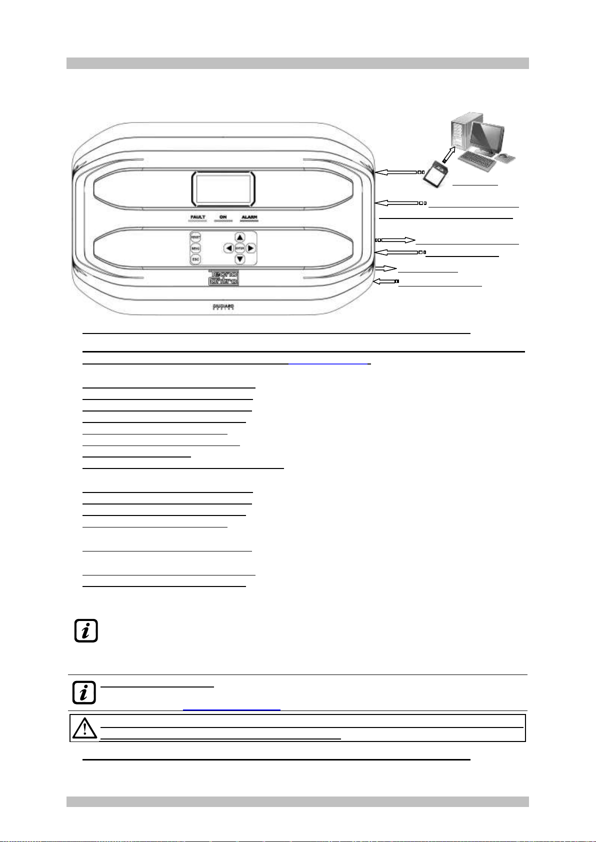
Fig.1 –CE408 - Wall mount housing
SD-CARD
no.5 or 9 Relay outputs
no.1 Logic input
Batteries (optional)

IST-1408.CE02.02/A CE408P User manual Pag. 6/43
TECNOCONTROL S.r.l. - Via Miglioli, 47 20054 SEGRATE (MI) - Tel. 02. 26 92 28 90 - Fax 02. 21 33 734
Each Sensor can be configured in two ways quickly and easily:
Preconfigured Setup: Here you can choose one of the models of our production, (See list in Table 1),
which is then automatically set in the configuration recommended by the respective thresholds and
relay outputs. Is enough set the output number (relay) to complete the configuration.
Modifications of the other values are however allowed.
Generic Configuration: Here you can configure any type of sensor (compatible or a new model not
yet listed), manually entering all parameters.
Fig.2 - Eg installation with TS282 series detectors.
Each Sensor is protected and has a FAULT signal:
All sensors inputs are protected against short-circuit or wire breakings. If a short-circuit occurs, the
power supply to that input, is automatically stopped (all others continue to work properly). At the same
time, the FAULT signal is activated.
Each Sensor may be associated with a ZONE:
The sensors can be grouped into Zones (Max No.2), which can associate up to No.2 relay outputs
different for each alarm level and No.1 for the FAULT.
Each ZONE can be set according to operating LOGIC:
The logic used are the typical logic functions (OR, AND), management of adjacent sensors
(CORR.CON, CIRC.CON). Note that PARK-ITA is a function only for Italy standard (Italian Ministerial Decree DM
01/02/1986 replaced by DM 08/03/2015 and subsequent updates).
The Unit can manage up to No.5, or No.9 Alarm relays:
Each sensor has three alarm levels (Threshold 1, Threshold 2 and Threshold 3) and a FAULT,
freely addressable to any relay output. The control unit has no.5 relay already installed, which can be
increased to No.9 with the expansion card ES414.
The alarm thresholds can be configured with special mode of operation:
For use in car parking "PARKING EN" (EN 50545-1) or to the workplace, such as exposure limit value
TLV.
Each output (relay) can be configured as follows:
- Silenceable: the output is disabled for the Silence time, when RESET is carried out and the sensor
is above the set threshold. This function can, for example, be used for the outputs connected to
audible warning devices.
- Silence Time: is the time, adjustable from 0 to 300 seconds, so Silenceable output (e.g. relay connected to
a siren) is disabled when the RESET is performed and a sensor is above the set threshold
- Hysteresis ON: is the delay, adjustable from 0 to 300 seconds, of the relay, associated with an alarm
threshold.
- Hysteresis OFF: is the delay, adjustable from 0 to 300 seconds, of the relay to return to normal condition,
when it ends the alarm.
- Time ON: is adjustable from 0 to 300 seconds. This function can only be used if you want to stop the alarm
output after a finite time, even if the sensor remains above the alarm threshold set (This function
cannot be used in conjunction with Hysteresis OFF delay). For example you can use it to enable
devices that cannot be powered down, or to send a pulse to a phone dialer.
S1
S8
S2
Elettrovalvola intercettazione gas
Gas cut-off solenoid valve
Électrovanne de coupure du gaz
Ingresso Logico AUX (es. PULSANTE)
AUX Logic input (eg. BUTTON)
Entrée logique AUX (par ex. BOUTON)
SE301
SIRENA / SIREN
RILEVATORI GAS
GAS DETECTORS / SONDES

IST-1408.CE02.02/A CE408P User manual Pag. 7/43
TECNOCONTROL S.r.l. - Via Miglioli, 47 20054 SEGRATE (MI) - Tel. 02. 26 92 28 90 - Fax 02. 21 33 734
- Memorized: the relay remains in alarm, even if the sensor returns below the threshold (this function
does not work if the Time ON or into Hysteresis OFF has already been inserted a value other than
zero), to return to normal conditions must be done RESET. Serves, for example, to prevent the
accidental or unauthorized resetting of a block valve of the gas, without first checking the cause of
the alarm.
-Positive Logic: the operation of the relay can be set normally activated or in positive logic,
therefore, if the relay fails, or is completely out of power, automatically moves into the Alarm
position, the NC contact becomes NO.
The Control Unit has a BUZZER inside:
The internal Buzzer sounds a Beep every touch of the keyboard. It can also be set to sound in case of
Fault and / or Alarm.
The Control Unit can store the Events:
The system can store up to 100 events comprising Alarms, Faults, Power ON, Mains blackout and
Resetting, that can be re-called at any time.
The Control Unit has an SD-CARD slot, it can be used for:
Future updates of the Control Unit firmware.
The Control Unit is protected by 3 LEVELS of PASSWORD:
Some menus are accessible up to three password levels, with a code composed of 4 numbers. The
levels are for access to functions, used by the respective authorized persons:
LEVEL 1: for the User
LEVEL 2: for the Installer or Maintenance technician.
LEVEL 3: Reserved - Only accessible for factory settings.

IST-1408.CE02.02/A CE408P User manual Pag. 8/43
TECNOCONTROL S.r.l. - Via Miglioli, 47 20054 SEGRATE (MI) - Tel. 02. 26 92 28 90 - Fax 02. 21 33 734
CONTROL UNIT INSTALLATION
THE FOLLOWING INSTRUCTIONS DESCRIBES ALL THE CONTROL UNIT
SYSTEM SETUP PROCEDURES AND THE INSTALLATION PROCEDURES TO
BE EXECUTED ONLY BY AUTHORISED AND EXPERIENCED STAFF.
WARNING: The unit is to be installed in an area protected from direct sunlight
and rain. Please note that for safety the unit is to be installed in safe areas
where there are present or can form flammable atmospheres and
concentrations exceeding 24% volume of oxygen.
CLEANING: To clean the exterior of the enclosure, use a soft damp cloth with water; do not use
solvents or abrasive cleaners.
POSITIONING: The unit should be mounted on the wall using 4 screws and wall plugs (Ø 6 mm) or 4
M4 screws and nuts, if the wall is not in masonry. The housing's base must be fixed through the 4
holes, on the sides of the base (Fig.3). The electrical connections should be executed all on the
housing base.
Fig 3 –Dimensions and Template for wall mounting.
The cover unlocks (with a coin) by turning 90° the 4 buttons located above and below the enclosure. It
is opened by pulling and then rotating it up until it rests at the base.
OPEN –CLOSING THE HOUSING
The housing has two sliding internal hinges. To open the case, you must:
1- With a coin or screwdriver (blade 10-12 mm), unlock the 4 closing buttons, turning them 90°
clockwise.
2- Gently, pull the cover outwards of about 4 cm and then rotate it up and place it on the upper edge
of the base housing, in this way remain in the open position.
To close the housing act in reverse order. Pay attention that the cover and the locking mechanism
enter into place. Finally block 4 buttons, turning 90 ° counterclockwise. To facilitate the closure, press
on the lid, the buttons, which are eccentric, will bring the lid to adhere to the base housing.
APRE
OPENS
OUVERT
CHIUDE
CLOSES
FERME
DIMA DI FISSAGGIO A PARETE
n.4 Fori per Tasselli a muro Ø 6mm
TEMPLATE FOR WALL MOUNTING
No.4 holes for wall plugs Ø 6mmn.
PATRON DE FIXATION AU MUR
4 Trous pour chevilles Ø 6mm
130 mm
342 mm

IST-1408.CE02.02/A CE408P User manual Pag. 9/43
TECNOCONTROL S.r.l. - Via Miglioli, 47 20054 SEGRATE (MI) - Tel. 02. 26 92 28 90 - Fax 02. 21 33 734
ELECTRICAL CONNECTIONS
The electrical connections should be executed all on the housing base.
The details of the connections to the mains, the two batteries, the AUX input and relay output
R9 are illustrated in Figure 4. While the details of the connections to the sensors and the other
outputs are illustrated in Figure 5.
The terminals are of "polarized inlet" type (1). We suggest to use
lugs adequate to the conductors (2) and to fix the wires to the box
structure to avoid excessive stress to the circuits and to the
terminals. Use a screwdriver (3) with the right dimensions.
3
1
2
Input terminal,
plug-polarized.
Considering that, it should be normal procedure disconnect power to the electronic equipment when
installing, or changing the connections, or when disconnecting or connecting expansion cards.
IMPORTANT:TO AVOID IRREVERSIBLE DAMAGE,DISCONNECT THE POWER SUPPLY TO
THE CONTROL UNIT,MAINS POWER AND BATTERY (IF PRESENTS)DURING INSTALLATION
(WIRING CABLES)OR BEFORE YOU INSTALL ANY EXPANSION BOARDS OR UNPLUG OR RE-
CONNECT THE FLAT CABLE.
Only if necessary, for maintenance or installation requirements, the housing cover can be
separated from its base, first remove mains power and remove the batteries, then disconnect
the flat cable, press on the two side tabs as shown in Fig. 3.Then you need to release the cover
from sliding hinges (press fit). To reconnect it, proceed in reverse order and after hanging up
the lid hinges, push the flat cable into the connector, respecting the polarization, the two levers
close automatically locking it. Only then you can reconnect power supply.
BATTERIES:Inside the housing, it can also accommodate two 12V/1.3Ah Lead batteries connected
in series (Fig.5) to assure the system powering in case of mains blackout.
The battery life is about 20 minutes with No.8 sensors, but each detector in less increases the
autonomy of about 4 min.
(The batteries are not included in the delivery, but are available on request). If required, to
increase the autonomy, No.2 12V, 3Ah or 7Ah batteries connected in series can be used,
but due to their size, they must be installed outside the control unit.
Considering that each detector absorbs 0.08A/h from the battery, the autonomy, with 8
detectors, becomes: about 4 hours with 3Ah batteries (each sensor less increases the
autonomy by about 30 min) and about 8 hours with 7Ah (each sensor less increases the
autonomy of about 60 minutes).
CABLE GLANDS: the lower side of the housing has 13 inputs designed for metric cable glands (ISO
pitch 1.5 mm). No.10 are for glands M16x1.5 mm (that accept external cables Ø 4÷8 mm) and n.3 are
for glands M20x1.5 mm (that accept external cables Ø 6÷12 mm).
These passages are closed, but they are not manually breakable, according to the installation
requirements, they must be drilling. To facilitate the operation, they have a centering for the drill bit.
Please, pay attention not touch the tip of the internal circuits or the power supply cables
To guarantee the degree of protection of the enclosure, it is recommended to use cable glands with
protection IP55 or higher.
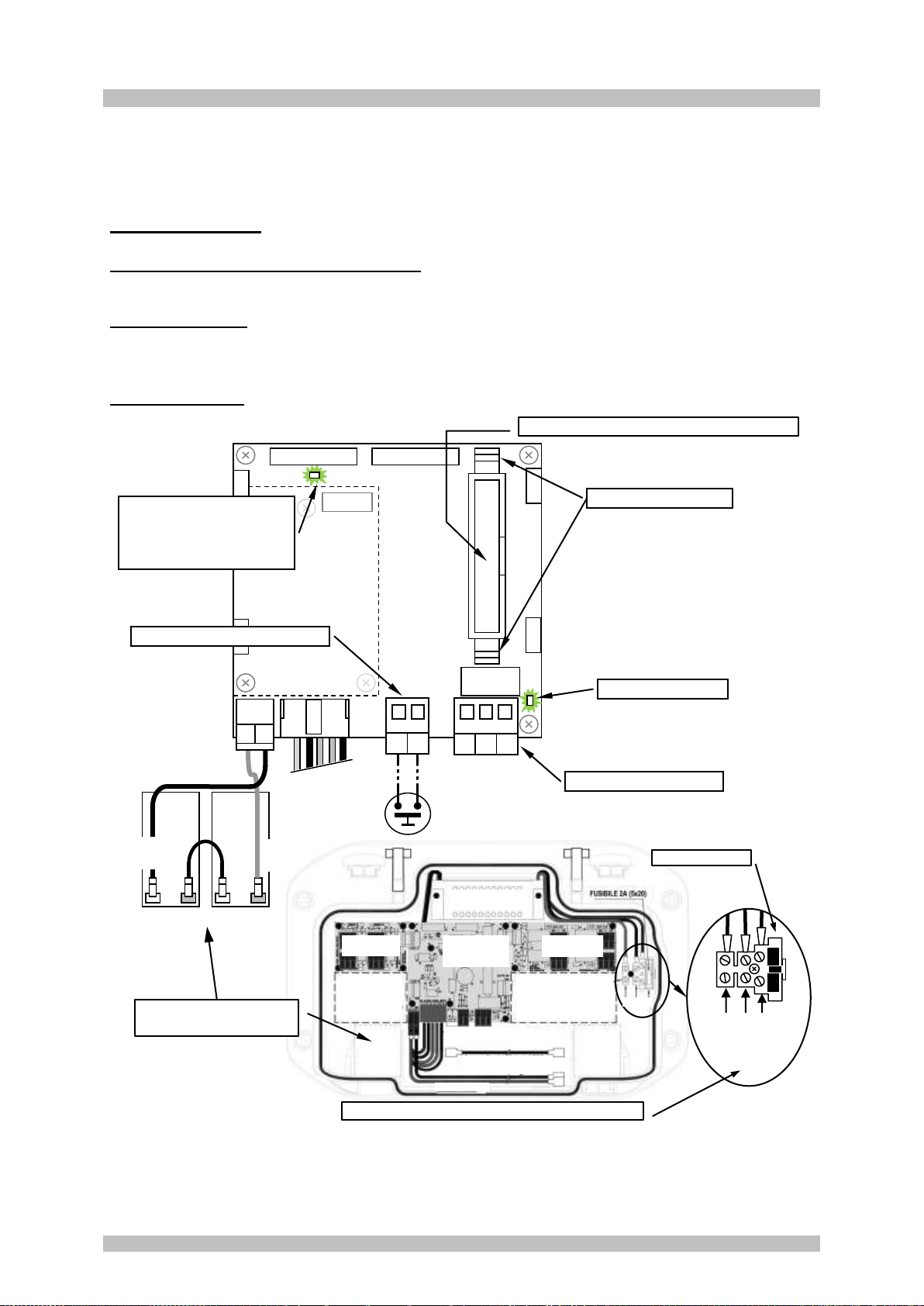
Fig.4 –Inputs for cable glands
Centro guidapunta
Center for the drill bit
Centre de guidage
Ingresso Alimentazione di Rete
Mains power supply Input
Entrée Alimentation Reseau
Ingressi rilevatori
Detectors Inputs
Entrées des sondes
IST-1408.CE02.02/A CE408P User manual Pag. 10/43
TECNOCONTROL S.r.l. - Via Miglioli, 47 20054 SEGRATE (MI) - Tel. 02. 26 92 28 90 - Fax 02. 21 33 734
Power connection
The installation must include a power line protection device. To the mains line, a bipolar disconnecting
switch dedicated for the gas detection system. The device, clearly identified, must act only on Phase
and Neutral, but not on the Earth. It is advisable to also provide for a surge protector, lightning etc.
Mains Power Supply (90÷264Vdc / 47÷63Hz) should be connected to terminal L, Nand Earth at the
right of the housing base. The terminal has a protective fuse (5x20) 2A.
The two 12V/1.3Ah Lead internal batteries if required should be connected in series to BAT+ (Red)
and BAT-(Black) terminals. For the series connection, use the black cable supplied with two terminals
(4.8 mm Fastens).
The auxiliary input (AUX) can be used to connect devices with a NO or NC contact (gas sensors with
relay contacts, smoke sensors, buttons, etc.). It can be configured to activate one of the available
relays. It can be connected to multiple devices if it’s are homogeneous. (If the device has an NC contact
must be connected in series or in parallel if it’s have all a contact NO).
Output Relay No.9 has the same characteristics and use of those described on the next page.
Fig 5 –CE408P Wiring diagram for Power, Batteries, AUX input and relay output No.9.
Outputs board
(Relays 1÷4)
Inputs board
(1÷4)
Main Board
Input AUX and
Outputs Relay 9
Position Expansion board
ES414 (Relays 5÷8)
Position
Expansion
board ES404
(Inputs 5÷8)
Neutro
Terra
Linea
Fuse (5x20) 2A
AL120 Power supply
(AC/DC 27,6V-60W)
Battery
n.1
Battery
n.2
Battery Cables
N T L
-+- +
B
-
B+
B-
NC
C
NO
A
A
Auxiliary Input Terminal AUX
n.2 Batterie 12V / 1.3Ah
Connected in Series
Flat-cable connector for cover connection
Relay 9 output terminal
LED: Batt TEST ON
The LED lights up when
checking functioning of
batteries (if installed).
LED: OUT 9 = ON
Press to Open
TO AVOID IRREVERSIBLE DAMAGE,
DISCONNECT THE POWER SUPPLY TO
THE CONTROL PANEL,MAINS POWER
AND BATTERY (IF PRESENTS)BEFORE
YOU UNPLUG OR RE-CONNECT THE
FLAT CABLE.
90÷ 264 Vac / 47÷63Hz Mains power supply terminal
B+
Red
B-
Black
IST-1408.CE02.02/A CE408P User manual Pag. 11/43
TECNOCONTROL S.r.l. - Via Miglioli, 47 20054 SEGRATE (MI) - Tel. 02. 26 92 28 90 - Fax 02. 21 33 734
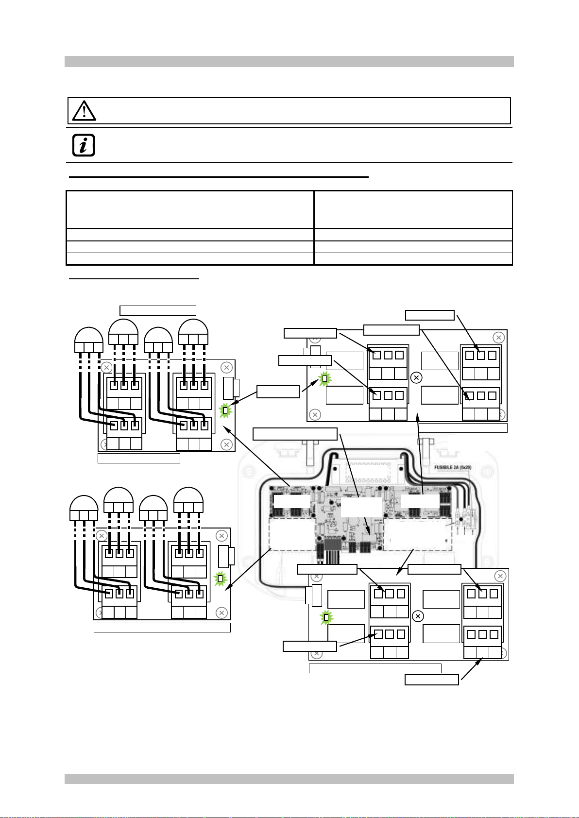
Connection with Gas Detectors (Sensors)
Please always refer to the specific instructions supplied with detectors.
Please note that the Control Unit has a card with no.4 outputs. An ES414 board can be
installed to have a total of 9 outputs. In the diagrams, for simplicity, they are always indicated
with all the Outputs.
Cable section and distance between Control Unit and Sensors: They must be 3-pole shielded
cables, with a section suitable for the distance as indicated below in the table.
Distanza massima di ogni rilevatore dalla centrale
Maximum distance of each detector from the control panel.
Distance maximale de chaque détecteur du panneau de contrôle
Tipo di Cavo schermato
Shielded Cable Type
Type de câble a écran
Max. 200 metri / meters / mètres
3 x 1 mm2Schermato / Shielded / à écran
Max. 400 metri / meters / mètres
3 x 1,5 mm2Schermato / Shielded / à écran
Max. 600 metri / meters / mètres
3 x 2,5 mm2Schermato / Shielded / à écran
Connection of the detectors: (Sensors 1÷8) is carried out on the Input boards (4 ÷ 20mA) mounted
in the base on the left, the terminals “+”, “-” and “S” must be connected to the corresponding terminals
of the detector.
The cable shield must be connected only from the Control Unit side and on a single "EARTH" point
which must be equipotential. On each detector (sensor) it will be necessary to use two cable glands,
one for the input and one for the output.
N T L
Outputs board relays 1÷4
NA
C
NC
NA
C
NC
NA
C
NC
NA
C
NC
Relay 1
Relay 2
Relay 3
Relay 4
ES404 Expansion board with inputs 5÷8
+
S
-
+
S
-
+
S
-
+
S
-
S5
+
S
-
S6
+
S
-
S8
+
S
-
S7
+
S
-
LED: ON
Fig 6 –Wiring diagram for Inputs
Sensor 4 to 20mA and relay Outputs
+
S
-
+
S
-
+
S
-
+
S
-
S1
+
S
-
S2
+
S
-
S4
+
S
-
S3
+
S
-
Input board 1÷4
Gas Detectors 1 to 4
Outputs board
(Relays 1÷4)
Inputs board
(1÷4)
Position Expansion
board
ES414 (Relays 5÷8)
Position
Expansion board
ES404
(Inputs 5÷8)
Relay n.9 - See Fig.4
Main Board
Input AUX and
Outputs Relay 9
NA
C
NC
NA
C
NC
NA
C
NC
NA
C
NC
ES414 - Expansion board with relays 5÷8
Relay 7
Relay 5
Relay 6
Relay 8
NA=NO

IST-1408.CE02.02/A CE408P User manual Pag. 12/43
TECNOCONTROL S.r.l. - Via Miglioli, 47 20054 SEGRATE (MI) - Tel. 02. 26 92 28 90 - Fax 02. 21 33 734
IMPORTANT ADVICE: before installing and configuring the control unit,
evaluate how many alarm devices are connected to the relays to determine how
many relays are needed and how they should act. Please see in SENSORS>
Configure> Description of the items related to the relay outputs.
Please note that the unit has No.5 outputs (relays) that can be increased by installing the
ES414 expansion board to have a total of 9 outputs. The diagrams, for simplicity, show all
relays outputs.
The connection to the internal outputs (relays 1 to 9) should be performed on the outputs board,
mounted in the base, on the right. The relay output no.9 is located on the central board, see Figure 5.
The relays nominal load is 250 VAC - 2 A or 30 VDC –2 A (resistive load).
NOTE: in Italian the indication NA means NO (Normally Open) while the others are the same.
The relay have changeover free voltage contacts, on the boards, the indications NO (Normally Open),
NC (Normally Closed), C (Common), refer to the relays in the normal position (not powered). If an output is
configured as POSITIVE LOGIC, the NO contact will become NC and NC will become NA.
TO AVOID IRREVERSIBLE DAMAGE,DISCONNECT THE POWER SUPPLY TO THE
CONTROL UNIT,MAINS POWER AND BATTERY (IF PRESENTS)BEFORE YOU UNPLUG
OR RE-CONNECT,ANY EXPANSION CARD.
IST-1408.CE02.02/A CE408P User manual Pag. 13/43
TECNOCONTROL S.r.l. - Via Miglioli, 47 20054 SEGRATE (MI) - Tel. 02. 26 92 28 90 - Fax 02. 21 33 734
USE OF THE CONTROL UNIT
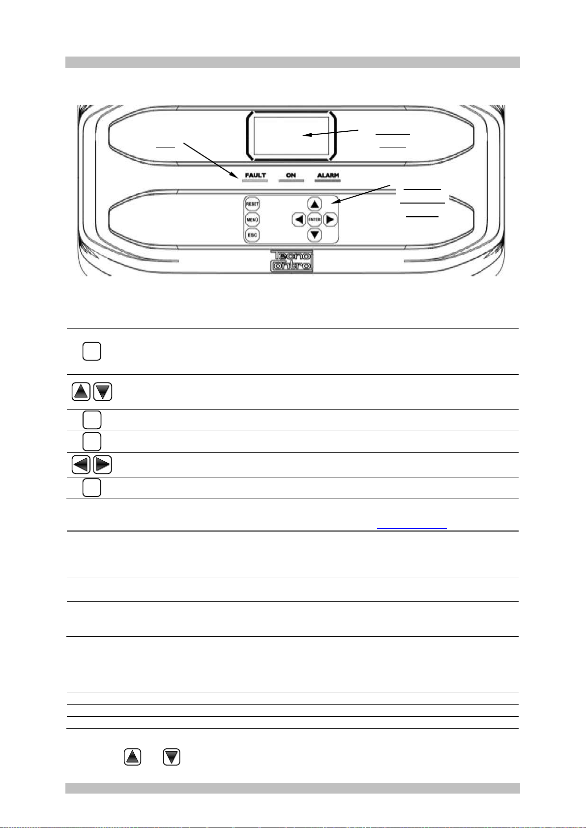
Fig.7 –CE408P Keyboard
Keyboard
The keyboard is backlit. To save energy, the brightness is reduced to half after 10 seconds of non-use.
RESET
Can only be used on the main screen, it is used to reset the latched outputs to normal
operation, but only if the Sensor or Zone or Input has returned from the alarm condition. If
there are active alarms, outputs configured as Silenceable (e.g. alarm) returns to normal
operating conditions only for the time of silencing by default.
Scroll through the display screens and the numeric digits up and down.
Keeping the key pressed increases the values' speed scrolling. In the main screen
changes to display the status of sensors, Logic Input and configured zones.
MENÙ
Call up the Main Menu from any screen.
ENTER
Confirm the inserted data and in the Main Screen allows you to select the detail’s sensors.
Scroll through the pages (6 sensors at a time and 7 events at a time), and input fields.
Keeping the key pressed increases the speed scrolling.
ESC
Cancel an operation and in the main screen is used to enter to Main Menu.
LEDs indications
The unit has 3 LEDs that show the operating status of the control unit (see also appendix).
FAULT
(Yellow LED)
Flashing = Preheat (Start Unit) or in Service or Firmware Update.
Fixed ON = Fault (Sensor or Areas) + Buzzer if enabled.
Short flashing = Output relay associated with a latched Fault.
Rapid flashing = Batteries Faulty or Disconnected.
ON
(Green LED)
Fixed ON = Operation with mains power.
Flashing = Operation with the batteries.
ALARM
(Red LED)
Fixed ON = Alarm 3 is active (Sensor or Zone) + Buzzer if enabled.
Flashing = Alarm 1 and / or 2 active (sensor or area or logic input).
Short flashing = Alarm latched (indented) (sensor or area or logic input).
Internal Buzzer indication
The unit has an internal buzzer that emits a beep when a key is pressed. It can also be configured to
sound in the event of a Fault and / or an Alarm.
Sound short (0.1s)
is always active
Confirms the pressing of a key
Continuous sound
if configured
Fault (Sensor or Zone)
Continuous sound
if configured
Alarm 3 is active (Sensor or Zone)
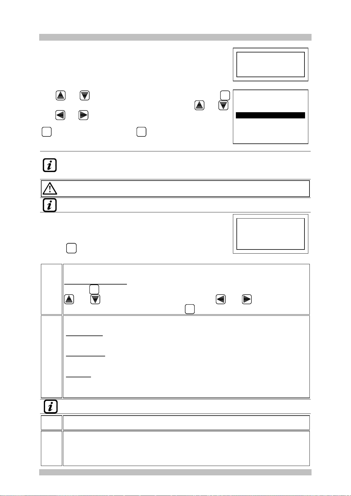
Single digit numeric field (password entry, etc.)
By pressing
and
key, the number is displayed in the field.
Tastiera
Keyboard
Clavier
Display
Ecran
LED

IST-1408.CE02.02/A CE408P User manual Pag. 14/43
TECNOCONTROL S.r.l. - Via Miglioli, 47 20054 SEGRATE (MI) - Tel. 02. 26 92 28 90 - Fax 02. 21 33 734
Screens 'Enable ...', 'Disable ...', 'Copy ...', 'Delete ...', 'Settings-> Date & Time':
Pressing the first time,
key, the number is displayed in its field (deleting any existing number), and
the next digits will be always inserted to the right of the number.
Example: to enter the number “12”, press
once, then press
to
move to the right and then press
twice.
If the number exceeds the maximum acceptable value, message will
appear "PARAMETER OUT OF RANGE".
Display –All other Screens:
As above, but in addition, when you press the
key, the last digit entered will be erased and you
can continue to enter additional digits.
Example: If you have entered the number "23", and then you want to change it to "25", simply press
the
then press
5 times.
If you have already entered a single digit, pressing
will display the minimum value accepted by
the field. Then, by pressing
or
key, the value already present is deleted and replaced with the
new one.
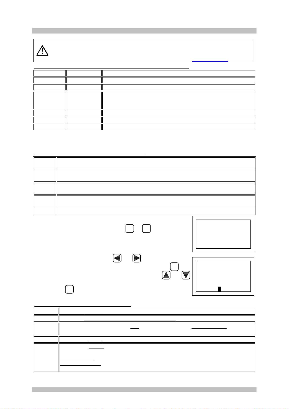
Display –Initial Screens
The unit, when powered, for 5 seconds shows the model name and the
installed firmware version.
This information shall be accessible also in the menu SettingsGeneralInfo.
For more information read the chapter Settings.
Only at first power (and only then) will be asked to choose
your language and to indicate if the battery is present. Use the
key
and
to scroll through the languages and pressing
the key
ENTER
to confirm the choice.
If necessary, these choices can be changed. Please see forward
Service
Battery.
Preheating Time
At each start-up, a decreasing count of 90 seconds will always start, it
is the time necessary for the control unit to start up and allow the
Sensors to stabilize.
Display –Main Screen
After the preheating time, appears the main screen that the control unit
displays in normal operation. The date is shown in the top row, the first 6
sensors (with the measured concentration and its state) and in the last
line, the battery status of charge (if installed) and presence of the mains.
PSW (PASSWORD) followed by a number, at the bottom left indicates the
current access level (eg PSW 2 indicates that Level 2 is enabled).
Symbols used to indicate the status of the battery (if installed):
Full Charge
Half Charge
Low Charge
Discharge
Flashing =
Faulty or Disconnected
If by mistake, the battery (configured present) being disconnected and/or connected with
the control unit, mains powered the yellow LED lights up on fast blinking.
Symbols used to indicate the presence of mains power:
= mains operation (is absent, when the power is by the batteries).
12:00 fri. 08/07/2020
1) 2 % LFL NORM
2)10.2 ppm AL.1
3) 300 ppm AL.3
4) - - - -
5) - - - -
6) - - - -
PSW 2
WARM UP
90
Wait . . .
PRESENCE BATTERY
1 - > NO
2 - > YES
L I N G U A - L A N G U A G E
L A N G U E - I D I O M A
1 - > ITALIANO
2 - > ENGLISH
3 - > FRANCAIS
4 - > ESPAÑOL
CE408
ver.
2.0X
PARAMETER
OUT OF SCALE
IST-1408.CE02.02/A CE408P User manual Pag. 15/43
TECNOCONTROL S.r.l. - Via Miglioli, 47 20054 SEGRATE (MI) - Tel. 02. 26 92 28 90 - Fax 02. 21 33 734
If the control unit, had lost the date and time, due to a malfunction or discharge of the clock
backup battery, screen will be displayed for entering updated values (The unit's safety
functions are guaranteed, except those involving the use of date that will be wrong). By
changing these parameters, see below, the section SETTINGSDATE and TIME.
The status of a sensor, which appears on the main screen, may be:
- - - -
Not configured
The detector is not Configured
* * * *
Disable
Detector is disabling. The outputs (relay) are not activated if an alarm occurs.
FAULT
Sensor failure
General information, of a faulty detector
NORM.
Normal
There is no gas and there are no active alarms. The text blinks when
relay output is latched (Detector or Zone, returned to normality after an alarm or
a fault).
AL.1
Alarm 1
The first alarm threshold has been exceeded
AL.2
Alarm 2
The second alarm threshold has been exceeded
AL.3
Alarm 3
The third alarm threshold has been exceeded.
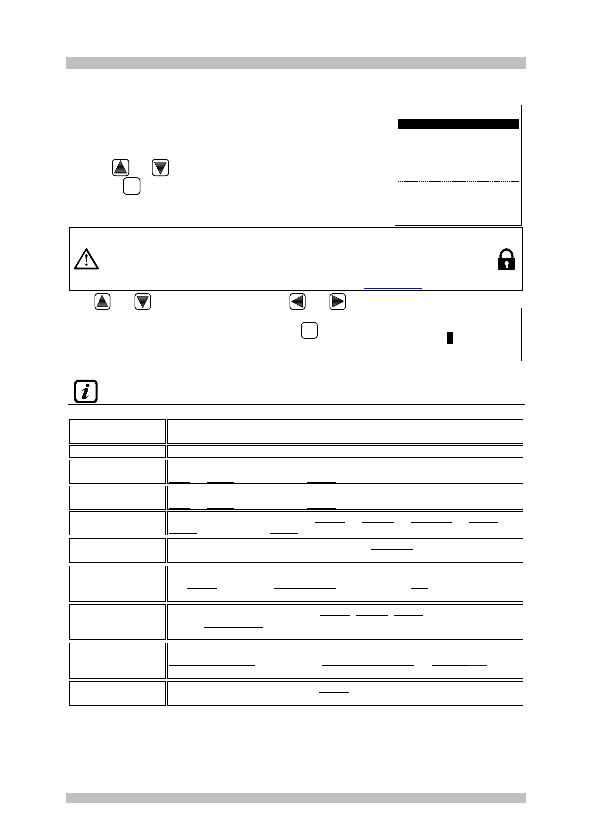
When a detector, a logic input or a zone, activate a relay output, the summary screen of the status of
the Alarms and Faults appears. This allows checking quickly, the total number of active relays and
their relative alarm level.
The details of the individual items is as follows:
FAULT
Indicates the number of active relays, relative to the Fault, of a sensor or a group of
sensors that belong to a zone.
AL. 1
Indicates the number of active relays, relating to exceeding the threshold of alarm 1, of a
sensor or a group of sensors that belong to a zone.
AL. 2
Indicates the number of active relays, related to exceeding the threshold of alarm 2, of a
sensor or a group of sensors that belong to a zone.
AL .3
Indicates the number of active relays, relating to exceeding the alarm threshold 3, of a
sensor or a group of sensors that belong to a zone.
INPUT
Indicates the number of active relay, LOGIC INPUT.
The screen can be closed by pressing
ESC
or
RESET
key. If the alarms
persist, the screen reappears after 10 minutes. If a new alarm occurs
the screen will appear again automatically.
From the Main screen, by pressing
and
keys, to scroll through
the sensors, displayed in groups of 6 at a time. Pressing
ENTER
, key
highlights the sensor in the first row. While, using the keys
and
to scroll through the sensors (in the page) shown on the display.
Pressing the
ENTER
key again, you view the details of the highlighted
sensor, (of course only if it is configured).
Explanations of the details are as follows:
1st row
Shows the number of the sensor (Gas Detector).
2nd row
Shows the name of the detected gas or its formula .
3rd row
Shows the currently measured gas concentration and the unit of measure and current
value (mA) (current generated by the sensor).
4th row
Indicates the Zone.
5th-6throw
Indicates the output number (Relay), corresponding respectively to:
1st Threshold (AL1) 2nd Threshold (AL2) 3rd Threshold (AL3) FAULT.
Value 0(zero) indicates, at that threshold, the output not been assigned, while the
highlighted value indicates that output relay is currently active (alarm). The values are
real time updated.
N. 1
GAS:
METHANE
2 % LFL
5.60 mA
ZONE:
0
OUTPUT
0 1 29
ALARM STATUS
FAULT:
00
AL 1:
01
AL 2:
00
AL 3:
03
INPUT:
00
Press Reset/Esc

IST-1408.CE02.02/A CE408P User manual Pag. 16/43
TECNOCONTROL S.r.l. - Via Miglioli, 47 20054 SEGRATE (MI) - Tel. 02. 26 92 28 90 - Fax 02. 21 33 734
Pressing
ESC
key it returns to the screen of the sensors. Press
ESC
again, to return to the Main
Screen.
Using the keys
and
is displayed, in cyclic mode, the situation of
the Zones (from Z1 and Z2) and the Logic Input AUX (I1).
The status of a LOGIC INPUT can be configured LOW (normally open
contact) or HIGH (normally closed contact) it can only be ACTIVE or
DEACTIVE, while a ZONE has the same states as a Sensor, except the
full scale.
Press
ESC
to enter the Main Menu.
The Control Unit has No. 2 Zones and No.1 Logic Input.
12:00 fri 08/07/2020
I1) LOW DEACTIVE
12:00 fri 08/07/2020
Z1) NORM.
Z2) - - - -
IST-1408.CE02.02/A CE408P User manual Pag. 17/43
TECNOCONTROL S.r.l. - Via Miglioli, 47 20054 SEGRATE (MI) - Tel. 02. 26 92 28 90 - Fax 02. 21 33 734
MAIN MENU
The Control Unit is provided with a main menu from which you can
manage all of its functions.
The name of each line indicates the thematic area on which we can take
action, by accessing the corresponding submenus.
Pressing
and
key to scroll through the menus.
Than press
ENTER
to enter in the corresponding submenus.
The Submenu 2-RESERVED, is not accessible, is not currently enabled,
is reserved for other functions.
Some submenus are protected by Level 1 or Level 2 passwords, indicated by the
“padlock” symbol visible when the level was not enabled.
When a protected menu is selected, the request to enter the specific Password
appears. When a menu is enabled, all others of the same level will be enabled and the
"locks" disappear. Further information can be found in the Access menu section.
With
and
you can enter the value, with
and
keys you
can move from one number to another.
After entering the Password, move to OK and press
ENTER
.
If the password entered is correct, the window will confirm the operation.
If an incorrect password was entered, the window alerts you of the error
and return to the screen ENTER PASSWORD
The required access level is indicated, when necessary, to the left of the individual items of the
manual.
List and short description of the accessible menus and the required or Password:
1-RESET
Performs silencing or Resetting the alarms and faults, not active and return to
the main menu.
2-RESERVED
Submenu currently not active, reserved for further functions.
3-SENSORS
Enter a submenu where you can enable , disable , configure , modify ,
copy , delete and view the details of the sensors.
4- INPUTS
Enter a submenu where you can enable , disable , configure , modify ,
copy , delete and view the details of the logic input.
5-ZONE
Enter a submenu where you can enable , disable , configure , modify ,
delete and view the details of the zones.
6- EVENTS
Enter a submenu where it is possible to view, all events or ones related only to
faults / alarms.
7- SETTINGS
Enter a submenu where you can change, the language , the display Contrast,
the buzzer settings , date and time and display Info (model, version and
business address).
8- PASSWORD
Enter a submenu where you can enable, disable, modify, the password, of the
relative access levels and .
The level is not accessible, is factory reserved.
9-SERVICE
Enter a submenu where you can perform electrical testing of the control unit
manage the battery , display the status of the sensors . Factory Test is
factory reserved.
0-SD CARD
Enter a submenu where you can update the Firmware of the control unit via
an SD Card
ENTER PASSWORD
LEVEL 1
0000
OK
CE408
1 RESET
2 RESERVED
3 SENSORS
4 INPUTS
5 ZONES
6 EVENTS
7 SETTINGS
8 PASSWORD
9 SERVICE
0 SD CARD
IST-1408.CE02.02/A CE408P User manual Pag. 18/43
TECNOCONTROL S.r.l. - Via Miglioli, 47 20054 SEGRATE (MI) - Tel. 02. 26 92 28 90 - Fax 02. 21 33 734
RESET
The RESET item in the main menu, performs the same function as
RESET
,
key, reset the latched outputs to normal operation, but only if the Sensor
or Zone or Logic Input has returned from the alarm condition.
If there are active alarms, outputs configured as Silenceable (e.g. an
alarm) return to normal operating conditions only for the time of
silencing.
When performing the RESET (with key or from the menu), the display
shows the confirm message for about 3 seconds, then the previous
screen reappears automatically.
SENSORS
In this submenu you can manage the sensors connected to the unit.
The 3-CONFIGURE menu, should only be used for a new
sensor, to modify the parameters of an already configured
sensor only use the 6-MODIFY menu.
Below, the individual items are described in detail, with the same level password, which is indicated in
parentheses.
SENSORS-ENABLE / DISABLE (Level 1):
These two items allow you to enable or disable one or more sensors, even simultaneously.
A disabled sensor is displayed on the main screen, with “”.
The Disabled sensors will no longer activate the fault and alarm outputs (relays)
associated with them and therefore the devices connected to the relays will not be
activated. This function can be used to exclude Sensors, not yet installed, in failure, be
removed for repair or for a short time during maintenance, in order to avoid activating
the alarms and then block a plant not yet put into safety.
To enable or disable a sensor press
ENTER
key on the relevant item
highlighted. With
and
it is possible to select, if you take action
on a single sensor or on a group of sensors.
The first line, is acting on a single sensor. Pressing
ENTER
on the 1st, will
highlight the number of the sensor. Then you choose the desired
number, with
and
keys and then, pressing
ENTER
the confirmation
window will appear.
The 2nd line, acts on a group of sensors. Pressing
ENTER
on the 2nd line,
will highlight the 1st sensor’s number of the group.
If the two sensor numbers are the same, the effect is identical to the
management of the single sensor.
With
and
, you can choose the number of required sensor,
pressing
and
you change from one value to another, then
pressing
ENTER
again, confirmation window will appear.
Press
ENTER
to confirm, or to go back, press
ESC
. If the sensor or one of
the group’s sensors is not configured, a window notifies you that the
operation is not possible.
Then the screen returns to the selection of the sensor.
If you have selected a group of sensors, the ones that have been configured are enabled
or disable.
SENSOR
N. 1
NOT CONF.
STOP
CONFIRM ?
YES = ENTER
NO = ESC
ENABLE
SENSOR N.
FROM N. TO N.
ENABLE
SENSOR N.
FROM N. TO N.
SENSORS
1-ENABLE
2 DISABLE
3 CONFIGURE
4 COPY
5 DELETE
6 MODIFY
7 DETAILS
RESET
PERFORMED

IST-1408.CE02.02/A CE408P User manual Pag. 19/43
TECNOCONTROL S.r.l. - Via Miglioli, 47 20054 SEGRATE (MI) - Tel. 02. 26 92 28 90 - Fax 02. 21 33 734
If the procedure is correct, a window warns that the operation has been
successful. Then the screen returns to the start of the Enable / Disable
management
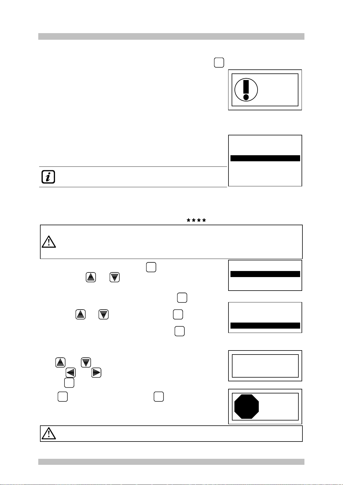
IMPORTANT: Before starting the setup, decide how many and which outputs are
to be used (relay) according to the type, to the requested operation and the
number of actuators installed and in which the alarm levels are associated.
CONFIGURE SENSORS (Level 2):
here are two ways to configure a sensor, but both can be configured
only of our production models (TABLES List detectors PRECONFIGURED)
that have some parameters not editable and others already preset, but it
all changed, must be entered only the outputs (relay number) you
want to activate.
The first way allows you to select, manually, one at a time sensor,
including ones that are preconfigured.
The second way allows you can manually enter all the parameters,
which are freely editable. This allows you to use compatible products
but not of our production or new models not yet included in the list of
pre-configured ones.
For safety, it is not allowed to set outputs separately. They can only be configured in
CONFIGURE or MODIFY a Sensor, a Logic Input or a Zone.
CONFIGURE - PRECONFIGURED SENSOR:
To start the configuration press
ENTER
on the relevant highlighted item.
With
or
and then pressing
ENTER
you can choose the number of
the sensor to be configured.
For safety, if you choose a previously configured sensor,
the screen that warns of the possible error, with you can
confirm with
ENTER
and continue, configuring it as if it were a
new sensor, instead of pressing
ESC
will cancel the
operation and you can choose another sensor.
The configuration of a dual sensor (TS255), uses 2 consecutive sensors (1-2, 3-4, or 2-3,
4-5 etc.) You should always start from the first configuration of the two.
Next, you can choose the model code.
To choose the desired one, its structure must be followed as described
below, first the first 2 letters must be chosen, then the 3 numbers and
then the other letters (if present) until the complete code of the model is
composed.
CODE STRUCTURE: our codes are made up of 2 letters that identify the type of product (e.g.
TS = signal transmitter), 3 numbers that identify some functional characteristics, (e.g. TS2xx =
mA signal output), other 2 or more letters specify the type of sensing element used and the
gas detected, e.g. TS282KM (K=catalytic and M = Methane), other letters or numbers, if
present, indicate other specific characteristics of the product.
With
and
you can scroll between the groups of letters and
numbers that make up the model, with
ENTER
you can confirm your choice
and move on. With
ESC
you can go back.
Example: for model TS282KM, first select TS and confirm by pressing
ENTER
. Then select the 2nd item TS282 and confirm with
ENTER
key. Finally
complete the selection by selecting the complete entry TS282KM and
press
ENTER
to confirm.
PRECONF. SENS.
SENSOR N. 1
MODEL: TS282KB
TS282KG
TS282KI
TS282KM
PRECONF. SENS.
SENSOR N. 1
MODEL: TS455
TS282
TS493
PRECONF. SENS.
SENSOR N. 1
MODEL: TS
SENSOR USED
CONTINUE ?
YES= ENTER
NO= ESC
PRECONF. SENS.
SENSOR N. 1
SENSORS CONFIG.
1 PRECONF. SENS.
2 GENERIC SENS.
SENSOR
N. 1
ENABLE
IST-1408.CE02.02/A CE408P User manual Pag. 20/43
TECNOCONTROL S.r.l. - Via Miglioli, 47 20054 SEGRATE (MI) - Tel. 02. 26 92 28 90 - Fax 02. 21 33 734
Chosen model, will appear a short reminder referring to the
configuration of voices OUTPUT 1, OUTPUT 2 and OUTPUT 3 that
activates the corresponding alarm outputs (relays) and the specific
parameters (delays) that define the operation mode of the relay outputs.
Chosen model, will load its configuration.
With
and
you can scroll through the various items. Press
ENTER
on the item, it is only highlighted the value, editable with
and
.
With
and
you move from one field to the other in the same row
(where applicable). The ETIC item, is explained later. Then by pressing
ENTER
the change is accepted. With
ESC
the previous value is restored
and the entire row is selected, indicating that it is possible to go back to
scrolling through the various items.
After the non-editable items, MODEL, TYPE, GAS, UoM. F.S. and AL. other fields have a
presetted value but can be changed. The only empty fields are OUTPUT 1, 2 and 3where the
number of the relay that will activate the corresponding alarm level (THRESHOLD 1, 2 and 3)
must be entered.
ATTENTION: it is not mandatory to assign an OUTPUT relay number, but if it is not
entered, alarm will not be activated. Number 0 (zero) indicates that no relay is assigned.
Only the configuration procedure of the two HYSTER.OFF / TIME ON functions is different from
that described above, and must be carried out as explained in the following pages.
Chosen model, will appear a short reminder referring to the
configuration of some particular parameters (delays) that define the
operation mode of the relay outputs.
The explanation is detailed below in section HYSTERESIS OFF.
Pressing
ENTER
the reading is confirmed and the pop-up disappears.
Description of items related to the Preconfigured sensor:
TAG
It is a 10-character label, selectable one at a time, where you can write a note or a reminder
for a sensor (e. FLOOR 2, BOILER, etc.).
AVAILABLE CHARACTERS: 0 ÷ 9 A ÷ Z ▓ (Space):; <=>? @
Pressing
ENTER
on the item (when it is in negative), only the 1st character is highlighted, with
and
, you scroll through the characters, with
and
you go to the next
character, then complete the text, by pressing
ENTER
you confirm the choice.
AL.
Defines the type of ALARM of the sensor and establishes how they should be set the
thresholds of the various alarm levels. In the specific:
INCREASING: The alarm levels must be set from the smallest to the largest or, if needed,
the same. (ALARM 1 ≤ ALARM 2 ≤ ALARM 3 ≤ FULL SCALE of the SENSOR). All our sensors, except
for oxygen ones, are set with this type of alarm.
DECREASING: The alarm levels must be set from the largest to the smallest value or, if
needed, the same. (ALARM 1 ≥ ALARM 2 ≥ ALARM 3 ≥ FULL SCALE of the SENSOR). Some oxygen
sensors can be set with this type of alarm.
OXYGEN: Alarm levels should be set to detect concentrations lower (deficiency) or higher
(excess) than the normal presence of oxygen in the air (20.9% v/v). (ALARM 2 ≤ ALARM 1 ≤
20.5% vol and ALARM 3 ≥ 21.2% vol and not beyond the FULL SCALE of the SENSOR). Our oxygen
sensors are set with this type of alarm.
Only for Oxygen detectors, ALARM 2 is displayed as AL
, while the ALARM 3 as AL
ZONE
ZONE: Sets the area that will be associated with the sensor. The number of available areas
is max 2. The area 0means that the sensor is not associated in any area
TLV
(Threshold Limit Values) are exposure limit values (OELs-Occupational Exposure Limits) for
toxic substances to which workers may be exposed every day for the entire duration of
working life without harmful effects. i.e. SENSOR SCALE ≥ ALARM 3 ≥ ALARM 1 ≥ ALARM
2 ≥ FAULT must be set in increasing order.Each alarm level is a value obtained with a
temporal average. TLVs in detail are:
NOTE: to use the TIME ON
parameter in the output
settings, select DELAY OFF line
and modify it with ENTER key.
ENTER to exit
PRECONF. SENS.
SENSOR N. 1
MODEL: TS282KM
TAG:
TYPE: Flammable
GAS: METHANE
UoM: % LFL
AL: INCREASING
CAUTION: If the number of the
relay will not be inserted, the
alarm will not be activated.
ENTER to exit
Table of contents
Other Tecnocontrol Control Unit manuals


Popular Control Unit manuals by other brands

iWave
iWave iW-RainboW-G18M Hardware user's guide

Siemens
Siemens 7KM4211-1BA00-3AA0 operating instructions

Elseta
Elseta IOMOD 8DI8DO user manual

Allen-Bradley
Allen-Bradley 1794-OW8 installation instructions

Val-Matic
Val-Matic FloodSafe Inflow Preventer Operation, maintenance and installation manual

Governors America
Governors America ESD5300 Series quick start guide


