Tecnocontrol CITY CE424P User manual

EN
IST-1424.CE02.02
File: IST-1424.CE02.02_CE424-EN (14.12.2016).docx
GAS CONTROL UNIT
CITY
CE424P
Max 24 Inputs 4÷20mA
USER INSTRUCTIONS
TECNOCONTROL S. .l.
Via Miglioli, 4 20090 SEGRATE (MI) Italy- Tel. (+39) 02 26922890 - Fax (+39)02 2133 34
http: www.tecnocont ol.it e-mail: info@tecnocont ol.it

IST-1424.CE02.02 CE424P / User Manual Pag. 2/50
TECNOCONTROL S. .l. - Via Miglioli, 47 20090 SEGRATE (MI) - Tel. 02. 26 92 28 90 - Fax 02. 21 33 734
Please ead and keep ca e of this manual and the manual of
installed senso s too.
All documentation relating to gas detection plant should be preserved, because it contains
the procedures to be used during the routines verification and / or during the periodic
calibration. We recommend that you always complete the Setup Memorandum Tables in the
last pages of this manual. This will facilitate any possible change to the configuration and/or
in case of additional sensors, and operations and maintenance service
INFORMATION AND WARNINGS OF USE
The CE424 is a control unit for gas alarm systems up to 24 independent detection points. The
simple installation and easy configuration via the buttons make the unit suitable for use in
many areas, both civil and industrial.
t should be noted that inappropriate use or lack of maintenance can affect the
operation of the device and thus preventing the proper activation of alarms with
potential serious consequences for the user.
TECNOCONTROL disclaims any responsibility if the product is misused, altered or not as
planned or outside the rated operating limits or put in work incorrectly.
The choice and use of
the product are the sole responsibility of the individual operator.
The rules, laws, etc.. mentioned, are the ones valid on the date of issue. n any case, must be
observed all applicable national regulations in the country of use.
The information contained in this document are accurate, current at the date of publication,
and are the result of continuous research and development, the specifications of this product
and what is indicated in this manual may be changed without notice.
The Central has a clock with the automatic DST change. n the absence of power
supply, the clock works with the lithium battery (on the board in the cover), its life, in
normal operation is over 5 years.
f the lithium battery is exhausted and the central remained completely without power, at
startup, you will need to enter the correct date and time (see page 32) and then the battery must
be replaced soon with a new one.
NOTES FOR READING INSTRUCTION
CE424P Control unit for 4 gas detectors, expandable up to 8 with 1 ES404. Equipped with # 5
relay outputs expandable to 9 with 1 ES4014. The unit has also # 1 Logic Input.
ES404
Expansion card with 4 inputs (4÷20mA) for gas detectors.
ES414
Expansion card with 4 relay outputs.
ES41
5
Expansion card with 1 RS485 serial port – Communication via Modbus RTU binary
RU Remote Unit CE380UR, with 8 input 4 to 20mA for gas detectors, which can be
installed up to 2 expansion cards ES380UR, each with 4 relay outputs.
SENSORS t is the name that, for simplicity, are indicated the various models of Remote Gas
Sensors, with current output 4 to 20mA, that can be connected to the CE424P.
FIRMWARE
Program inserted into the microcontroller which controls CE424P functioning.
Symbol that indicates an important warning in the instructions.
Symbol indicates information or additional explanation in the instructions.
Documento / Document name: IST-1424.CE02.02_CE424-EN (14.12.2016).docx
Oggetto / Subject : CE424P Wall mount Control Unit GIUGIARO design
Rev Data / Date Da / By Note
0 14/12/2016 UT/FG Document Edition

IST-1424.CE02.02 CE424P / User Manual Pag. 3/50
TECNOCONTROL S. .l. - Via Miglioli, 47 20090 SEGRATE (MI) - Tel. 02. 26 92 28 90 - Fax 02. 21 33 734
SOMMARIO
DESCRIPTION 5
Fig.1 - CE424P - Wall mount housing 5
CE424P INSTALLATION 8
Fig 2 – CE424P Dimensions and Template for wall mounting 8
OPENING-CLOSING the HOUSING 8
The housing has two sliding internal hinges To open the case, you must: 8
ELECTRICAL CONNECTIONS 9
POWER CONNECTION 10
Fig 3 – CE424P Wiring diagram for Power, Batteries, AUX input and output 9. 10
CoNNECTION WITH GAS DETECTORS 11
Fig 4 – CE424P Wiring diagram for Inputs Sensor 4 to 20mA and relay Outputs 11
Fig 5 – CE424P Remote units Connection with 4 to 20mA detectors input and output relays. 12
EXPANSION BOARD ES415 – MODBUS 13
Fig 6 – CE424P Expansion card ES415 with COM3 (RS485) Modbus serial port. 13
UNIT’S OPERATION 14
Fig 5 – CE424P Keyboard 14
MAIN MENU 17
RESET 18
REMOTE UNITS 18
RU ENABLE/DISABLE (Level 1) 18
CONFIGURE (Level 2) 19
DELETE (Level 2) 20
MODIFY (Level 2) 20
DETAILS 20
SENSORS 21
ENABLE/DISABLE (Level 1) 21
CONFIGURE (Level 2) 22
COPY (Level 2) 25
DELETE (Level 2) 26
MODIFY (Level 2) 2
DETAILS 2
LOGIC INPUT 27
ENABLE/DISABLE (Level 1) 2
CONFIGURE (Level 2) 28
DELETE (Level 2) 28
MODIFY (Level 2) 29
DETAILS 29
ZONES 29
ENABLE/DISABLE (Level 1) 29
CONFIGURE (Level 2) 30
DELETE (Level 2) 31
MODIFY (Level 2) 31
DETAILS 31

IST-1424.CE02.02 CE424P / User Manual Pag. 4/50
TECNOCONTROL S. .l. - Via Miglioli, 47 20090 SEGRATE (MI) - Tel. 02. 26 92 28 90 - Fax 02. 21 33 734
EVENTS 32
ALARMS/FAULTS 32
ALL 32
SETTINGS 33
LANGUAGE (Level 1) 33
GENERALS 33
BUZZER (Level 1) 33
DATE and TIME (Level 1) 33
MODBUS (Level 2): 34
ACCESS MENU 35
ENABLE LEVEL 35
DISABLE LEVEL 35
MODIF. PASSWORD 35
SERVICE 36
ELECTRIC TEST (Level 2) 36
BATTERY (Level 2) 36
SENSORS STATUS (Level 2) 3
FACTORY TEST (Level 3) 3
SD CARD 3
UPDATE FIRMWA. (Level 2) 3
Fig.6- Board into housing cover 38
COPY CONF. FROM (Livello 2) 39
COPIA CONF. ON (Livello 2) 39
COPY EVENTS ON (Livello 2) 40
DATA LOGGING (Livello 2) 40
APPENDIX 41
CE424 Technical Specifications 41
TABLE with summary of Fault and Alarm messages 42
TABLE 1 43
List of PRECONFIGURED Sensors with Display and Replaceable Cartridge Sensor 43
List of PRECONFIGURED Sensors with Display and Replaceable Cartridge Sensor 44
List of PRECONFIGURED Sensors without Replaceable Cartridge Sensor 44
TABLE 2 – PRECONFIGURED values for TLV 44
TABLE 3 – PRECONFIGURED values for use with PARKING-EN (EN50545-1) 45
TABLE 4 – USED ONLY IN ITALY - Values to be set to use with PARKING-ITA (DM 1 02 1986)45
TABLE 3 - Relays operation's PRECONFIGURED parameters 45
SETUP MEMORANDUM TABLES 46
IST-1424.CE02.02 CE424P / User Manual Pag. 5/50
TECNOCONTROL S. .l. - Via Miglioli, 47 20090 SEGRATE (MI) - Tel. 02. 26 92 28 90 - Fax 02. 21 33 734
DESCRIPTION
• The CE424P is wall mount “GIUGIARO DESIGN” housing 379x241x133 mm:
• The CE424P can be connected to all of ou Gas Detecto s (Sensors):
The CE424 can control up to 4, 8, 16 or 24 remote gas detectors.
F om Janua y. 2017 the TS282xx (IP65) se ies, supe sede all TS220xx and the TS292xx.
(Example: TS292KM will become TS282KM or the TS220EO will become TS282EO)
- Three-Wire, 4÷20mA linear output models with “Replaceable Cartridge Sensor” for:
Flammable gases with Catalytic sensor (20% LEL range) TS292K(IP65) or TS293K(Ex”d”) series.
Flammable gases with Pellistor sensor (100% LEL range) TS292P(IP65) or TS293P (Ex”d”) series.
Flammable gases with nfrared sensor (100% LEL range) TS293I(Ex”d”) series.
Toxic gases with electrochemical cell TS220E (IP65) or TS293E (Ex”d”) series.
Carbon dioxide with nfrared sensor TS210IC2 (IP54), TS220IC2 (IP65) or TS293IC2 (Ex”d”).
Oxygen with electrochemical cell (25% volume range) TS220EO or TS293EO (Ex”d”).
With dual sensor for Parking TS255CB or TS255CN2.
Refrigerant gases with Semiconductor sensor TS220SFx (IP65) series.
- Three-Wire, 4÷20mA linear output models with Display and with “Replaceable Cartridge Sensor” for:
Flammable gases with Pellistor sensor (100% LEL range) TS593P (Ex "d") series.
Flammable gases with nfrared sensor (100% LEL range) TS593I (Ex”d”) series.
Toxic gases with electrochemical cell (25% volume range) TS593EO (Ex”d”).
- Should be connecting all models without the replaceable Cartridge:
Refrigerant gases with nfrared sensor TS210 F (IP42) series.
Flammable gases with Catalytic sensor SE192K (IP65) or SE193K (Ex”d”) series. They can only be
used in non-industrial environments, such as boiler rooms.
May be connected, even discontinued models. Detectors three-
wire 4 to 20mA linear for
flammable gases or those two-
wire 4 to 20mA linear for toxic gases or oxygen, produced until
December 2008. Or the R101or R102 for CO2 in production until December 2014.
nputs are configurable for 4÷20mA sensors with referred current to ground and operating
characteristics same as our products (unit in %LEL or ppm, minimum operating voltage,
absorption, load resistance etc.).
We accept
no liability for any malfunction, failure or damage caused by products not
compatible or not we produce
• Each Senso may be associated with a ZONE:
The sensors can be grouped into Zones (Max 6), which can associate up to 2 relay outputs
different for each alarm level and a FAULT.
n.1 RS485 (COM3) Modbus
n.2 RS485 (COM1 e COM2)
up to 16 detectors and 16 relay
outputs, with 2 remotes CE38 UR
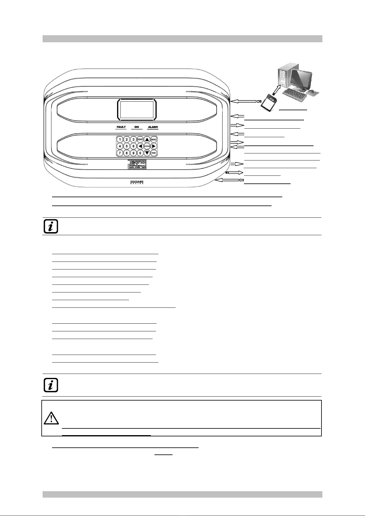
Fig.1 - CE424P - Wall mount housing
SD-CARD
5 or 9 Relay Outputs
n.1 Logic nput
4 or 8 Sensors nputs
Mains Supply 90÷264 VAC
Battery (optional)
IST-1424.CE02.02 CE424P / User Manual Pag. 6/50
TECNOCONTROL S. .l. - Via Miglioli, 47 20090 SEGRATE (MI) - Tel. 02. 26 92 28 90 - Fax 02. 21 33 734
• Each ZONE can be set acco ding to ope ating LOGIC:
The logic used are the typical logic functions (AND, OR), management of adjacent sensors
(CORR.CON, CIRC.CON). Note that PARK-ITA is a unction only or Italy (Italian Ministerial Decree 01/02/1986).
• Each INPUT (Senso ) is self-p otected and has a FAULT signal:
All sensors inputs are protected against short-circuit or wire breakings. If a short-circuit occurs,
the power supply to that input, is automatically stopped (all others continue to work properly). At
the same time, the FAULT signal is activated.
• Each Senso can be configu ed in two ways:
P econfigu ed Setup: Here you can choose one of the models of our production, (See list in Table
on page 4 ), which is then automatically set in the configuration recommended by the respective
thresholds and relay outputs. Is enough set the output number (relay) to complete the
configuration. The manual changes are, however, permitted.
Gene al Configu ation: Here you can configure any type of sensor (compatible or a new model
not yet listed), manually entering all parameters.
• The AUX input is configu able and can be associated with a elay output:
- Can be configured to activate one of the available relays and can be used by devices with NO or
NC contact outputs (gas sensors with a relay contact, smoke sensors, buttons, etc.).
• The CE424 can manage up to 5, 9, 17 o 25 Ala m elays:
Each sensor has three alarm levels (Th eshold 1, Th eshold 2 and Th eshold 3) and a FAULT,
freely addressable to any relay output.
• The ala m th esholds can be configu ed with special mode of ope ation:
For use in car parking "PARKING EN" (EN 50545-1) or to the workplace, such as exposure limit
value TLV.
• Each output ( elay) can be configu ed as follows:
- Silenceable: the output is disabled for the Silence time, when RESET is carried out and the
sensor is above the set threshold. This function can, for example, be used for the outputs
connected to audible warning devices.
- Silence Time: is the time, adjustable rom 0 to 300 seconds, so Silenceable output (e.g. relay connected
to a siren) is disabled when the RESET is performed and a sensor is above the set threshold
- Hyste esis ON: is the delay, adjustable rom 0 to 300 seconds, of the relay, associated with an alarm
threshold.
- Hyste esis OFF: is the delay, adjustable rom 0 to 300 seconds, of the relay to return to normal
condition, when it ends the alarm.
- Time ON: is adjustable rom 0 to 300 seconds. This function can only be used if you want to stop the
alarm output after a finite time, even if the sensor remains above the alarm threshold set (This
function cannot be used in conjunction with Hysteresis OFF delay). For example you can use it
to enable devices that cannot be powered down, or to send a pulse to a phone dialer.
- Memo ized: the relay remains in alarm, even if the sensor returns below the threshold (this
function does not work if the Time ON or into Hysteresis OFF has already been inserted a value
other than zero), to return to normal conditions must be done RESET. Serves, for example, to
prevent the accidental or unauthorized resetting of a block valve of the gas, without first checking
the cause of the alarm.
- Positive Logic: the operation of the relay can be set normally activated or in positive logic,
therefore, if the relay fails, or is completely out of power, automatically moves into the Alarm
position, the NC contact becomes NO.
• The CE424 have a BUZZER inside:
The internal Buzzer sounds a Beep every touch of the keyboard. It can also be set to sound in
case of Fault and / or Alarm.
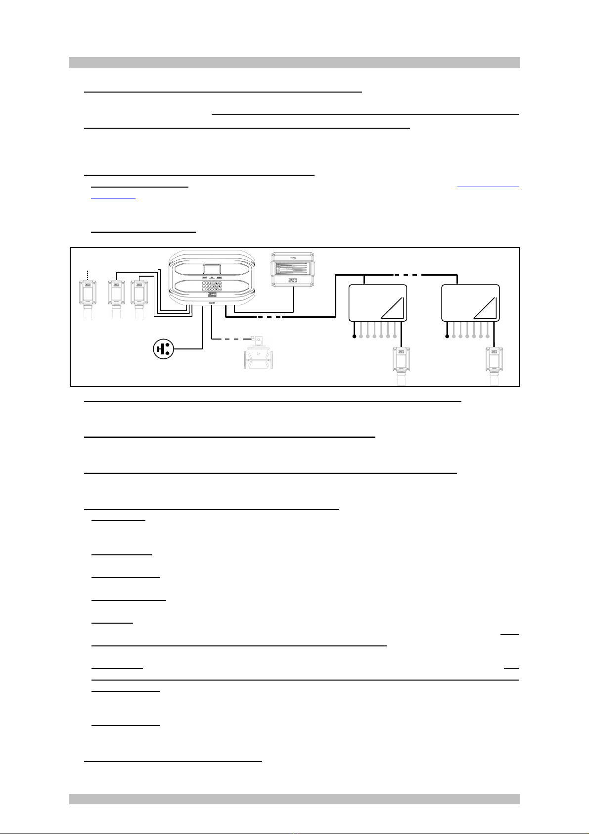
S1
S8
S2
1
S9
S 6
CE380UR
COM
RS485
2
S 7
S24
CE380UR
GAS VALVE
AUX INPUT
PUSH-BUTTON
SE30
GAS DETECTORS
GAS DETECTORS

IST-1424.CE02.02 CE424P / User Manual Pag. /50
TECNOCONTROL S. .l. - Via Miglioli, 47 20090 SEGRATE (MI) - Tel. 02. 26 92 28 90 - Fax 02. 21 33 734
• The CE424 can sto e the Events:
The system can store up to 100 events comprising Alarms, Faults, Power ON, Mains blackout and
Resetting, that can be re-called at any time.
• The CE424 has an SD CARD slot It can be used fo :
- Future updates of the central unit firmware.
- Loading or Saving the configuration of the control panel and rescue the events.
- Data Logger (Storing in time, of the values read by the sensors, in text format).
• The cent al CE424 has 2 RS485 se ial po ts:
On both ports, 1 or 2 can be connected remote units CE380UR.
• The CE424 is p otected by 3 LEVELS of PASSWORD:
Some menus are accessible up to three password levels, with a code composed of 4 numbers. The
levels are for access to functions, used by the respective authorized persons.
LEVEL 1: for the User
LEVEL 2: for the Installer or Maintenance technician.
LEVEL 3: only for Manufacturer.
COM1
RS485
CE380UR
1
S9
S 6
COM2
RS485
CE380UR
2
S 9
S24
COM1
RS485
CE380UR
1
S9
S 6
CE380UR
2
S 9
S24
IST-1424.CE02.02 CE424P / User Manual Pag. 8/50
TECNOCONTROL S. .l. - Via Miglioli, 47 20090 SEGRATE (MI) - Tel. 02. 26 92 28 90 - Fax 02. 21 33 734
THE FOLLOWING INSTRUCTIONS DESCRIBES ALL THE CENTRAL SYSTEM
SETUP PROCEDURES AS WELL AS THE INSTALLATION PROCEDURES TO
BE EXECUTED ONLY BY AUTHORISED AND EXPERIENCED PERSONNEL.
CE424P INSTALLATION
WARNING: The CE408 is to be installed in an area protected from direct sunlight and rain. Please note
that for safety the CE408 is to be installed in safe areas where there are present or can form
flammable atmospheres and concentrations exceeding 24 % volume oxygen.
CLEANING: To clean the exterior of the enclosure, use a soft damp cloth with water, do not use solvents
or abrasive cleaners.
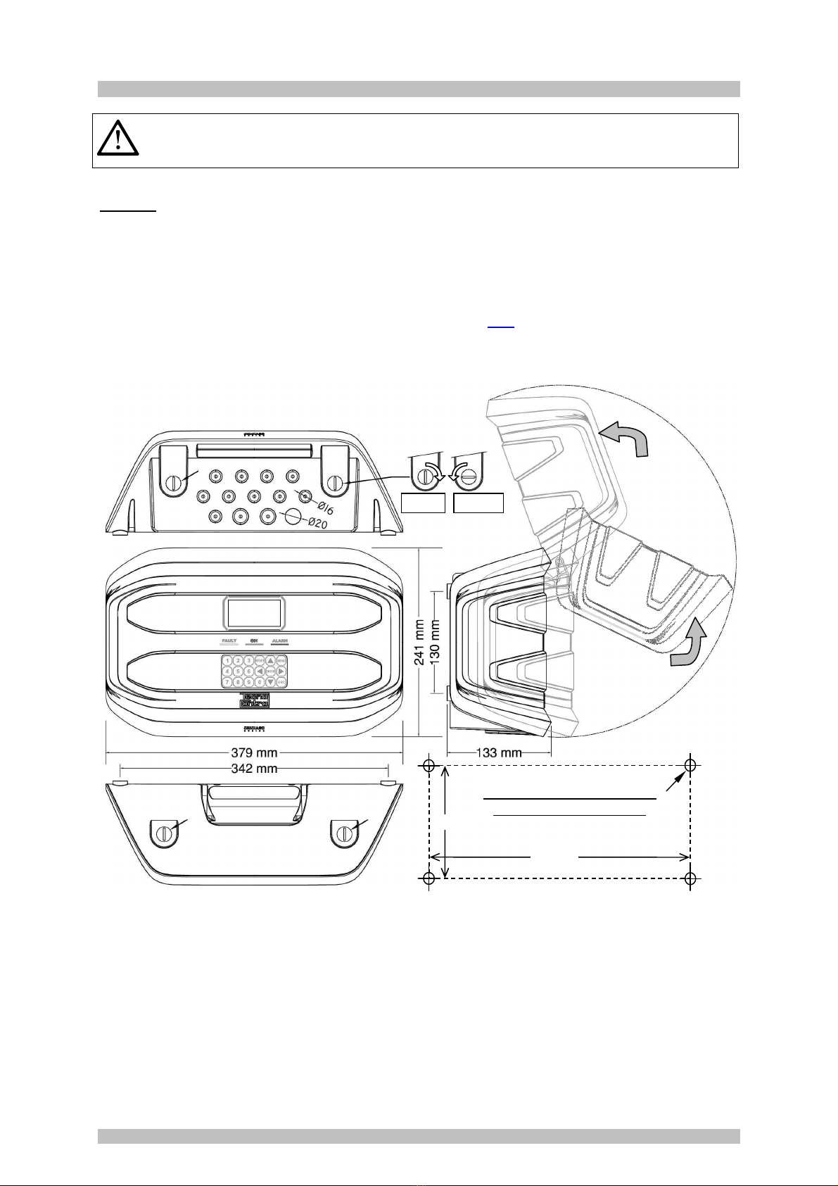
POSITION: The CE424P should be mounted on the wall using 4 screws and wall plugs (Ø 6 mm) or 4
M4 screws and nuts, if the wall is not in masonry. The housing's base must be fixed through the 3
holes, one in the center and the other in the bottom corners (Fig 2). The electrical connections should
be executed all on the housing base.
OPENING-CLOSING THE HOUSING
The housing has two sliding internal hinges. To open the case, you must:
1- With a coin or screwdriver (blade 10-12 mm), unlock the 4 closing buttons, turning them 90 °
clockwise.
2- Gently, pull the cover outwards of about 4 cm and then rotate it up and place it on the upper edge
of the base housing, in this way remain in the open position.
3- To close the housing act in reverse order. Pay attention that the cover and the locking mechanism
enter into place. Finally block 4 buttons, turning 90 ° counterclockwise. To facilitate the closure,
press on the lid, the buttons, which are eccentric, will bring the lid to adhere to the gasket.
OPENS
CLOSES
Fig 2 – CE424P Dimensions and Template fo wall mounting
The cover unlocks (with a coin) by turning 90° the 4
buttons located above and below the enclosure. t is
opened by pulling and then rotating it up until it rests at the
base.
342 mm
TEMPLATE FOR WALL MOUNTING
4 holes for wall plugs Ø 6mmn.
130 mm
IST-1424.CE02.02 CE424P / User Manual Pag. 9/50
TECNOCONTROL S. .l. - Via Miglioli, 47 20090 SEGRATE (MI) - Tel. 02. 26 92 28 90 - Fax 02. 21 33 734
ELECTRICAL CONNECTIONS
The electrical connections should be executed all on the housing base.
The details of the connections to the mains, the two batteries, the AUX input and relay output
R9 are illustrated in Figure 3
While the details of the connections to the sensors and the other
outputs are illustrated in Figure 4.
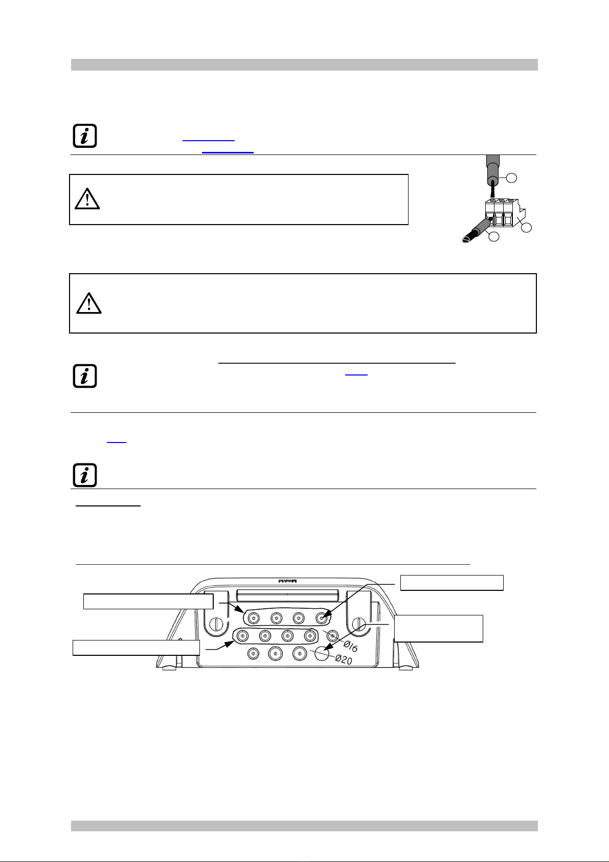
The terminals are of "polarized inlet" type (1). We suggest to use
lugs adequate to the conductors (2) and to fix the wires to the box
structure to avoid excessive stress to the circuits and to the
terminals. Use a screwdriver (3) with the right dimensions.
Considering that, it should be normal procedure disconnect power to the electronic equipment when
installing, or changing the connections, or when disconnecting or connecting expansion cards.
IMPORTANT: TO AVOID IRREVERSIBLE DAMAGE, DISCONNECT THE POWER
SUPPLY TO THE CONTROL PANEL, MAINS POWER AND BATTERY (IF PRESENTS)
DURING INSTALLATIO (WIRING CABLES) OR BEFORE YOU INSTALL ANY
EXPANSION BOARDS OR UNPLUG OR RE-CONNECT THE FLAT CABLE.
Only if necessary, for maintenance or installation requirements
, the housing cover can be
separated from its base, first remove mains power and remove the batteries
, then disconnect
the flat cable, press on the two side tabs as shown in Fig 3.
Then you need to release the cover
from sliding hinges (press fit). To reconnect it, proceed in reverse order and after hanging up
the lid hinges, push the flat cabl
e into the connector, respecting the polarization, the two levers
close automatically locking it. Only then you can reconnect power supply.
BATTERIES: Inside the housing, it can also accommodate two 2V/ .3Ah Lead batteries connected in
series (Fig 3) to assure the system powering in case of mains blackout. The battery life is about 30
minutes with 8 sensors. (The batteries are not included in the delivery, but are available on request).
f required, to increase the autonomy (6 hour), it can be used two 7Ah batteries connected in
series, but causes the greatest dimension, shall be installed in a case outside the CE408P.
Cable glands: the lower side of the housing has 13 inputs designed for metric cable glands (ISO
pitch 1.5 mm). N.10 are for glands M16x1.5 mm (that accept external cables Ø 4÷8 mm) and n.3 are
for glands M20x1.5 mm (that accept external cables Ø 6÷12 mm).
These passages are closed, but they are not manually breakable, according to the installation
requirements, they must be drilling. To facilitate the operation, they have a centering for the drill bit.
Please, pay attention not touch the tip of the internal circuits or the power supply cables
Center for the drill bit
Input fot Detector 5 to 8
Input fot Detector 1 to 4
Mains power
supply Input
3
1
2
Input terminal,
plug-polarized
IST-1424.CE02.02 CE424P / User Manual Pag. 10/50
TECNOCONTROL S. .l. - Via Miglioli, 47 20090 SEGRATE (MI) - Tel. 02. 26 92 28 90 - Fax 02. 21 33 734
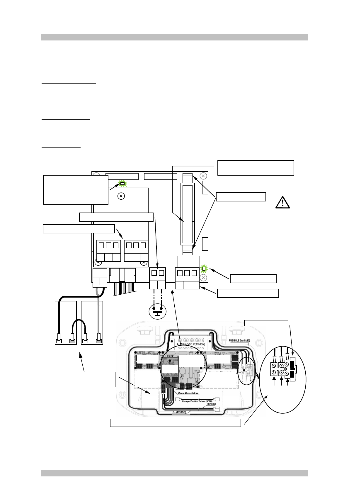
POWER CONNECTION
The installation must include a power line protection device. To the mains line, a bipolar disconnecting
switch dedicated for the gas detection system. The device, clearly identified, must act only on Phase
and Neutral, but not on the Earth. It is advisable to also provide for a surge protector, lightning etc.
Mains Power Supply (90÷264Vdc / 47÷63Hz) should be connected to terminal L, N and Earth at the
right of the housing base. The terminal has a protective fuse (5x20) 2A.
The two 12V/1.3Ah Lead batteries if required should be connected in series to BAT+ (Red) and BAT-
(Black) terminals. For the series connection, use the black cable supplied with two terminals (4.8 mm
Fastens).
The auxiliary input (AUX) can be used to connect devices with a NO or NC contact (gas sensors with
relay contacts, smoke sensors, buttons, etc.). It can be configured to activate one of the available
relays. It can be connected to multiple devices if it’s are homogeneous. (If the device has an NC
contact must be connected in series or in parallel if it’s have all a contact NO).
Output Relay 9 has the same characteristics and use of those described on the next page.
B
B+
B
-
NC
C NC
A A
B-
Nero
Black
Noir
B+
Rosso
Red
Rouge
Relay 9 output terminal
LEd: OUT 9 = ON
Press to Open
Fig 3 – CE424P Wi ing diag am fo Powe
,
Batte ies, AUX input and output 9.
Linea
Te a
Neut o
- + - +
Fuse
(5x20) 2A
90÷ 264 Vac / 47÷63Hz Mains power supply terminal
GND
L
H
GND
L2
H2
Auxiliary Input Terminal AUX
LED: Batt TEST ON
The LED lights up when
checking functioning of
batteries (if installed)
RS485 board (COM e COM2)
TO AVOID IRREVERSIBLE DAMAGE,
DISCONNECT THE POWER
SUPPLY TO
THE CONTROL PANEL, M
AINS POWER
AND BATTERY (IF PRESENTS)
BEFORE
YOU UNPLUG OR RE-
CONNECT THE
FLAT CABLE.
Flat-cable connector for cover
connection
n.2 Batterie 2V / .3Ah
Connected in Series
Outputs board
(Relays ÷4)
Inputs board
( ÷4)
Position Expansion
board
ES4 4 (Relays 5÷8)
Position
Expansion board
ES404
(Inputs 5÷8)
Main Board
Input AUX and
Outputs Relay 9
Outputs
RS485
Battery
n.
Battery
n. 2
IST-1424.CE02.02 CE424P / User Manual Pag. 11/50
TECNOCONTROL S. .l. - Via Miglioli, 47 20090 SEGRATE (MI) - Tel. 02. 26 92 28 90 - Fax 02. 21 33 734
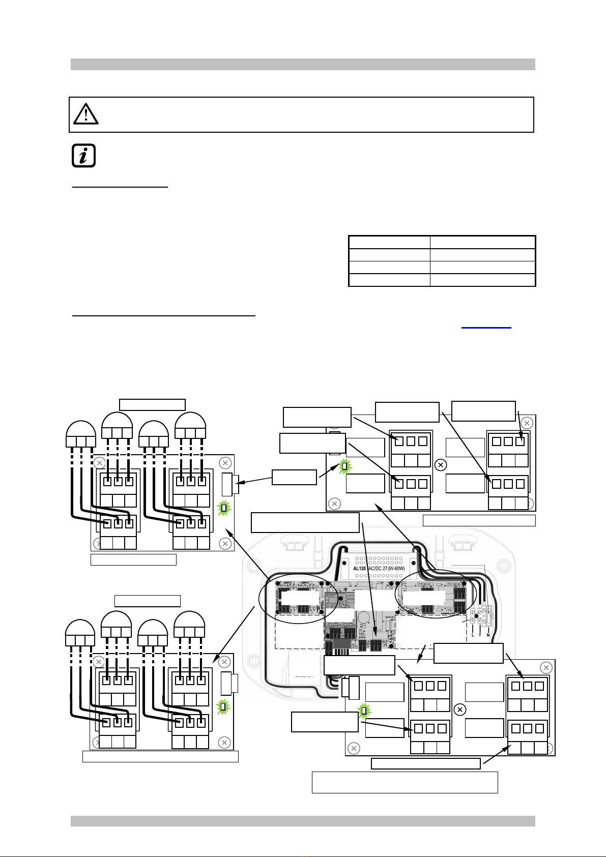
CONNECTION WITH GAS DETECTORS
Please efe also to the specifics
Use ’s Manuals enclosed with the Gas
Detecto s and the Remote Units.
Please note, that the CE424 has a board with 4 inputs and a board with 4 outputs. n Central
can be installed, a board ES404 and ES414 to have a total of 8 inputs and 9 outputs. The
diagrams, for simplicity, show all the 8 detectors and all relays outputs.
Detectors connection, (f om 1 to 8) with three-wire 4÷20mA transmitters, should be performed on the
inputs board, mounted in the base, on the left. The input terminals, “+, - and “S” should be connected
to the corresponding terminals of the sensor.
The connection of the other detectors (9-24) should be carried out into Remote Unit (please, see the
specific instructions).
The connection wire section between the CE424 and the
sensors should be suitable to the distance, as shown in the
table. The connection needs a shielded cable. (Cables for
control and signaling with shielding copper braid). Shield
should be connected only to the central unit side, and on an
only point of EARTH that has to be equipotential.
The connection to the internal outputs (elays 1 to 9) should be performed on the outputs board,
mounted in the base, on the right. The relay output 9 is located on the central board, see Figure 3 The
nominal load of relay is 250 VAC - 2 A or 30 VDC – 2 A (resistive load).
The relay have changeover free voltage contacts, on the boards, indications NA means NO (Normally
Open), NC (Normally Closed), C (Common), refer to the relays in the normal position (not powered). If an
output is configured as POSITIVE LOGIC, the NO contact will become NC and NC will become NA.
The connection of the other outputs ( elays 10÷25) should be carried out into Remote Unit (please,
see the specific instructions).
D
istan
ce
Cable
Max 200 meters 3 x1 mm
2
shielded
Max 400 metri 3 x 1.5 mm
2
shielded
Max 600 metri 3 X 2.5 mm
2
shielded
+
S
-
+
S
-
+
S
-
+
S
-
S1
+
S
-
S2
+
S
-
S4
+
S
-
S3
+
S
-
Input board ÷4
Outputs board with relays ÷4
ES404 Expansion board with inputs 5÷8
NA
C
NC
NA
C
NC
NA
C
NC
NA
C
NC
Terminal
of
Relay
Output no.
Terminal
of
Relay
Output no.2
Terminal
of
Relay
Output no.3
Terminal
of
Relay
Output no.4
+
S
-
+
S
-
+
S
-
+
S
-
S5
+
S
-
S6
+
S
-
S8
+
S
-
S7
+
S
-
Led: ON
Fig 4 – CE424P Wi ing diag am fo Inputs
Senso 4 to 20mA and elay Outputs
ES4 4
-
Expansion board with relays 5÷8
NA (in Italian) means NO (normally open)
NA
C
NC
NA
C
NC
NA
C
NC
NA
C
NC
Terminal
of
Relay
Output no.5
Terminal
of
Relay
Output no.7
Terminal
of
Relay Output
no.
8
Gas Detectors
Gas Detectors
Outputs board
(Relays ÷4)
Inputs board
( ÷4)
Position Expansion
board
ES4 4 (Relays 5÷8)
Position
Expansion board
ES404
(Inputs 5÷8)
Main Board
Input AUX and
Outputs Relay 9
Outputs
RS485
Battery
n.
Terminal
of
Relay
Output no.6
Terminal
of
Relay Output
no.9
Vedi / See / Voir Fig 4

IST-1424.CE02.02 CE424P / User Manual Pag. 12/50
TECNOCONTROL S. .l. - Via Miglioli, 47 20090 SEGRATE (MI) - Tel. 02. 26 92 28 90 - Fax 02. 21 33 734
L
GND
H
CE380UR no.2
Dip-Switch - Address
of Remote Unit 2
1 8
ON
OFF
U
NUSED
PORT RS485
L
GND
H
CE380UR no.1
Dip-Switch - Address
of Remote Unit
1 8
ON
OFF
U
NUSED
PORT RS485
GND
L
H
GND
L2
H2
COM2 RS485
COM RS485
L
GND
H
CE380UR no.2
Dip-Switch - Address
of Remote Unit 2
1 8
ON
OFF
U
N
USED
PORT RS485
L
GND
H
CE380UR no.1
Dip-Switch - Address
of Remote Unit
1 8
ON
OFF
U
NUSED
PORT RS485
Fig 5 – CE424P Remote units Connection with 4 to
20mA detecto s input and output elays.
Examples o connecting units to both ports (above) or to a single port (below).
RS485 outputs board (COM and COM2)
Detectors
Inputs
( to 4)
Outputs
RS485
COM1
COM2 ES4 4 Card outputs
(Relay 5 to 8)
Outputs
(Relay to 4)
ES4
04
Card inputs
(5 to 8)
AUX
input
and Output
relay 9
FUSE
GND
L
H
GND
L2
H2
COM2 RS485
COM
RS485
LED Rx/Tx
COM 2
LED Rx/Tx
COM
IST-1424.CE02.02 CE424P / User Manual Pag. 13/50
TECNOCONTROL S. .l. - Via Miglioli, 47 20090 SEGRATE (MI) - Tel. 02. 26 92 28 90 - Fax 02. 21 33 734
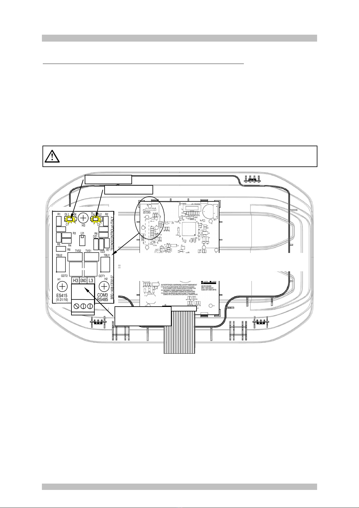
EXPANSION BOARD ES4 5 – MODBUS
The connection to a monitoring system via Modbus RTU binary protocol (COM3) is carried on the
optional expansion board ES415 (PC-Card Modbus output).
The ES415 board is mounted on the main board, placed in housing cover. (See Figure 6). Pay
attention, to put the terminals into the connector on the motherboard, making the first, matching the
three click columns with the corresponding holes and then pressing to insert them.
The "H3 (D1)", "GND (Common)," and "L3 (D0)" terminals of the RS485 serial port (COM3) are to be
connected to the supervision system (Master) or dedicated isolated converter (not included).
On standard MODBUS system, all devices are connected (in parallel) on a distribution cable with 3
shielded wires. Two form a balanced pair of twisted conductors, on which the bidirectional data,
typically at 9600 bits per second are transmitted. The third conductor (if used) is the common to all of
the bus devices.
To avoid irreversible damage, disconnect the power supply to the control panel, Mains
power and Battery (if presents) before you unplug or re-connect, any expansion card.
Fig 6 –
CE424P Expansion ca d ES415 with COM3 (RS485)
Modbus se ial po t.
LED Tx COM 3
LED Rx COM 3
Te minal
COM 3 RS485-
Modbus
Card location (Internal housing cover opened up)

IST-1424.CE02.02 CE424P / User Manual Pag. 14/50
TECNOCONTROL S. .l. - Via Miglioli, 47 20090 SEGRATE (MI) - Tel. 02. 26 92 28 90 - Fax 02. 21 33 734
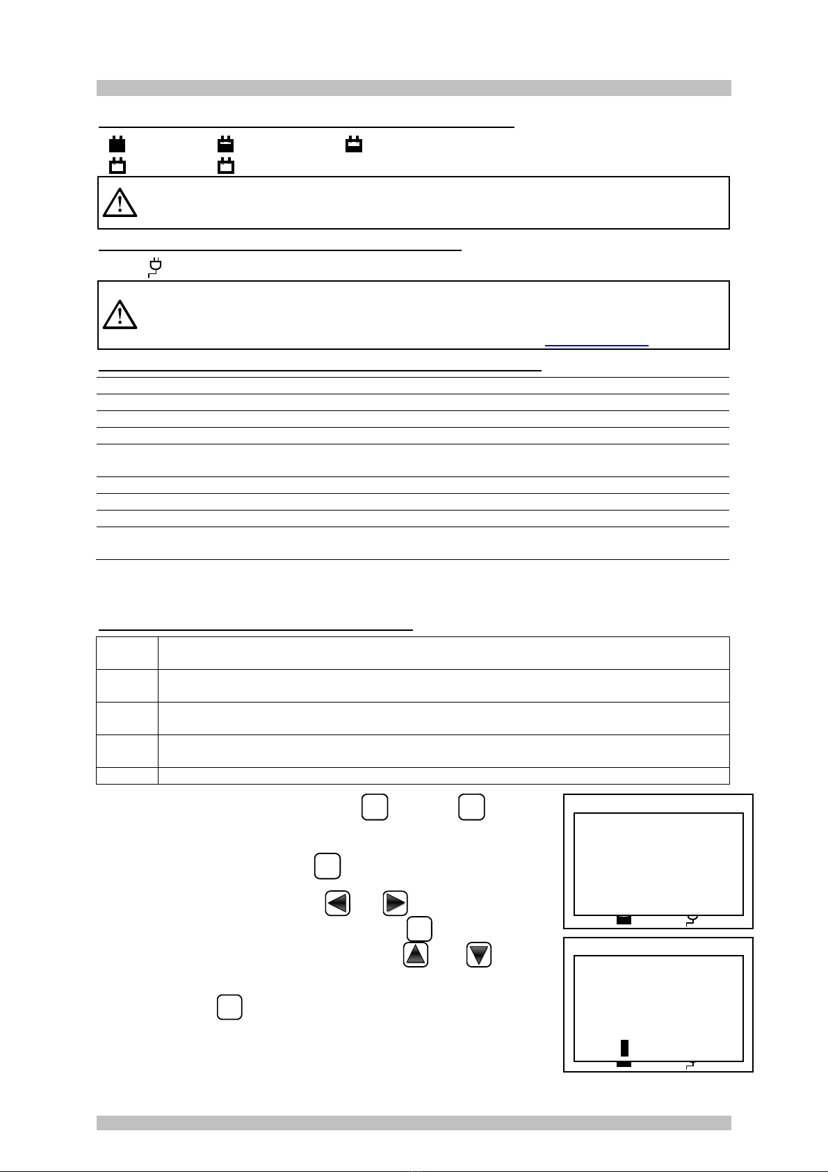
UNIT’S OPERATION
Keyboard:
The keyboard is backlit. To save energy, the brightness is reduced to half after 10 seconds of non-use.
RESET
Can only be used on the main screen, it is used to reset the latched outputs to normal
operation, but only if the Sensor or Zone or Input has returned from the alarm condition. If
there are active alarms, outputs configured as Silenceable (e.g. alarm) returns to normal
operating conditions only for the time of silencing by default.
Scroll through the display screens and the numeric digits up and down.
Keeping the key pressed, increases the values' speed scrolling. In the main screen
changes to display the status of sensors, inputs and configured zones.
MEN
Ù
Call up the Main Menu from any screen.
ENTER
Confirm the inserted data and in the main screen allows you to select the detail’s sensors
Scroll through the pages (6 sensors at a time and events at a time), and input fields.
Keeping the key pressed, increases the speed scrolling.
ESC
Cancel an operation and in the main screen is used to enter to Main Menu
0
÷
9
They insert a number directly into numeric fields and recall the related submenu in the
specific screens. Also in the main screen, key
0
recalls a brief screen of the alarm’s
status (see below).
• Single digit numeric field (password entry, etc )
By pressing a numeric key the number is displayed in the field.
• Screens 'Enable ', 'Disable ', 'Copy ', 'Delete ', 'Settings-> Date & Time':
Pressing the first time, a numeric key the number is displayed in its field (deleting any existing
number), and the next digits will be always inserted to the right of the number.
Example: To enter the number "23", press the
2
and then
3
.
If the number exceeds the maximum acceptable value, message
will appear "PARAMETER OUT OF RANGE". ------------------------- >
• All other Screens:
As above, but in addition, when you press the
key, the last
digit entered will be erased and you can continue to enter
additional digits.
Example: If you have entered the number "23", and then you want to change it to "25", simply
press the
then press the
5
key.
If you have already entered a single digit, pressing
will display the minimum amount
accepted by the field. Then, by pressing a number key, the number already present is deleted
and replaced with the new one.
Fig 5 – CE424P Keyboa d
Keyboard
Display
LEDs
PARAMETER
OUT OF RANGE

IST-1424.CE02.02 CE424P / User Manual Pag. 15/50
TECNOCONTROL S. .l. - Via Miglioli, 47 20090 SEGRATE (MI) - Tel. 02. 26 92 28 90 - Fax 02. 21 33 734
LED indications
The CE424P has 3 LEDs, which show the status of unit operation (see also Appendix).
FAULT
(Yellow LED)
Flashing = Preheat (Start Unit) or Firmware Update.
Fixed ON = Fault (Sensor) + Buzzer if enabled.
Short flashing = Output relay associated with a latched Fault.
Rapid flashing = Batteries Fault.
ON
(Green LED)
Fixed ON = Operation with mains power.
Flashing = Operation with the batteries.
ALARM
(Red LED)
Fixed ON = Alarm 3 is active (Sensor or Zone) + Buzzer if enabled.
Flashing = Alarm 1 and / or 2 active (sensor or area or logic input).
Short flashing = alarm latched (indented) (sensor or area or logic input).
Display Backlight Indications
The CE424 has the display (backlight) that changes colours depending on the state of operation of the
plant (see also Appendix).
YELLOW Fault (
Detector or Zone or Remote Unit
) or fault memorised
CLEAR BLUE No active alarm.
LIGHT RED Alarm memorized (indented) (
Detector, Zone or logic input
).
MEDIUM RED Alarm 1 and / or 2 active (
Detector or Zone or logic input
).
BRIGHT RED Alarm 3 is active (
Detector or Zone
) or Firmware updating is in progress
Internal Buzzer Indications
The CE424 has an internal buzzer that emits a beep when a key is pressed. It can also be
configured to sound in the event of a fault and / or an alarm.
Sound short (0 1s) is always active Confirms the pressing of a key
Continuous sound if configured Fault (Sensor or
Zo
ne)
Continuous sound if configured Alarm 3 is active (Sensor or Zone)
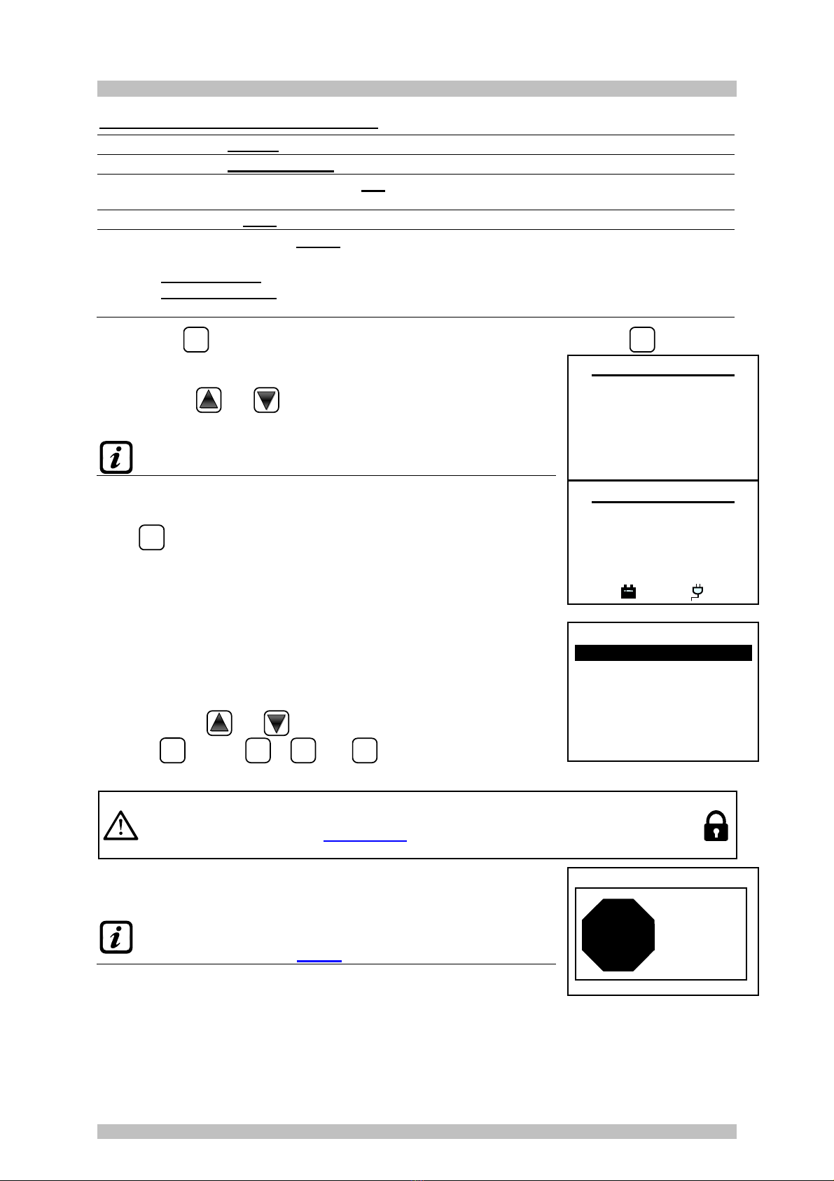
Display – Initial Screens
The CE424P when powered, for 5 seconds shows the model name and
firmware version. -----------------------------------------------------------------------
This information shall be accessible also in the menu
Settings
General
Info
For more information read the chapter Settings.
Only at fi st powe (and only then) will be asked to
choose your
language and to indicate if the battery is present. Use the key
and
to scroll through the languages and pressing
the
key
ENTER
to confirm the choice. ------------------------------------------
From this screen, you cannot go out without being made a
choice.
f necessary, these choices can be changed. Please see forward
Service
Battery
. For more information read the chapter
Service...
After starts a decreasing count of 60 seconds, the time required to boot
the central unit, and allow the sensor to stabilize (preheating time). ----
After the preheating time, appears the main screen that the control unit
displays in normal operation. The date is shown in the top row, the first 6
sensors (with the measured concentration and its state) and in the last
line, the battery status of charge (if installed) and presence of the mains:
The number in the lower left corner indicates the current access level
(level 0 if it is blank). The word “SD” on the bottom right indicates active
the data storage.
CE424 ve .
1.0x
LINGUA
-
LANGUAGE
LANGUE
1 ITALIANO
2 ENGLISH
3 FRANÇAIS
4 ESPAÑOL
PRESENCE
BATTERY
1 NO
2 YES WAIT
60
12:00 f i
04/11/2016
1) 2% LEL NORM
2)10.2 ppm AL.1
3) 300 ppm AL.3
4) - - - -
5) - - - -
6) - - - -
2¯¯¯¯¯ ¯¯¯¯¯¯¯ ¯¯¯¯SD
IST-1424.CE02.02 CE424P / User Manual Pag. 16/50
TECNOCONTROL S. .l. - Via Miglioli, 47 20090 SEGRATE (MI) - Tel. 02. 26 92 28 90 - Fax 02. 21 33 734
Symbols used to indicate the status of the battery (if installed):
= Full charge = Half charge. = Low charge
= Discharge Flashing = Fault.
f by mistake, the battery (configured present) being disconnected and / or connected with the
control unit power from mains, the yellow LED lights up on fast blinking, to resume the normal
operation of the battery, it will be necessary turn off and on the unit.
Symbols used to indicate the presence of mains power:
= mains operation (is absent, when the power is by the batteries).
If the control unit, had lost the date and time, due to a malfunction or discharge of
the clock
backup battery, screen will be displayed for entering updated values (
The unit's safety
functions are guaranteed, except those involving the use of date that will be wrong). By
changing these parameters, see below, the section SETTINGSDATE and TIME
The status of a sensor, which appears on the main screen, may be:
-
-
-
-
not Configured
The Sensor (detector) is not Configured
* * * *
disable
The Sensor is disabling. (
the outputs (relay)
ar
e not activated i
an alarm occurs
)
OFF LINE
UR
not conncted
The detector connected to a remote unit that is not connected.
FAULT
Guasto
input current is less than 1mA
NORM. Normal There is no gas and there are no active alarms. The text blinks when relay
output is latched (Sensor or Zone, returned to normality after an alarm or a fault).
AL.1
Allarm 1
The first alarm threshold has been exceeded
AL.2
Allarm 2
The second alarm threshold has been exceeded
AL.3
Allarm 3
The third alarm threshold has been exceeded.
F.S. Full Scale Current > 24 mA. The gas concentration has exceeded the Sensor range
or the sensor may be faulty.
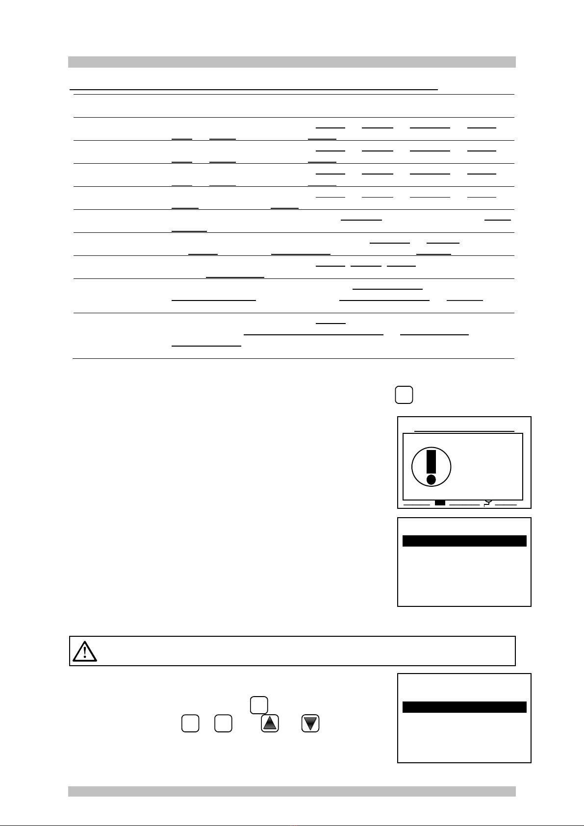
When a sensor, a logic input or a zone, activate a relay output, the main screen appears a brief
display of alarm status. This allows checking quickly, the total number of active relays and their
relative alarm level.
The details of the individual items is as follows:
FAULT
Indicates the number of active relays, relative to exceeding the threshold of a fault (current
<1 mA or> 24 mA), of a sensor or a group of sensors that belong to a zone.
AL. 1
Indicates the number of active relays, relating to exceeding the threshold of alarm 1, of a
sensor or a group of sensors that belong to a zone.
AL. 2
Indicates the number of active relays, related to exceeding the threshold of alarm 2, of a
sensor or a group of sensors that belong to a zone.
AL .3
Indicates the number of active relays, relating to exceeding the alarm threshold 3, of a
sensor or a group of sensors that belong to a zone.
INPUT
Indicates the number of active relay, logic input.
The screen can be closed by pressing the
ESC
key or the
RESET
key. If the
alarms persist the screen reappears after 10 minutes. If a new alarm
occurs the screen will appear again automatically. You can call the
screen at any time by pressing the
0
key on the main screen. ---------
From the Main screen, by pressing
and
keys, to scroll through
the sensors, in groups of 6 at a time. Pressing
ENTER
key highlights the
sensor in the first row. While, using the keys
and
to scroll
through the sensors (in the page) shown on the display.
Pressing the key
ENTER
again, you view the details of the highlighted
sensor, (of course only if it is configured). ---------------------------------------
12:00
f i
04/11/2016
¯¯¯¯¯¯ ¯¯¯¯¯¯¯ ¯¯¯¯¯
N.
1
GAS: METHANE
2%LEL 05.60mA
ZONE:0
OUTPUT:
0 1 2 9
12:00 f i
04/11/2016
¯¯¯¯¯¯ ¯¯¯¯¯¯¯ ¯¯¯¯¯
ALLARMS STATUS
FAULT: 00 AL 1: 01
AL 2 : 00 AL 3: 03
INPUT: 00
Press Reset/Esc
IST-1424.CE02.02 CE424P / User Manual Pag. 1 /50
TECNOCONTROL S. .l. - Via Miglioli, 47 20090 SEGRATE (MI) - Tel. 02. 26 92 28 90 - Fax 02. 21 33 734
Explanations of the details are as follows:
1
st
ow shows the numbe of the sensor
2
nd
ow shows the name of the gas being measured.
3d ow shows the currently measured gas concentration, the unit of measure and current
value
(mA) (current generated by the sensor).
4
th
ow indicates the Zone
6th ow
• the indicates the output number (Relay), corresponding respectively to:
1st Th eshold (AL1) 2nd Th eshold (AL2) 3 d Th eshold (AL3) FAULT.
Value 0 (ze o) indicates, at that threshold, the output not been assigned, while
the
highlighted value indicates that output relay is currently active (alarm). The values are
real
time updated.
Pressing the
ESC
key it returns to the screen of the sensors. Then press again the
ESC
, to return to
the Main Screen
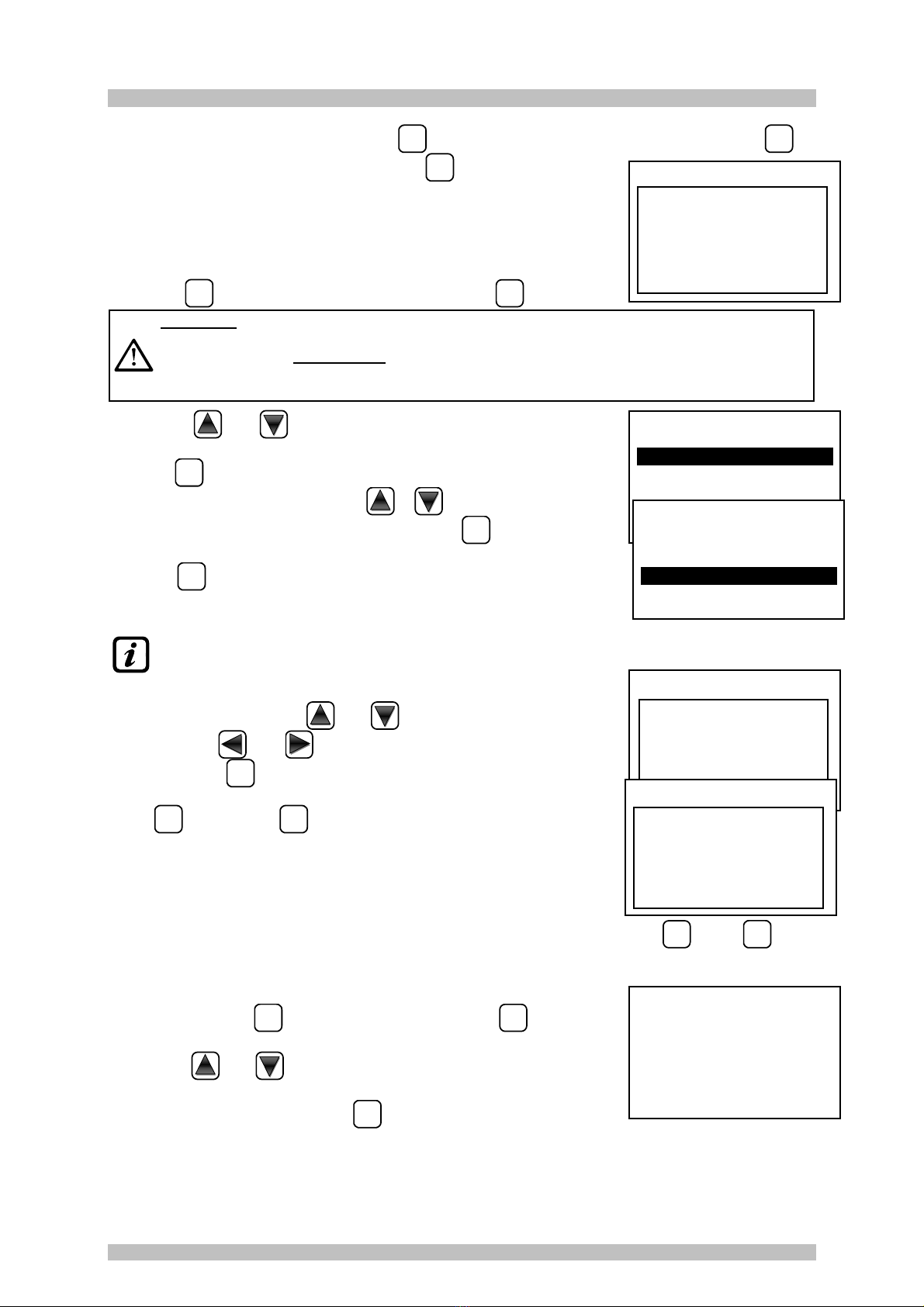
Using the keys
and
is displayed, in cyclic mode, the situation of
the Zones (from Z1 to Z6) and the Logic Input AUX (I1). --------------------
Note that the model CE408P has only 2 Zone and 1 Logic nput
The status of a logic input can only be ACTIVE or DEACTIVE, while a
Zone has the same status of a sensor, except for the full-scale. ----------
Press
ESC
to enter the Main Menu.
MAIN MENU
The CE424 is provided with a main menu from which you can manage all
of its functions.
The name of each line indicates the thematic area on which we can take
action, by accessing the corresponding submenus. ---------------------------
Pressing the key
and
to scroll through the menus.
Pressing
ENTER
or keys
1
.to.
9
and
0
to enter the corresponding
submenus.
Some submenus have an access level (Password) indicated by the symbol "lock
"
visible when the level was not enabled. To enable it, you must enter the specific
password, as shown in Access menu. Carried out the enabling, the "locks
" of the
enabled level disappear.
If you try to enter a submenu without entering the password, the access
is denied. A higher access level also enables the lower one. ---------------
The required access level is indicated, when necessary, to the left
of the individual items of the manual. To enable them, with the
password, see the menu Access
SENSORS
7
DETAILS
LEVEL NOT
ENABLED
ACCESS
DENIED
P ess Esc
STOP
CE408
1 RESET
2 REMOTE UNITS
3 SENSORS
4 INPUTS
5 ZONES
6 EVENTS
7 SETTINGS
12:00
f i 04/11/2016
Z1) NORM.
Z2) - - - -
Z3) - - - -
Z4) - - - -
Z5) - - - -
Z6)
-
-
-
-
12:00 f I 04/11/2016
I1) LOW DEACTIVE
¯¯¯¯
¯
¯¯¯¯¯
¯¯¯¯
IST-1424.CE02.02 CE424P / User Manual Pag. 18/50
TECNOCONTROL S. .l. - Via Miglioli, 47 20090 SEGRATE (MI) - Tel. 02. 26 92 28 90 - Fax 02. 21 33 734
List and short description of the accessible menus and the required Password:
1-RESET Performs silencing or Resetting the alarms and faults, not active and return to
the main menu.
2- REMOTE UNITS Enter a submenu where you can enable , disable , configure , modify ,
copy , delete and view the details of the remote units.
3-SENSORS Enter a submenu where you can enable , disable , configure , modify ,
copy , delete and view the details of the sensors.
4- INPUTS Enter a submenu where you can enable , disable , configure , modify ,
copy , delete and view the details of the logic input.
5-ZONE Enter a submenu where you can enable , disable , configure , modify ,
delete and view the details of the zones.
6- EVENTS Enter a submenu where you can view, all events or ones related only to faults
/ alarms.
7- SETTINGS Enter a submenu where you can change, the language , general settings,
the buzzer settings , date and time and settings the Modbus protocol.
8- ACCESS MENU Enter a submenu where you can enable, disable, modify, the password, of the
relative access levels .
9-SERVIZIO
Enter a submenu where you can perform electrical testing of the control unit
manage the battery and display the status of the sensors . Start-Up is not
accessible.
0-SD CARD
Enter a submenu where you can update the Firmware of the control panel
via an SD Card, upload or save the configuration , save the events or
store the values read by the detectors (Detectors’ data logger) on the SD
card (if inserted).
RESET
The RESET item in the main menu, performs the same function as the
RESET
key, reset the latched
outputs to normal operation, but only if the Sensor or Zone or Input has returned from the alarm
condition.
If there are active alarms, outputs configured as Silenceable (e.g. an
alarm) return to normal operating conditions only for the time of
silencing.
When performing the RESET (with key or from the menu), the display
shows the confirm message for about 3 seconds, then the previous
screen reappears automatically. ---------------------------------------------------
REMOTE UNITS
In this submenu you can manage remote units connected to the central
unit. ----------------------------------------------------------------------------------------
Below, the individual items are described in detail, with the same level
password, which is indicated in parentheses.
RU ENABLE/DISABLE (Level 1): These two items allow you to enable or disable one or more
remote units, even simultaneously.
The disabled RU, no longer trigger the alarm and fault outputs, associated with them (
the
outputs remain in a state of normal operation, and then the alarms associated with them are not triggered).
On the main screen, the symbol “*****” appears to the left of the sensors
belongs to the Remote Unit disabled.
To enable or disable a RU press the
ENTER
key on the relevant item,
highlighted or using keys
1
or
2
. With
and
it is possible to
select, if you take action on a single RU (first line) or on a group of RU
(second line). ----------------------------------------------------------------------------
UNITÀ REMOTE
1 ENABLE
2 DISABLE
3 CONFIGURE
4 COPY
5 MODIFY
6 DETAILS
ENABLE
REM. UNIT N.
FROM N. TO N.
12:00 f i 04/11/2016
¯¯¯¯¯¯
¯¯¯¯¯¯¯
¯¯¯¯¯
RESET
PERFORMED

IST-1424.CE02.02 CE424P / User Manual Pag. 19/50
TECNOCONTROL S. .l. - Via Miglioli, 47 20090 SEGRATE (MI) - Tel. 02. 26 92 28 90 - Fax 02. 21 33 734
Pressing
ENTER
on the first line, will highlight the number of the RU. Then
you choose the desired number, with
and
or using the numeric
keys and then pressing
ENTER
the confirmation window will appear.
Pressing
ENTER
on the second line, will highlight the first RU’s number of
the group. --------------------------------------------------------------------------------
You can enable or disable
all RU, including between two, both from the smallest to the largest
number, and the reverse, f the two numbers of sensors were equal, the effect is identical to
the management of a single RU.
With
and
or using the number keys, you can choose the
number of required RU, pressing
and
you change from one
value to another and then, pressing
ENTER
confirmation window will
appear. -----------------------------------------------------------------------------------
Press again
ENTER
to confirm or in case you want to go back, press
ESC
.
If the RU is not configured, a window notifies you that the operation is not
possible. ----------------------------------------------------------------------------------
Then the screen returns to the selection of the RU.
f you have selected a group of RU, the ones that have been configured are
enabled or
disable. Dialog box appears to warn you that you have selected one or more RU not configured.
If this procedure is correct, a window notifies you that the operation has
been successful. -----------------------------------------------------------------------
Then the screen returns to the beginning of the management for Enabled
or Disable the RU.
CONFIGURE (Level 2): To access the RU configuration, press
ENTER
on
its item highlighted or simply press key
3
.
Then you can choose the RU’s number to be configure, using
and
or the numeric key and pressing
ENTER
to confirm. ------------------------
With
and
you scroll through the various items and then
pressing
ENTER
on the item, the value is highlighted to indicate that it is
editable -----------------------------------------------------------------------------------
To change the value use
and
or the numeric keys. then
pressing
ENTER
l the change will be accepted. Pressing
ESC
will restores
the previous value and the entire row is selected, indicating that you can only scroll through the items.
Desc iption of items elated to the Remote Units:
REM UNIT: indicates the number of the RU installed. This number corresponds to the RU that must
be set with the DIP-Switches (please see the specific RU manual).
The central unit
considers configurable, the numbers of the sensors according to the number of
RU configured. The 1st RU manages the sensors from no. 9 to 16, the 2nd
RU those from 17 to
24. The same concerns the relay outputs (if any), the 1st RU controls the relays from
no. 10 to
no. 17, the 2nd RU those from no.18 to 25.
PORT: Sets the number of serial port which the RU is connected to. The control panel manages two
RS485serial ports, COM 1 and COM 2. Please enter the correct port number.
Please note that if the number of RU or the port is not correct, the RU will result out of line.
ABILITA
UN. REM N.
DAL N. AL N.
ENABLE
CONFIRM ?
YES = ENTER
NO = ESC
CONFIG. REM.UNIT
REM. UNIT N. 1
CONFIG. REM.UNIT
REM. UNIT N. 1
PORT COM 1
SAVE
ENABLE
REM. UNIT
N. 1
ENABLED
ENABLE
REM. UNIT
N. 1
NOT CONF.
IST-1424.CE02.02 CE424P / User Manual Pag. 20/50
TECNOCONTROL S. .l. - Via Miglioli, 47 20090 SEGRATE (MI) - Tel. 02. 26 92 28 90 - Fax 02. 21 33 734
Then move on the SAVE and pressing
ENTER
confirmation window will appear. Press again
ENTER
to
confirm or in case you want to go back, press
ESC
.
If this procedure is correct, a window notifies you that the operation has
been successful. -----------------------------------------------------------------------
Then the screen returns to the RU configuration.
DELETE (Level 2): This item allows you to delete a RU or a group of
RU. Press
ENTER
on the relevant item or simply press key
4
.
WARNING
: deleting a Remote Unit, will be deleted both all the sensors connected to it,
both the corresponding relay outputs, if installed
(RU no.1 OUT 10 to 18 and for the RU
n.2 OUT 19 ÷ 25) IMPORTANT: If these relays
were related to Sensors or Areas that do
not belong to the RU cancelled
, those outputs in the configuration will be set to 0 (no
relay), then the outputs of these sensors will have to be reconfigured
Then using
and
it is possible to select, if you take action on a
single RU (first line) or group of RU (second line). ----------------------------
Pressing
ENTER
on the first line, will be highlighted the number of the single
RU. Then with numeric keys or with
e
you choose the number
of RU you want delete, then pressing again
ENTER
will appear the
confirmation window.
Pressing
ENTER
on the second line, will be highlighted the 1st RU of the
group. -------------------------------------------------------------------------------------
You can delete all RU, between 2. Both from the smallest number
too largest, or the contrary. f two numbers, of zones were equal,
the effect is equal to management of a single RU.
With numerical keys or with
and
you choose the number of RU
you want, with
and
you can go from one extreme to another.
Finally, pressing
ENTER
the confirmation window will appear. -----------------
Press
ENTER
to confirm or
ESC
to go back. Each time you press it, you will
return to the previous step.
After confirmation, the window will notify that the operation has been
successful. -------------------------------------------------------------------------------
Then the screen returns the beginning of the management the deletion.
MODIFY (Level 2): this item allows modifying a RU already configured. Press
5
key or
ENTER
on its
item. The parameters are modified and saved in a similar way to the configuration of the RU.
DETAILS: This item allows you to see parameters of a RU already
configured, pressing
ENTER
on its item or simply press key
6
. ------------
The voices are the same as the RU configuration. You can scroll through
them using
and
. The status of the RU is indicated at the end of
the screen: P esent or Out of Line or Disabled.
In case you want to go back, press
ESC
.
DELETE
CONFIRM ?
YES = ENTER
NO = ESC
REM. UNIT DETAILS
REM. UNIT. N. 1
PORT N. 1
STATUS : PRESENT
DELETE
REM. UNIT N.
FROM N. TO N.
DELETE
REM. UNIT N.
FROM N. TO N.
DELETE
REM. UNIT N. 1
DELETED
CONFIG. REM.UNIT.
REM. UNIT
N. 1
CONFIGURED
Table of contents
Other Tecnocontrol Control Unit manuals


Popular Control Unit manuals by other brands


Bray
Bray TRI LOK Installation, operation & maintenance manual

Digi
Digi XBee3 802.15.4 user guide

Mitsubishi Electric
Mitsubishi Electric MELSEC Q Series user manual

Armstrong
Armstrong 320 Installation and Maintenance

Interlogix
Interlogix UltraSync UM-Z8 Installation sheet

Sierra Wireless
Sierra Wireless mangOH Green DV4 user guide