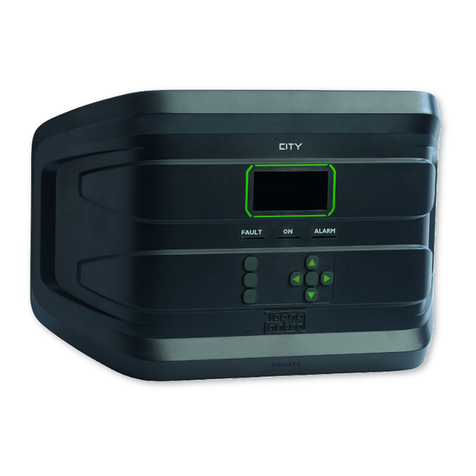
Tecnocontrol SE293K User manual

IST-2293.KM01.01 Istruzione / User’s Manual / Manuel d’utilisation Pag.1/9
(IST-2293.KM01.01_SE293K (09.11.2017).docx)
Centralina gas per 3 rilevatori remoti
Gas control unit up to 3 remote detectors
Centrale détection de gaz avec 3 sondes extérieures
TECNOCONTROL S.r.l. Via Miglioli, 47 20090 SEGRATE (MI) ITALY Tel. +39 02 26922890 Fax +39 02 2133734
http: www.tecnocontrol.it e mail: info@tecnocontrol.it
SE293K
Rilevatori collegabili all’SE293K
Dete tors whi h an be onne ted to the SE293K
Sondes ra ordables au SE293K
Modello
Model/ Modéle
Caratteristiche
Features/ Caractéristiques
SE192KM Metano/Methane – IP44
SE192KG GPL/LPG – IP44
SE193KM Metano/Methane - II 2G Ex d IIC T6 Gb
SE193KG GPL/LPG - II 2G Ex d IIC T6 Gb
SE183KM Metano/Methane - II 2G Ex d IIC T5 Gb
SE183KG GPL/LPG - II 2G Ex d IIC T5 Gb
Caratteristiche tecniche / Te hni al spe ifi ations / Cara téristiques te hniques
Alimentazione principale / Main power supply / Alimentation principale.
11 ÷24 Vac (-15/+1 %) 5 ÷6 Hz / 1 VA
Alimentazione a siliaria / Auxiliary power supply / Alimentation auxiliaire. 24VDC (-1 /+15%) / 12W
Rilevatore remoto / Remote detector / Sonde extérieure Catalitico / Catalityc / Catalytiques
Ingressi / Inputs / Entrées Max 3 / 4÷2 mA
Campo di misura / Standard Range / Champ de mesure ÷ 2 % LIE / LEL
1° Soglia di allarme /
st
Alarm threshold /
er
seuil d'alarme 1 o/or/ou 15 % LIE / LEL
2° Soglia di allarme / 2
nd
Alarm threshold / 2
eme
seuil d'alarme 2 % LIE / LEL
Contatti relè / Contacts rating / Contact relais 23 Vac 3A SPDT
Temperatura-Umidità di funzionamento
Operation Temp-Humidity / Temp. et humidité de fonctionnement
-1 ÷ +5 °C / 5 ÷ 9 % RH
non condensata / non condensed / non condensée
Pressione di funzionamento.
Operation Pressure / Pression de fonctionnement
Atmosferica ±1 %
Atmospheric±1 % / Atmosphérique ±1 %
Temperatura-Umidità di immagazzinamento
Storage Temp-Humidity / Temp. et humidité de stockage
-25 ÷ +55°C / 5 ÷ 95 % RH
non condensata / non condensed / non condensée
Grado di protezione / IP Code / Indice de protection IP65
Dimensioni / Size / Dimensions 2 2 x 153 x 1 4 mm
Peso / Size- Weight ,7 Kg
IT
DESCRIZIONE ........................................................................................................................... 2
FUNZIONAMENTO ................................................................................................................................. 2
INSTALLAZIONE .................................................................................................................................... 2
AVVERTENZE ........................................................................................................................................ 3
VERIFICA FUNZIONAMENTO ............................................................................................................... 3
EN
DESCRIPTION ........................................................................................................................... 4
OPERATIONAL DESCRIPTION ............................................................................................................. 4
INSTALLATION ...................................................................................................................................... 5
WARNING ............................................................................................................................................... 5
FUNCTIONAL TESTING ......................................................................................................................... 6
FR
DESCRIPTION ........................................................................................................................... 6
FONCTIONNEMENT............................................................................................................................... 6
INSTALLATION ...................................................................................................................................... 7
AVERTISSEMENT .................................................................................................................................. 8
VERIFICATIONS PERIODIQUES ........................................................................................................... 8
1: 0 2: 0
3:
off
%LEL

IST-2293.KM01.01 Istruzione / User’s Manual / Manuel d’utilisation Pag.2/9
TECNOCONTROL S.r.l. Via Miglioli 47 SEGRATE ( MI ) Tel: 02/26 92 28 90 Fax: 02/21 33 734
IT
DESCRIZIONE
L'SE293K è una centralina per centrali termiche, o ambienti da proteggere da possibili fughe dei gas, collegabile
fino a n.3 rilevatori remoti di tipo catalitico per gas infiammabili. Può essere collegata ai seguenti rilevatori remoti:
• Il Mod. SE192KM o SE193KM o SE183KM va utilizzato in impianti alimentati a Metano.
• Il Mod. SE192KG o SE193KG o SE183KG va utilizzato per quelli a GPL.
L'SE293K è per montaggio a parete e il grado di protezione è IP65. È alimentato a 11 ÷24 Vca / 5 ÷6 Hz ma può
essere collegato ad un’alimentazione esterna a 24Vcc (es. alimentatore con 2 batterie tampone collegate in serie
da 12V-7A/h tipo nostro modello PS18 /24VDC).
Sulla targa frontale sono visibili tre Led che indicano lo stato di funzionamento, il display che mostra la concentra-
zione di gas rilevata da ogni rilevatore remoto e due tasti funzione (TEST e RESET). La centralina è dotata di due livel-
li di allarme con uscite a relè di tipo sigillato normalmente eccitati con contatti in scambio liberi da tensione (ALARM1
e ALARM2). Inoltre è presente un’altra uscita relè in sicurezza positiva per le situazioni di guasto (FAULT).
La centralina ha due ingressi ausiliari. AUX1 per collegare dispositivi con contatto NA come ad esempio un Pulsante
manuale. AUX2 è l’ingresso per controllare le nostre Elettrovalvole a Riarmo Manuale NC con sensore di posizione.
In Fig.1 esempio di collegamento con 3 rilevatori remoti, sirena, elettrovalvola a riarmo e pulsante manuale.
FUNZIONAMENTO
Accensione: ogni volta che la centralina è alimentata, il display visualizza il nome del produttore, il modello e la
versione del firmware (es. Tecnocontrol srl / SE293K v.1.00).
Lingua: poi, sul display appare sempre la scelta delle lingue disponibili (es. IT-EN-FR) premendo il tasto RESET si
cambia lingua, premendo il tasto TEST si conferma la scelta. Se non si effettua la scelta entro 1 secondi, in auto-
matico il programma prosegue mantenendo l’ultima lingua selezionata.
AVVERTENZA: la scelta della lingua appare sempre ad ogni accensione, ma dopo 10 secondi il programma prosegue automaticamente
utilizzando l’ultima lingua selezionata.
Info: poi, appaiono sempre in sequenza 3 videate con il promemoria della configurazione impostata tramite i Dip-
Switch: SCALA DI MISURA / SOGLIE ALLARMI / SE SORI ABILITATI. Poi il programma prosegue automaticamente.
Preriscaldo: quando la centralina è alimentata, inizia la fase di preriscaldo, visualizzata sul display dal conteggio
decrescente di 6 secondi e dal lampeggio del Led giallo.
Funzionamento normale: al termine del preriscaldo, il display mostra il valore della concentrazione di gas e lo sta-
to dei rilevatori remoti.
Il Led Verde si accende fisso per indicare il normale funzionamento e la presenza di alimentazione.
Il Led Rosso (ALARM) si accende e lampeggia se la concentrazione di gas supera la 1° soglia di allarme configu-
rabile a 1 o 15 % LIE ed entro 5 secondi interviene il relè ALARM 1, che normalmente è utilizzato per comandare
una sirena (nostro mod. SE301A se alimentata a 230Vca o SE301B se alimentata a 24V).
Il display mostra il canale in allarme visualizzando alternativamente il valore e la scritta AL1.
Il Led rosso (ALARM) si accende fisso se la concentrazione di Gas supera la 2° soglia di allarme al 2 % LIE, se il
gas persiste, entro circa 3 secondi, interviene il relè ALARM 2, configurabile in logica positiva (normalmente eccitato) o
negativa. Normalmente il relè è usato per bloccare il gas tramite elettrovalvola a riarmo manuale e/o interrompere
l'energia elettrica al solo impianto, la centralina deve rimanere alimentata.
Il display mostra il canale in allarme visualizzando alternativamente il valore e la scritta AL2.
Se è stato installato il pulsante manuale collegato all’ingresso AUX1, se è premuto, viene attivato il relè ALARM 2.
Se è stata installata un’ lettrovalvola a Riarmo Manuale NC con Sensore di posizione (mod. VR423÷VR490) collegata all’ingresso AUX2,
nel caso la valvola non abbia chiuso il Gas, si accenderà il Led giallo e interverrà il relè FAULT (vedi sezione Guasti più avanti).
Pulsante "RESET" questo tasto ha due funzioni:
TACITAZIONE: premendo il tasto, il Led Rosso lampeggia e il relè ALARM 1 collegato alla Sirena è tacitato, ma
dopo 12 ” si riattiva automaticamente.
RESET: se è superata la 2° soglia di allarme, il relè ALARM 2 e rimane attivato, anche se la concentrazione di gas
diminuisce (perché la valvola è chiusa, se installata). Sul display il canale in allarme continua a mostrare alternati-
vamente il valore e la scritta AL2. Eliminata la causa dell'allarme, premere il pulsante RE ET per ripristinare le
condizioni di funzionamento normali. Questo, per sicurezza, non interviene se il sensore sta rilevando gas.
Guasti: La centralina segnala il guasto di un rilevatore, il display mostra la scritta FLT (dall’inglese Fault) sul canale
in guasto, accende il Led giallo e attiva il relè FAULT che è normalmente eccitato con contatti in scambio liberi da
tensione. Se richiesto, può essere utilizzato per segnalare a distanza la condizione di guasto e/o la mancanza
d’alimentazione. Tenere presente che i segnali di guasto non devono essere collegati con quelli di allarme.
Guasto Elettrovalvola a Riarmo Manuale NC on Sensore di posizione: questo può avvenire OLO se è installata
un’ lettrovalvola con sensore di Posizione collegato all’ingresso AUX2. Se la valvola non chiude il gas, (con relè ALARM 2 in allarme), il
sensore di posizione segnala alla centralina l’avvenuto malfunzionamento. Se verrà risolto il problema, (l’elettrovalvola si è chiusa) la condi-
zione di guasto (Led giallo FAULT acceso e relè FAULT attivo) sarà annullata, premendo il tasto RE ET. Se invece, premendo il tasto
RE ET, l’allarme rientra (concentrazione di Gas inferiore al 10% LI ), la condizione di guasto, sarà annullata in ogni caso. Si consiglia per-
tanto di controllare che l’elettrovalvola non sia bloccata e che i cavi di collegamento con l’elettrovalvola non siano interrotti.
INSTALLAZIONE
La Centralina e i rilevatori devono essere installati seguendo tutte le normative vigenti in materia.
Posizionamento: La centralina va installata in posizione accessibile e facilmente visibile e lontano da fonti di calo-
re. La centralina non può essere installata all’aperto.

IST-2293.KM01.01 Istruzione / User’s Manual / Manuel d’utilisation Pag.3/9
TECNOCONTROL S.r.l. Via Miglioli 47 SEGRATE ( MI ) Tel: 02/26 92 28 90 Fax: 02/21 33 734
Si ricorda che per sicurezza la centralina deve essere installata in area sicura ove non vi siano presenti o possano
formarsi atmosfere infiammabili e concentrazioni di ossigeno superiori al 24%vol.
I rilevatori remoti: devono essere installati come descritto nelle apposite istruzioni ad essi allegate. Dopo l'installa-
zione si deve applicare sull’SE293K, l'etichetta autoadesiva con il nome del gas rilevato, inserita nella confezione, in
base al tipo di gas indicato sull'etichetta di collaudo del rilevatore remoto.
Valvola: L’elettrovalvola di blocco gas, a riarmo manuale, va installata all'esterno del locale, in posizione chiara-
mente segnalata e protetta dal sole e dalla pioggia.
Montaggio: In Fig.2 sono indicate le dimensioni della centralina che va montata a parete con i 4 tasselli e le viti in
dotazione. La custodia si apre e si chiude con le 4 viti poste sul coperchio.
IMPORTANTE: PER EVITARE GUASTI IRREVERSIBILI, TOGLIERE SEMPRE L'ALIME TAZIO E ALLA CE TRALI A DURA TE L’I STALLAZIO E
(CABLAGGIO CAVI) O PRIMA DI SCOLLEGARE O RICOLLEGARE IL CO ETTORE DEL CAVO PIATTO (SCHEDA COPERCHIO).
Solo se fosse necessario, per manutenzione o per necessità di installazione, il coperchio della custodia, può essere
separato dalla base, prima togliere alimentazione, poi per scollegare il cavo piatto, premere sulle due linguette late-
rali come indicato in Fig. 3. Per ricollegarlo, spingere il cavo piatto nel connettore, rispettando la polarizzazione, le
due leve si chiudono automaticamente bloccandolo. Solo a questo punto è possibile ricollegare l’alimentazione.
Pressacavi: La custodia nella parte inferiore ha 3 ingressi predisposti per pressacavi metrici (M20x ,5 che accetta-
no cavi Ø esterno 6÷ 2 mm). Questi passaggi sono chiusi, ma non sono sfondabili, in base alle necessità installati-
ve, vanno aperti forandoli, per facilitare l’operazione, hanno una svasatura per il centraggio della punta.
Collegamenti elettrici: L’installazione deve prevedere per la linea di rete, un sezionatore bipolare dedicato per il
sistema di rilevazione gas. Il dispositivo, chiaramente identificato, deve agire solo su Fase e Neutro. Se fosse ne-
cessario, si consiglia di prevedere anche una protezione da sovracorrente, fulmini etc.
I morsetti sono di tipo a innesto polarizzato, si consiglia, di ancorare i cavi nella custodia per evitare eccessive sol-
lecitazioni ai morsetti e utilizzare un passacavo adeguato al tipo di cavo utilizzato. Il collegamento da rete della cen-
tralina non necessita di conduttore di terra. La distanza fra la centralina e rilevatore, non deve essere superiore a
1 metri utilizzando un cavo 3x1,5 mm2. oppure non deve essere superiore a 2 metri utilizzando un cavo 3x2,5
mm2. Non è necessario utilizzare cavi schermati.
In Fig. 4 schema di collegamento a 11 /23 Vac con sirena ed elettrovalvola NA a riarmo manuale.
In Fig. 5 schema di collegamento a 11 /23 Vac con sirena ed elettrovalvola NC a riarmo manuale.
In Fig. 6 schema di collegamento a 24Vdc con sirena, elettrovalvola NC e alimentatore esterno con due batterie
al piombo in tampone 24V/7Ah tipo nostri PS18 /24VDC (carico max 2,5A).
Configurazione dei dip Switch: Prima di alimentare la centralina è necessario configurare i Dip-Switch SW1 e
SW2 presenti sul circuito posto nel coperchio.
Abilita/Disabilita: Il Dip-Switch n.1, n.2, e n.3 di SW1 abilitano o disabilitano il corrispondente in-
gresso del rilevatore gas remoto (SE SOR-1, SE SOR-2 e SE SOR-3). (il n.4 non è utilizzato e la sua posizio-
ne non ha effetti sul funzionamento).
ON = Ingresso ABILITATO il Rilevatore è installato, la misura e i relè di Fault e Allarme sono in
funzione. (PER DEFAULT SONO TUTTI CONFIGURATI ON).
OFF = Ingresso DISABILITATO il Rilevatore è assente, il display mostra Sx off. I relè Fault e di Al-
larme non intervengono. ( tilizzabile anche per escl dere n rilevatore g asto o rimosso per man tenzione).
Il Dip-Switch n.1 di SW2 (SCALA) non è utilizzato e la sua posizione non ha effetti sul funzionamento.
SET ALARM: i Dip-Switch n.2 e n.3 di SW2 impostano le soglie di allarme. Vedi tabella 2.
n.2 e n.3 entrambi OFF = ALARM 1 impostato a 1 %LEL e ALARM 2 a 2 %LEL.
n.2 ON e n.3 OFF = ALARM 1 impostato a 15%LEL e ALARM 2 a 2 %LEL.
LOGICA Relè: il Dip-Switch n.4 di SW2 imposta il funzionamento del relè ALARM 2
ON = Logica Negativa, il relè è normalmente diseccitato, si usa per le valvole normalmente aperte.
OFF = Logica Positiva, il relè è normalmente eccitato, se manca alimentazione o è guasto, il relè si
sposta automaticamente in posizione di allarme. Si usa per le valvole normalmente chiuse.
AVVERTENZE
PRIMA DI ALIME TARE LA CE TRALI A CO FIGURARE I DIP-SWITCH. SE I DIP-SWITCH DI SW1 FOSSERO OFF SUL DISPLAY APPARIRÀ LA SCRITTA
ERRORE DIP-SWITCH SW1. SI ACCE DERÀ IL LED GIALLO E I TERVERRÀ IL RELÈ FAULT. I QUESTO CASO SPEG ERE LA CE TRALI A,
POSIZIO ARE O ALME O U O DEI CA ALI E RIACCE DERE.
La centralina non ha bisogno di regolazioni dopo l'installazione.
Durante la fase di preris aldo dei rilevatori, che è di circa 6 secondi, i relè di allarme rimangono inibiti, mentre il
Led Giallo e il relè FAULT vengono attivati.
In caso di orto ir uito tra i avi di ollegamento a un rilevatore, il circuito di protezione ne interrompe l'alimen-
tazione, il Led giallo e il relè FAULT vengono attivati. Per ripristinare le condizioni di funzionamento normale è ne-
cessario spegnere l'SE293K, rimuovere la causa del cortocircuito, e quindi riaccendere la centralina.
Se un rilevatore non è installato, per evitare l'intervento automatico del relè di guasto (FAULT), è necessario Di
sabilitare il corrispondente ingresso.
VERIFICA FUNZIONAMENTO
Verifiche Periodiche: Si consiglia di eseguire la verifica di funzionamento ogni 6-12 mesi in base all’utilizzo. Per la
verifica dei rilevatori remoti fare riferimento alle specifiche istruzioni.

IST-2293.KM01.01 Istruzione / User’s Manual / Manuel d’utilisation Pag.4/9
TECNOCONTROL S.r.l. Via Miglioli 47 SEGRATE ( MI ) Tel: 02/26 92 28 90 Fax: 02/21 33 734
IMPORTANTE: La prova, deve essere eseguita con estrema attenzione e da personale autorizzato e addestrato, in
quanto vengono attivate le uscite (relè) provocando l’attivazione dei dispositivi d’allarme collegati. Il pulsante di TE T
è disabilitato se uno o più ingressi sono oltre il 1 %LEL.
Verifica funzionamento elettrico della centralina, tenere premuto il pulsante TEST per 5 secondi, si avvierà la
procedura di test, indicata delle scritte sul display. In sequenza si illumineranno i 3 Led e si attiveranno i relè FAULT
e ALARM 1, e ALARM 2. Poi dopo 5 secondi la centralina torna automaticamente in funzionamento normale.
EN
DESCRIPTION
The SE293K is a Control unit for heating plants or environments to be protected from possible gas leaks, which can
be connected up to 3 remote catalytic detectors for flammable gases. It can be connected to the following detectors:
• The SE192KM and SE193KM or SE182KM should be used in plants using Methane.
• The SE192KG and Se193KG or SE182KG should be used in plants using LPG.
The SE293K is for wall mounting and the protection code is IP65. It is mains powered at 11 ÷24 VAC / 5 ÷6 Hz
but can also be connected either to an external 24VDC power supply (e.g. power supply unit with two 12V-7A/h
buffer batteries, our mod. PS18 /24VDC).
On the front plate there are, three LED that indicate the operating status, the display, which shows the gas concen-
tration detected by each remote detector and two function keys (TEST and RESET).
The control unit has two alarm levels with sealed relay outputs (ALARM1 and ALARM2), with tension free changeover
contacts. Furthermore, it is also present another output relay (FAULT) in positive safety for fault situations. The con-
trol unit has two auxiliary inputs. AUX1 to connect NO contact devices such as a manual Button. AUX2 is the control
input for our Manual NC Resetting Valve with positioning sensor.
In Fig.1 a connection example with 3 remote gas detectors, siren, manual reset solenoid valve and manual button.
OPERATIONAL DESCRIPTION
Power on: all times the control unit is powered, the display shows the name of the manufacturer, the model and the
firmware version (eg. Tecnocontrol srl / SE293K v.1.00).
Language: Then, on the display, the choice of available languages (eg EN-EN-FR) appears, pressing the RESET
key will change the language, pressing the TEST key confirms the choice. If you do not make a choice within 1
seconds, the program continues automatically maintaining the last selected language.
WARNING: the language choice, always appears at each power on, but after 10 seconds the program will automatically continue maintai-
ning the last selected language.
Info: then, always appear in sequence 3 screens with configuration set reminders via the Dip-Switch: SCALE OF
MEASURE / ALARMS THRESHOLD / ENABLED DETECTORS. Then the program continues automatically.
Preheating: when the control unit is powered, the preheating phase begins, the display shows the 6 seconds
countdown and the yellow LED flashes.
Normal operating: at the end of the preheating, the display shows the value of the gas concentration and the sta-
tus of the remote detectors.
The Green LED lights up to indicate the normal operation and the presence of power.
The Red LED (ALARM): lights up flashing, if the gas concentration exceeds the 1st alarm threshold (configurable to
1 or 15% LEL) and within 5 seconds the ALARM 1 relay will activate. This relay is normally used as a prealarm us-
ing a siren (Our model SE30 A when powered by 230VAC or the model SE30 B when powered by 24VDC).
The display shows the channel, in alarm, alternately displaying the value and writing AL1.
The Red LED (ALARM): lights up if the gas concentration exceeds the 2nd alarm threshold (2 % LEL); if the gas
persists, after 3 seconds, the ALARM 2 relay will activate. It is configurable in positive (normally energized) or nega-
tive logic. It is normally used to stop the gas through the manual reset solenoid valve and/or the interruption of the
electrical power at the plant only, the control unit must remain powered.
The display shows the channel, in alarm, alternately displaying the value and writing AL2.
If the manual button is connected to the AUX1 input, when pressed, the ALARM 2 relay will be activated.
If it has been installed a manual reset solenoid valve N.C. with magnetic sensor (mod. VR420÷VR480) connected to AUX2 input, in case
the valve has not closed the gas, the yellow L D and the FAULT Relay will activate (see FAULT section).
“RESET” Key: this key has two functions:
SILENCING : when the key is pressed, the Red LED flashes and the ALARM 1 relay connected to the Siren is si-
lenced, but after 12 seconds, it will automatically reactivate.
RESET: if the 2nd alarm threshold is exceeded, the ALARM 2 relay remains activated (latched), even if the gas con-
centration decreases (because the valve is closed, if installed). The display shows the channel, in alarm, alternate-
ly displaying the value and writing AL2. After having eliminated the cause of the alarm, to restore the normal work-
ing conditions press the RE ET key. For safety, the key cannot operate when the remote detector is detecting gas.
Faults: The control unit indicates a fault condition of a remote gas detector. The display shows FLT (FAULT) on the
faulty channel, turns on the yellow LED, and activates the FAULT relay that is normally energized with voltage-free
changeover contacts, if necessary, it can be used both to signal remotely an occurred damage and to signal the ab-
sence of power to the instrument. Fault signals must not be connected to the alarm signals.
Manual reset solenoid valve NC with magneti sensor failure: this situation appears ONLY when is installed an electro
valve with magnetic sensor; connected to AUX2 imput. If the valve does not close the gas, (with the ALARM 2 relay in alarm), the magnetic
sensor signals to the Control unit the malfunction. If the problem will be resolved, (the solenoid valve is closed) the fault condition (yellow
L D on and FAULT relay activated) will be canceled by pressing the RE ET key. If, however, by pressing the RE ET key, the alarm ends,

IST-2293.KM01.01 Istruzione / User’s Manual / Manuel d’utilisation Pag.5/9
TECNOCONTROL S.r.l. Via Miglioli 47 SEGRATE ( MI ) Tel: 02/26 92 28 90 Fax: 02/21 33 734
(Gas concentration below 10% LI ) the fault condition will be canceled anyway.It is therefore advisable to check that the solenoid valve is
not blocked and that the connecting cables with the solenoid valve are not interrupted.
INSTALLATION
The control unit and detectors should be installed according to the national disposition in force on the matter.
Positioning: The control unit must be installed in an accessible location, easily visible and away from heat sources.
The control unit cannot be installed outdoors.
Please note that for safety, the control unit is to be installed in safe areas where there are present or can form
flammable atmospheres and concentrations exceeding 24 % volume oxygen.
The remote dete tors: it has to be installed as described in the specific instructions attached with it. After the in-
stallation and referred to the gas indicated on the testing label of the remote gas detector, apply on the SE293K, the
self-sticking label with the name of the detected gas inserted in the package.
Valve: The manually resetting solenoid valve for the gas cut-off should be installed outside the room in a clearly in-
dicated position and should be protected from direct sunlight and rain.
Mounting: The Fig.2 shows the instrument size. It has to be wall-mounted by four screw anchors. The housing
opens and closes with the 4 screws on the cover.
IMPORTANT: TO AVOID IRREVERSIBLE DAMAGE, DISCO ECT THE POWER SUPPLY TO THE CO TROL PA EL, DURI G I STALLATIO (WIRI G
CABLES) OR BEFORE U PLUG OR RE-CO ECT THE FLAT CABLE.
Only if necessary, for maintenance or installation requirements, the housing cover can be separated from its base,
first remove power supply, then disconnect the flat cable, press on the two side tabs as shown in Fig. 3. To recon-
nect it, push the flat cable into the connector, respecting the polarization, the two levers close automatically locking
it. Only then you can reconnect power supply.
Cable glands: the lower side of the housing has 3 inputs designed for metric cable glands (M20x .5 that accept
external cables Ø 6÷ 2 mm). These passages are closed, but they are not manually breakable, according to the in-
stallation requirements, they must be drilling. To facilitate the operation, they have a centering for the drill bit.
Ele tri al Conne tion: The installation must be provided for the mains, a bipolar disconnect switch dedicated for
the gas detection system. The device, clearly identified, must act only on Phase and Neutral. If it is necessary, you
may install a surge or lightning protector, etc.
The instrument is supply with non-reversible and plug-in terminals. Therefore the cables should be anchored to the
case in order to avoid terminal overstress. The connection to the Control unit does not need any hearting. The remote
sensor can be placed at a max. distance of 1 meters from the Control unit with a cable of 3x1.5mm2 or to a distance
of 2 meters using a 3x2.5 mm2 cable. It is not necessary to use shielded cables.
Fig. 4 shows the 11 ÷23 VAC powering connection with alarm siren and normally open manual resetting valve.
Fig. 5 shows the 11 ÷23 VAC powering connection with alarm siren and normally closed manual resetting valve.
Fig. 6 shows the 24VDC powering connection with both 24VDC alarm siren and normally closed manual resetting
valve with, for example, our power supply unit PS18 /24VDC (max load 2,5A) with No.2 internal 12V/7Ah Pb battery
to maintain the system powered on in absence of Main power supply.
Dip Switch Setting: Before powering unit, you must configure the Dip-Switches SW1 and SW2 on the circuit in
the housing cover.
Enable/Disable: SW1 Dip Switches No.1, No.2, No.3 enable or disable the corresponding in-
put of the remote gas detector (SE SOR-1, SE SOR-2 and SE SOR-3). (No. 4 is not used and its position does
not affect the control unit functioning).
ON = Enabled input: the detector is installed, the measurement and the Alarms and Fault relays
are in operation. (FOR DEAULTS ARE ALL CONFIGURED ON)
OFF = Input DISABLE The detector is absent, the display shows Sx off. Fault relays and alarms do
not intervene. (can also be sed to excl de a fa lty detector or removed for maintenance).
SW2 Dip-Switch No.1 (RANGE) It is not used and its position has no effect on the operation.
SET ALARM: the SW2 Dip-Switches / No.2 and No.3 set the alarm thresholds. ee Table 2.
No.2 and No.3 both OFF = ALARM 1 set to 1 %LEL and ALARM 2 set to 2 %LEL (DEFAULT SETTI G)
No.2 ON and No.3 OFF = ALARM 1 set to 15%LEL and ALARM 2 set to 2 %LEL
LOGIC of Relay: SW2 Dip-Switch No.4 sets the function of the ALARM 2 relay.
ON = Negative logic, the relay is de-energized, it is used for normally open valves.
OFF = Positive logic, the relay is normally energized, in case of power failure or relay failure, it au-
tomatically moves to the alarm position. It is used for normally closed valves.
WARNING
CO FIGURE DIP-SWITCHES BEFORE POWERI G THE CO TROL PA EL. IF SW1 DIP-SWITCHES WERE ALL OFF, DIP SWITCH SW1 ERROR WILL BE
DISPLAYED. THE YELLOW LED A D THE FAULT RELAY WILL ACTIVATE. I THIS CASE TUR OFF THE CO TROL U IT, SET O , AT LEAST O E OF THE
CHA ELS A D SWITCH O THE CO TROL U IT AGAI
The detector doesn't need adjustments after being installed.
During preheating of the detectors, which is of about 6 seconds, the alarm relays remain inhibited, while the Yel-
low LED and the FAULT relay are activated.
In case of short circuit between the connection cables to a detector, the protection circuit interrupts to it the
power supply. Both the FAULT relay and the yellow LED will activate. Turn off the SE293K, remove the cause of the
short circuit, and then turn on the unit.

IST-2293.KM01.01 Istruzione / User’s Manual / Manuel d’utilisation Pag.6/9
TECNOCONTROL S.r.l. Via Miglioli 47 SEGRATE ( MI ) Tel: 02/26 92 28 90 Fax: 02/21 33 734
If a detector is not installed, to prevent the automatic intervention of the FAULT relay, you must disable the cor-
responding input.
FUNCTIONAL TESTING
Periodi al testing: we advise to carry out working tests every 6-12 months. For remote detectors, refer to the
specific users’s manual.
PAY ATTENTION: This procedure has to be made with extreme attention and by authorized and trained people.;
because starting this procedure it will start both Outputs (relays) causing the activation of connected alarm devices.
The TEST key is disabled if one or more inputs are more than 1 % LEL.
Instrument operation he k: Press and hold the TEST key for 5 seconds until the test procedure will start, indicat-
ed on the display. The 3 LEDs will light up and the FAULT, ALARM1 and ALARM2 relays will be activated. Then af-
ter 5 seconds the unit will automatically return to normal operation.
FR
DESCRIPTION
Le SE293K est une centrale de détection de gaz et pouvant recevoir 3 sondes extérieures de type catalytique pour
gaz inflammables. La centrale de détection de gaz peut être connectée aux sondes déportées suivantes:
• La version SE192KM, SE193KM et SE183KM doit être utilisée avec des installations alimentée en méthane.
• La version SE192KG, SE193KG et SE183KG doit être utilisée avec des installations alimentées en GPL.
Le SE293K est installable en saillie murale son indice de protection est IP65. L'appareil est alimenté normalement
en 11 ÷24 Vca / 5 ÷6 Hz mais il peut être raccordé à une alimentation extérieure 24Vcc (exemple à une alimenta-
tion secourue avec deux batteries en tampon 12V-7A/h modèle PS18 /24VDC).
Sur la face avant de la centrale l'on distingue trois leds indiquant l'état de fonctionnement, l'écran visualise la con-
centration de gaz détectée par chaque sonde extérieure et deux touches de fonction (TEST et RESET).
L'appareil est doté de 2 seuils d'alarme avec sorties (ALARM1 e ALARM2) sur relais de type étanche fonctionnant
normalement excités avec contacts inverseurs libres de intension. L’appareil possède également un autre de sortie
en sécurité positive pour les cas de dérangement (FAULT).
L'appareil dispose de deux entrées auxiliaires:
AUX 1 destinée à la connection des dispositifs avec un contact NO comme un bouton manuel.
AUX 2 destinée à la connection des dispositifs de contrôle pour nos vannes de sécurité NF à réarmement manuel
avec capteur d’état O ou F.
En figure 1, un exemple de raccordement avec 3 sondes, sirène, électrovanne NF à réarmement manuel et bouton manuel.
FONCTIONNEMENT
Mise sous tension: A la mise sous tension sous tension, l'écran affiche le nom du fabricant, le modèle et la ver-
sion du micrologiciel (par exemple, Tecnocontrol srl / SE293K v.1.00).
Langue: ensuite, sur l'écran, le choix des langues disponibles (par ex. IT-EN-FR) apparaît, appuyer sur la touche
RESET pour changer la langue, appuyer sur la touche TEST pour confirme le choix. Si vous ne faites pas de choix
dans les 1 secondes, le programme maintient automatiquement la dernière langue sélectionnée.
Préchauffage: Lorsque la centrale est alimentée, le capteur a besoin d’un temps de préchauffage pour être opéra-
tionnel. L'écran affiche un décompte de 6 secondes et la led jaune clignote.
Fonctionnement normale: l’appareil visualise la concentration de gaz détectée par le sondes déportées.
La led verte s'allume pour indiquer la mise sous tension et le fonctionnement normal en veille.
La led rouge (ALARM) s’allume en clignotant, lorsque la concentration de gaz atteint le 1er seuil d'alarme (Configu-
rable à 1 ou 15% de la LIE du gaz considéré) et après 5 secondes le 1er relais ALARM 1 intervient en s’excitant. Ce
seuil est habituellement utilisé comme pré-alarme pour commander une sirène (SE30 A avec alimentation 230Vca
ou SE30 B avec alimentation 24Vcc).
La led rouge (ALARM) s’allume, si la concentration augmente jusqu'à atteindre le 2ème seuil d'alarme (2 % de la
LIE), après une temporisation de 3 secondes la led rouge ALARM s'allume et le relais ALARM 2 intervient suivant la
programmation: il peut être configuré en logique positive (normalement excitée) ou négative (normalement désexci-
té). Ce seuil commande la coupure du gaz avec l'électrovanne normalement fermée et/ou la coupure de l'énergie
électrique, mais le SE293K doit rester alimenté. L'écran visualise le canal en alarme, affichant alternativement la
valeur détectée et la signalisation: AL2.
L’action s r le bo ton man el connecté à l'entrée AUX1, entraine l’activation d relais ALARM 2.
Si une électrovanne NF à réarmemnt manuel avec capteur magnétique d’état O ou F dont le contact est raccordé sur l’entrée AUX2, en
cas de fuite de gaz, la LED jaune, s’allume et le relais Dérangement intervient. (Voir sect. Dérangement).
Le bouton RESET: Ce bouton possède deux fonctions:
Silence sirène: En appuyant sur le bouton, la led rouge clignote et le relais ALARM 1 raccordé à une sirène est
mis au repos et celle-ci au silence, mais après 12 secondes, il se réactive automatiquement ainsi que la sirène.
RESET: Si le 2ème seuil d'alarme est dépassé, le relais ALARM 2 restent activé et l’écran continue à visualiser le
canal en alarme, affichant alternativement la valeur détectée et la signalisation: AL2 même si la concentration de
gaz diminue (car l’électrovanne, si elle est installée est fermée). Jusqu'à ce que l'on remédié aux causes de l'alarme,
appuyez sur le bouton RESET pour revenir aux conditions de fonctionnement normales. Ceci, pour des raisons de
sécurité, n'intervient pas si le capteur détecte du gaz.
Dérangement: Dans le cas de défaillance d'une ou plusieurs sondes, l'écran affiche FLT (DEFAUT) sur le canal
concerné et le relais de dérangement (FAULT) fonctionnant également en sécurité positive, intervient simultanément

IST-2293.KM01.01 Istruzione / User’s Manual / Manuel d’utilisation Pag.7/9
TECNOCONTROL S.r.l. Via Miglioli 47 SEGRATE ( MI ) Tel: 02/26 92 28 90 Fax: 02/21 33 734
à l'allumage de la led jaune. Sur demande, ce relais est destiné à la signalisation à distance d'un dérangement ou
d'une coupure d'alimentation. Les signaux de dérangement ne doivent pas être connectés aux signaux d'alarme.
Dérangement de l’éle trovanne à réarmement manuel N.F. ave apteur d’état O ou F:
Cet état ne peut advenir que si une l’électrovanne à réarmement manuel N.F. avec capteur d’état O ou F est raccordée à l’entrée AUX2 : si
l’électrovanne ne coupe pas le gaz (avec le relais ALARM2 en alarme, le capteur d’état signale à la centrale le défaut de fonctionnement.
Lorsque le problème (électrovanne fermée) sera résolu, la condition de défaut (led jaune FAULT et relais FAULT activé) sera annulée ; en
appuyant sur la touche R S T. Si, en revanche, en appuyant sur R S T, l’alarme se confirme (concentration de gaz inférieure à 10% de la
LI ), la condition de dérangement sera annulée dans chaque cas. Il est conseillé de contrôler que l’électrovanne ne soit pas bloquée et que
les câbles de liaison avec celle-ci ne soient pas interrompus.
INSTALLATION
La centrale doit être installée dans le respect des normes particulières à chaque pays.
Positionnement du modèle SE293K: la centrale doit être installée en saillie murale, en position accessible, ai-
sément visible et loin des sources de chaleur. La centrale ne peut pas être installée à l'extérieur.
Noter que pour la sécurité, l'unité de contrôle doit être installée, dans un local sécurisé où ne risquent pas d’être pré-
sentes ou de se former des atmosphères inflammables et/ou des concentrations en oxygène supérieures à 24%vol.
Les sondes extérieures: doivent être installées comme décrit dans les instructions jointes. Après l'installation on
doit appliquer sur le SE293K l'étiquette autoadhésive insérée dans l'emballage, avec le nom du gaz de calibration
en cohérence avec le type de gaz indiqué sur l'étiquette d'essai de la, ou des sondes déportées.
Vanne: L'électrovanne à réarmement manuel doit être installée à l'extérieur du local, clairement signalée et proté-
gée de l’éclairement direct du soleil, de la pluie et des projections de liquide.
Fixation: En figure 2 sont indiquées les dimensions de la centrale. La fixation s'effectue par des 4 vis et chevilles.
Le boîtier s'ouvre et se ferme avec les 4 vis sur le couvercle.
IMPORTA T: AFI D’EVITER DES DOMMAGES IRREVERSIBLES, TOUJOURS METTRE HORS TE SIO LA CE TRALE E COUPA T L’ALIME TATIO
RESEAU DURA T L’I STALLATIO (CABLAGE) OU DE DECO ECTER PUIS RECO ECTER LE CO ECTEUR DU CABLE PLAT (CARTE COUVERCLE).
Seulement en cas de nécessité, pour simplifier l’installation, le couvercle du coffret peut être détaché de la base.
Mettre hors tension puis débrancher le câble plat en appuyant sur les 2 leviers latéraux du connecteur comme indi-
qué en Fig. 3. Pour le rebrancher, il suffit de pousser le câble plat dans le connecteur, en respectant la polarisation,
les 2 leviers se referment automatiquement en le bloquant. Rétablir ensuite l’alimentation.
Entrées de âbles: au bas du boîtier, on dispose de 3 entrées destinées à des presse-étoupes métriques
(M2 x1,5 qui acceptent les câbles Ø externes 6÷12 mm). Ces passages sont fermés,ils sont incassables manuel-
lement, mais doivent être forés et pour faciliter l'opération, possèdent un centrage du foret.
Ra ordements éle triques: L'installation doit être prévue pour une alimentation par le secteur avec un disjonc-
teur bipolaire dédié au système de détection de gaz. Le dispositif, clairement identifié, ne doit agir que sur Phase et
Neutre. Si cela est nécessaire, vous pouvez installer une protection contre la surtension ou la foudre, etc. Les
bornes sont de type "débrochable" et il est conseillé de fixer les câbles dans le boîtier afin d'éviter une excessive
traction mécanique sur les bornes. La distance maximale à laquelle peuvent être raccordées la ou les sondes exté-
rieures à la centrale est de 1 m avec câble 3x1,5mm2 et 2 m avec câble 3x2,5mm2. Il n'est pas nécessaire
d'utiliser du câble à écran.
Figure 4 illustre le schéma de raccordement sur secteur 11 /23 Vca, d'un dispositif avec sirène et électrovanne
normalement ouverte.
Figure 5 illustre le schéma de raccordement sur secteur 11 /23 Vca, d'un dispositif avec sirène et électrovanne
normalement fermée.
Figure 6 illustre le schéma de raccordement sur 24Vcc, d'un dispositif avec sirène et électrovanne normalement
fermée, en utilisant par exemple un module d’alimentation extérieur PS18 /24Vcc (charge max 2,5A). Dans ce cas
on peut connecter l’alimentation du réseau électrique.
Configuration du Dip Switch: Ils doivent être paramétrés avant d'alimenter l'unité, Ils (SW1 et SW2) sont placés
sur le circuit monté dans le couvercle.
Habiliter/Déshabiliter: Dip-switch SW1 N°1, N°2 et N°3 permettent d’habiliter ou déshabiliter l'en-
trée de la sonde correspondante (SO DE-1, SO DE -2 et SO DE -3). (SONDE 4 n'est pas tilisée et sa posi-
tion n'affecte pas le fonctionnement de la centrale).
ON = Entrée Habilitée, la sonde est installée, la mesure, les Relais de Dérangement et Alarmes
sont en fonctionnement. (PAR DÉFAUT, ILS SO T CO FIGURÉS O )
OFF = Entrée Déshabilitée, la sonde est absente, l'écran affiche Sx off. Les relais de Dérange-
ment et les Alarmes n'interviennent pas. (Peut également être utilisé pour exclure un détecteur dé-
fectueux ou retiré pour la maintenance).
Dip-Switch SW2 N°1 (SCALA/RANGE/CHAMP) Il n'est pas utilisé et sa position n'a aucun effet sur l'opération.
Seuils de relais: Dip-Switches SW2 N°2 et N°3 configurent les seuils d'alarme.
N°2 et N°3 OFF = ALARM 1 à 1 % et ALARM 2 à 2 % LIE (CO FIGURATIO PAR DÉFAUT)
N°2 ON et N°3 OFF = ALARM 1 à 15% et ALARM 2 à 2 % LIE
Logique relais: Dip-Switch SW2 N°4 configure le mode de fonctionnement du relais ALARM2.
ON = Logique négative, le relais est hors tension, il est utilisé pour les vannes NO.
OFF = Logique positive, le relais est normalement excité, en cas de panne de courant ou de défail-
lance il se met automatiquement en position d’alarme. Il est utilisé pour les vannes NF.

IST-2293.KM01.01 Istruzione / User’s Manual / Manuel d’utilisation Pag.8/9
TECNOCONTROL S.r.l. Via Miglioli 47 SEGRATE ( MI ) Tel: 02/26 92 28 90 Fax: 02/21 33 734
AVERTISSEMENT
CO FIGUREZ LES COMMUTATEURS DIP-SWITCH AVA T D'ALIME TER LA CE TRALE. SI LES COMMUTATEURS DIP-SWITCH SW1 SO T TOUS
DÉSACTIVÉS (OFF), SERA AFFICHÉE ERREUR DIP-SWITCH SW1. LA LED JAU E, S’ALLUME ET LE RELAIS DÉRA GEME T I TERVIE T. DA S CE
CAS, METTRE HORS TE SIO LA CE TRALE, HABILITER L'E TRÉE AU MOI S DE U E SO DE, PUIS RÉTABLIR E SUITE L’ALIME TATIO .
Durant la phase de préchauffage des sondes (environ 6 secondes), les relais d'alarme demeurent inhibés ce-
pendant que les leds jaunes et le relais FAULT sont en action.
En cas de ourt- ir uit entre les âbles de onnexion à une sonde, le circuit de protection coupe l'alimentation
à la sonde. Le relais de dérangement s'active et la led jaune FAULT s'illumine sur la ou les voies concernées. Pour
rétablir les conditions de fonctionnement normales, il faut couper l’alimentation du SE293K, enlever la cause du
court-circuit, puis rallumer l'appareil.
Quand une sonde n'est pas raccordée sur une voie, il est nécessaire de Déshabiliter l'entrée correspondante.
Ceci a pour but d'éviter l'intervention automatique du relais de dérangement enregistrant un défaut sur une voie.
VERIFICATIONS PERIODIQUES
Vérifi ations périodiques: il est conseillé d'effectuer une vérification de fonctionnement tous les 6/12 mois. Pour
les sondes, se reporter aux instructions spécifiques.
ATTENTION: cette procédure doit être exécutée avec une extrême attention, par un personnel autorisé et compé-
tent, car elle entraîne l’activation des sorties à relais et des asservissements dépendants. L'utilisation du bouton
TE T simule une situation d'alarme et provoque le blocage de l'arrivée du gaz si l'électrovanne est montée et rac-
cordée. Le bouton TEST est désactivé en cas d'alarme.
Pour vérifier le fonctionnement de la centrale: appuyez et maintenez le bouton TE T pendant 5 secondes, la
procédure s’active avec description sur l’écran, Les 3 leds s'allument, le relais FAULT, ALARM 1 et ALARM 2 s'ac-
tivent. Après 5 secondes, l'unité revient automatiquement au fonctionnement normal.
Fig. 4 Collegamento con valvola a riarmo manuale Norm.Aperta / Wiring diagram with a normally open man-
ual resetting valve / Schéma avec vanne à réarmement manuel norm. Ouverte.
VDC
I PUT
Rilevatori Gas Remoti - Ingressi 4÷20mA
Remote Gas detectors- 4÷20mA Inputs
SE192K
SE193K
SE183K
+
S
1
SE192K
SE193K
SE183K
+
S
2
SE192K
SE193K
SE183K
+
S
3
FAULT ALARM1
ALARM2
110/230VCA
50/60Hz
110÷240Vca
50÷60Hz
Valvola NA
NO Valve
Vanne n.o.
SE301A Sirena
Siren / Sirène
Fig. 3 - Connettore Cavo Piatto per collegamento Co-
perchio / Flat-cable connector for cover connection /
Connecteur câble plat pour raccordement du couvercle
Premere per Aprire
Press to Open / Appuyez pour ouvrir
Fig. 2 - Dimensioni / Size / Dimensions
230Vac
GUASTO / FAULT / DERANGEMENT
SE301 - SIRE A / IREN / IRENE
Fig.1 - Esempio di installazione
Installation diagram / Schéma d’installation
SE293K - CE TRALI A GAS
GA CONTROL UNIT
CENTRALE DETECTION DE GAZ
VALVOLA
VALVE
VANNE
RILEVATORI GAS REMOTI
REMOTE GA DETECTOR / ONDE EXTERIEURE
1
2
3

IST-2293.KM01.01 Istruzione / User’s Manual / Manuel d’utilisation Pag.9/9
TECNOCONTROL S.r.l. Via Miglioli 47 SEGRATE ( MI ) Tel: 02/26 92 28 90 Fax: 02/21 33 734
Fig. 7 AUX1 Collegamento di un Pulsante manuale NA all’ingresso AUX1. / Wiring diagram, of a NO ma-
nual button at the AUX input / Schéma avec un bouton manuel NF à l'entrée AUX
- AUX2
Collegamento Elettrovalvola a Riarmo Manuale NC con Sensore di Posizione all’ingresso
AUX2. / Wiring diagram with manual reset solenoid valve N.C. with magnetic sensor connected to AUX2
input / Schéma avec vannes de sécurité NF à réarmement manuel avec senseur de fin de course.
ALARM2
AUX2
AUX1
Dip-Swit h SW1
Dip-Swit h SW2
Se AUX2 non fosse utilizzato, il morsetto deve
rimanere orto ir uitato (ponti ello).
If AUX2 is not used, the terminal must remain
shorted (jumper).
Si AUX2 n'est pas utilisé, le terminal doit rester
en ourt- ir uit (pont).
+
−
110÷240Vca
50÷60Hz
24VDC
I PUT
Rilevatori Gas Remoti - Ingressi 4÷20mA
Remote Gas detectors- 4÷20mA Inputs
SE192K
SE193K
SE183K
+
S
1
SE192K
SE193K
SE183K
+
S
2
SE192K
SE193K
SE183K
+
S
3
FAULT ALARM1 ALARM2
110/230VCA
50/60Hz
230Vca
+ >
− >
P 180/24VDC
Fig. 6 Collegamento con Sirena e Valvola a riarmo manuale Norm.Chiusa, alimentate a 24Vdc e alimentatore
esterno con batteria tampone. / Wiring diagram with 24VDC siren and normally closed manual resetting
valve, powered by 24VDC using an external power supply unit. / Schéma avec Sirène et Vanne à ré-
armement manuel norm.fermée, alimentés par 24Vdc en utilisant un module d’alimentation extérieur.
SE301B
Sirena 24V
24VDC Siren
Sirène 24V
Valvola NC 24V
24VDC NC Valve
Vanne n.f. 24V
Pb
Pb
Fig. 5 Collegamento con valvola a riarmo manuale Norm.Chiusa /
Wiring diagram with a normally closed
manual resetting valve / Schéma avec vanne à réarmement manuel norm.fermée
VDC
I PUT
Rilevatori Gas Remoti - Ingressi 4÷20mA
Remote Gas detectors- 4÷20mA Inputs
SE192K
SE193K
SE183K
+
S
1
SE192K
SE193K
SE183K
+
S
2
SE192K
SE193K
SE183K
+
S
3
FAULT ALARM1 ALARM2
110/230VCA
50/60Hz
110÷240Vca
50÷60Hz
Valvola NC
NC Valve
Vanne n.f.
SE301A Sirena
Siren / Sirène
Table of contents
Languages:
Other Tecnocontrol Control Unit manuals
Popular Control Unit manuals by other brands
GEA
GEA SVA 455 Series operating instructions

Emerson
Emerson Fisher 8532 instruction manual
Bosch
Bosch Rexroth IndraControl VCP 02.2 Project planning manual

Emerson
Emerson Anderson Greenwood 727 Series Installation and maintenance instructions
American Standard
American Standard R111 installation instructions
oventrop
oventrop Regufloor HX Installation and operating instructions for the specialised installer
