Tecnosens NCL Series User manual

Assembly Instructions for Use
20TMN0001B (EN) 05/2021
Free and Total Chlorine Sensors
NCL and NCT model
PLEASE READ CAREFULLY THE FOLLOWING INSTRUCTIONS FOR USE.
DO NOT THROW THEM AWAY.
THE SYSTEM MANAGER WILL BE RESPONSIBLE FOR ANY DAMAGE CAUSED BY INSTALLATION
OR MANAGEMENT ERRORS.


I
INDEX
1INTRODUCTION .....................................................................................................1
1.1 MATERIALS CONTAINED IN THE SET...........................................................................3
1.2 STRUCTURE OF THE SENSOR.....................................................................................5
2INSTALLATION .......................................................................................................6
2.1 ASSEMBLY/DISASSEMBLY OF THE CAP........................................................................6
2.2 FILLING THE CAP WITH ELECTROLYTIC SOLUTION..........................................................6
2.3 INFORMATION ON THE ELECTROLYTE GEL ...................................................................8
2.4 MOUNTING ON THE PROBE HOLDER..........................................................................9
2.5 FLOW ADJUSTMENT..............................................................................................10
3ELECTRICAL CONNECTIONS ................................................................................ 12
3.1 ELECTRICAL INSTALLATION OF VOLTAGE OUTPUT .......................................................12
3.2 ELECTRICAL INSTALLATION OF CURRENT OUTPUT.......................................................14
4ACTIVATION AND MAINTENANCE OF THE SENSOR ............................................ 16
4.1 SENSOR COMMISSIONING .....................................................................................16
4.2 CALIBRATION.......................................................................................................16
4.3 ELECTRODE UNIT AND CAP MAINTENANCE..............................................................18
4.4 PUT THE PROBE OUT OF SERVICE............................................................................20
4.5 WORKING PARAMETERS AND SENSOR CHARACTERISTICS ...........................................21
5TROUBLESHOOTING AND SPARE PARTS ............................................................. 22
5.1 SPARE PARTS.......................................................................................................22
5.2 TROUBLESHOOTING..............................................................................................22
6DIRECTIVES AND STANDARDS OBSERVED........................................................... 26
7NOTES................................................................................................................. 27


1. Introduction
1
1INTRODUCTION
This assembly and use manual describes the technical data and functions of the
sensors of the NCL and NCT range, for the measurement of Free Chlorine and
Total Chlorine.
The characteristics of the different sensors are shown in Table 1 below, where
it is indicated which is the measured analyte, the measurement range, the
resolution and the type of electrical output, for the different sensors, to which
this manual can be applied.
The range of sensors for the measurement of free and total chlorine has a
structure of the type with three electrodes, two of which are covered by a
membrane cap and immersed in a gel electrolytic solution. The range allows to
measure the concentration of free/total chlorine in surfactant-free water.
These devices can be used in all those situations where the following operations
are required:
•Control and regulation of swimming pool chlorination.
•Control and regulation of the chlorination of drinking water.

1. Introduction
2
Tab 1: Characteristics of the different sensors to which this manual is applicable
Name
Analyte
Measurement
range [ppm]
Resolution[ppm]
Output
NCL T20
Free Chlorine
0.05 ÷ 20.00
0.01
0 ÷ -2000 mV
NCL T10
Free Chlorine
0.05 ÷ 10.00
0.01
0 ÷ -2000 mV
NCL T5
Free Chlorine
0.05 ÷ 5.00
0.01
0 ÷ -2000 mV
NCL T2
Free Chlorine
0.01 ÷ 2.00
0.005
0 ÷ -2000 mV
NCL C20
Free Chlorine
0.05 ÷ 20.00
0.01
4 ÷ 20 mA
NCL C10
Free Chlorine
0.05 ÷ 10.00
0.01
4 ÷ 20 mA
NCL C5
Free Chlorine
0.05 ÷ 5.00
0.01
4 ÷ 20 mA
NCL C2
Free Chlorine
0.01 ÷ 2.00
0.01
4 ÷ 20 mA
NCT T20
Total Chlorine
0.05 ÷ 20.00
0.01
0 ÷ -2000 mV
NCT T10
Total Chlorine
0.05 ÷ 10.00
0.01
0 ÷ -2000 mV
NCT T5
Total Chlorine
0.05 ÷ 5.00
0.01
0 ÷ -2000 mV
NCT T2
Total Chlorine
0.01 ÷ 2.00
0.005
0 ÷ -2000 mV
NCT C20
Total Chlorine
0.05 ÷ 20.00
0.01
4 ÷ 20 mA
NCT C10
Total Chlorine
0.05 ÷ 10.00
0.01
4 ÷ 20 mA
NCT C5
Total Chlorine
0.05 ÷ 5.00
0.01
4 ÷ 20 mA
NCT C2
Total Chlorine
0.01 ÷ 2.00
0.01
4 ÷ 20 mA
NCL T20 SW
Free Chlorine
0.05 ÷ 20.00
0.01
0 ÷ -2000 mV
NCL T10 SW
Free Chlorine
0.05 ÷ 10.00
0.01
0 ÷ -2000 mV
NCL T5 SW
Free Chlorine
0.05 ÷ 5.00
0.01
0 ÷ -2000 mV
NCL T2 SW
Free Chlorine
0.01 ÷ 2.00
0.005
0 ÷ -2000 mV
NCL C20 SW
Free Chlorine
0.05 ÷ 20.00
0.01
4 ÷ 20 mA
NCL C10 SW
Free Chlorine
0.05 ÷ 10.00
0.01
4 ÷ 20 mA
NCL C5 SW
Free Chlorine
0.05 ÷ 5.00
0.01
4 ÷ 20 mA
NCL C2 SW
Free Chlorine
0.01 ÷ 2.00
0.01
4 ÷ 20 mA
1. Introduction
3
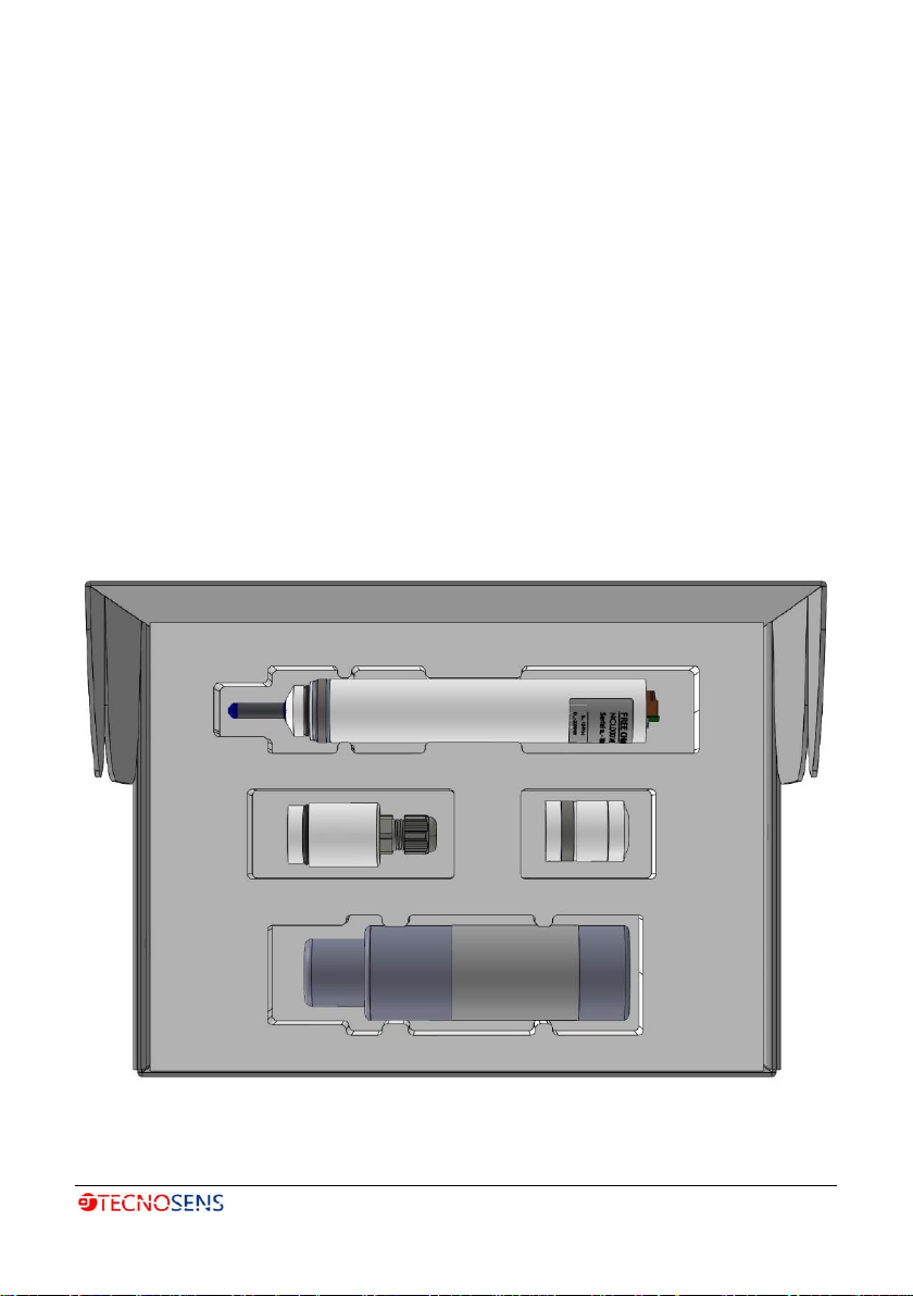
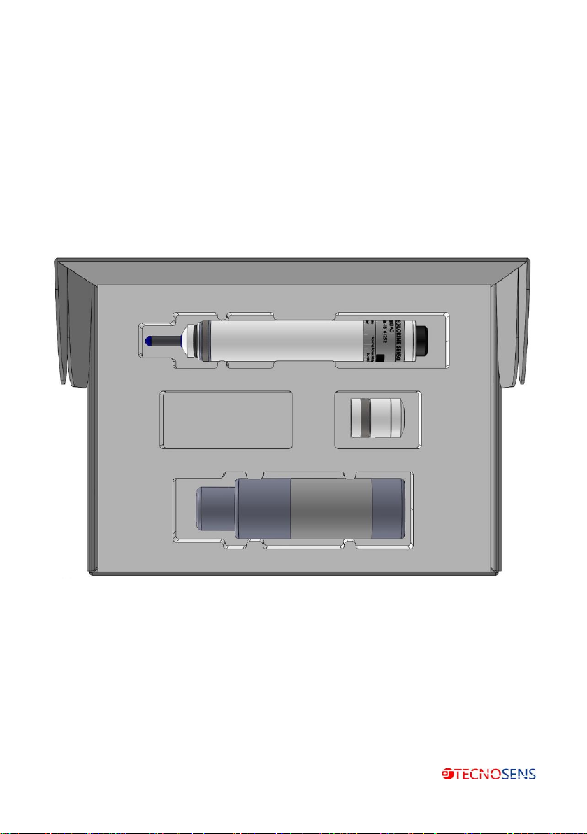
1.1 MATERIALS CONTAINED IN THE SET
The device is supplied in its packaging and is presented as shown in Figure 1 and
in Figure 2, in which the standard kit consists of:
I. sensor;
II. upper element (not present in
the version with voltage output);
III. membrane cap;
IV. bottle of gel electrolyte (100ml);
V. paper for polishing the gold
electrode;
VI. user manual
Figure 1: version with current output standard supply
1. Introduction
4
Figure 2: version with voltage output standard supply
1. Introduction
5
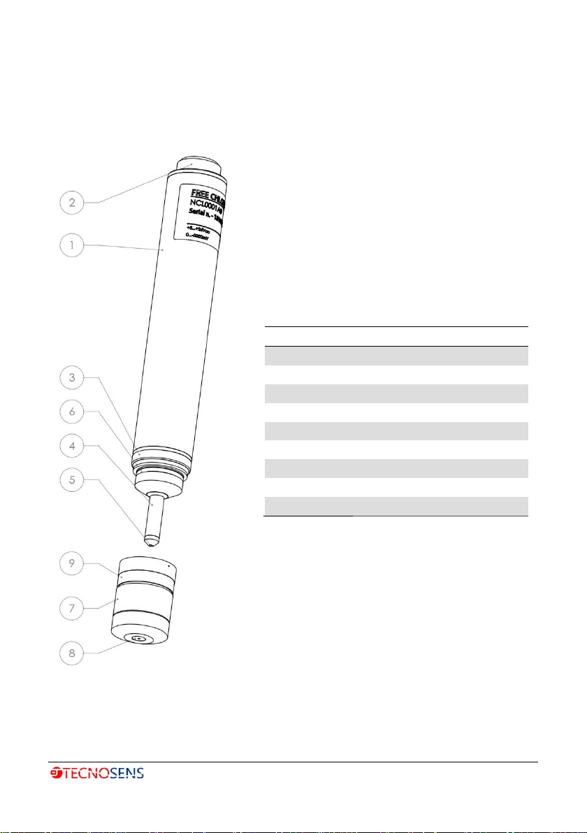
1.2 STRUCTURE OF THE SENSOR
The parts composing the sensor are shown in Figure 3.
Position
Description
1
Sensor body
2
Connector
3
Counter electrode
4
Reference Electrode
5
Working electrode
6
O-Ring
7
Cap
8
Membrane
9
Tubular gasket
Figure 3: Sensor structure and description of its components.

2. Installation
6
2INSTALLATION
2.1 ASSEMBLY/DISASSEMBLY OF THE CAP
Before proceeding with the assembly/disassembly operation of the cap from
the probe body, the tubular gasket must be moved from its position on the cap.
Pay attention that the vent hole, highlighted in Figure 4 and the other holes
present, remain uncovered throughout the assembly phase.
WARNING!
By leaving the tubular gasket in its place, during the operations of disassembly
and assembly of the cap from the probe, you risk damaging the membrane,
compromising the functioning of the probe. Also be careful not to cover the
upper holes with your fingers during the assembly or disassembly phase.
2.2 FILLING THE CAP WITH ELECTROLYTIC SOLUTION
Fill the cap with the gel electrolyte solution contained in the bottle present in
the package. The gel electrolyte must reach the edge of the cap, as reported in
Figure 4, leaving the tubular gasket displaced from its place.
Insert the probe vertically into the cap as shown in Figure 5 on the next page,
taking care during the assembly phase not to cover the excess gel outlet holes
with your fingers. This is in order not to damage the membrane and to avoid
the formation of air bubbles in the solution once the cap is tightened. By almost
completely screwing the cap to the probe, you will feel a slight resistance due
to the presence of the O-ring which guarantees the seal of the coupling.
Once the cap has reached the mechanic stop with the probe and the excess gel
has been expelled from the holes, the tubular gasket must be repositioned in
its place in order to avoid gel leaks during the normal use of the probe in flow.

2. Installation
7
Figure 4: Cap filling phase with gel electrolyte.
Figure 5: Assembly phase of the cap
on the probe.
SLOWLY SCREW THE PROBE CAP.
To ensure the correct functioning of the probe, it is necessary to avoid that
the air bubbles remain trapped inside the gel solution in the cap. For this
reason, it is useful to slowly screw the cap to the probe, and not to shake the
bottle before use.
After filling or restoring the electrolyte solution, the probe takes about an hour
to resume normal operation.
RESTORING THE ELECTROLYTIC SOLUTION
It is recommended to calibrate the instrument to which the probe is
connected after the operation has been restored. It is recommended to repeat
the calibration procedure after 24 h.

2. Installation
8
DO NOT TOUCH THE CAP AND ELECTRODES
Do not touch the membrane on the cap, nor the electrodes placed in the
lower part of the sensor; do not damage them and avoid that they come
into contact with greasy substances. Otherwise, the sensor will no longer
function accurately. In this case, replace the cap with a new one or send
the sensor to the manufacturer for cleaning the electrodes.
WARNING!
During all assembly, maintenance or other operations it is recommended not
to touch the membrane, in order to avoid damage that could lead to
malfunction of the probe.
2.3 INFORMATION ON THE ELECTROLYTE GEL
KEEP THE PRODUCT OUT OF REACH OF CHILDREN!
ELECTROLYTE GEL.
DO NOT SHAKE THE BOTTLE BEFORE USE!
✓The electrolyte is sensitive to oxidation: always keep the bottle of
electrolyte closed after use.
✓Do not transfer the electrolyte into other containers.
✓The electrolyte must not be stored beyond the permitted terms; for
the expiry date see the label on the electrolyte bottle.
✓Pour in the electrolyte avoiding, where possible, the formation of
bubbles. The small air bubbles are not a problem, while the larger
bubbles rise towards the upper edge of the cap and affect the
measurement.
✓Store the gel electrolyte bottle with the cap facing down, as indicated
on the bottle label.
2. Installation
9
WARNING!RISK DUE TO A DANGEROUS SUBSTANCE.
When using hazardous substances, please note that updated safety data
sheets of the manufacturers of these substances are available. Since the risk
potential of a substance can be re-evaluated at any time based on new
knowledge, the safety data sheet must be checked regularly and replaced if
necessary.
The system operator is responsible for the availability of the updated version
of the safety data sheet and for the preparation of the risk
assessment of the workplaces concerned connected to it.
The information relating to the gel electrolyte and the safety
data sheet are available on the manufacturer's website at
http://www.aedes.info/prodotto.asp
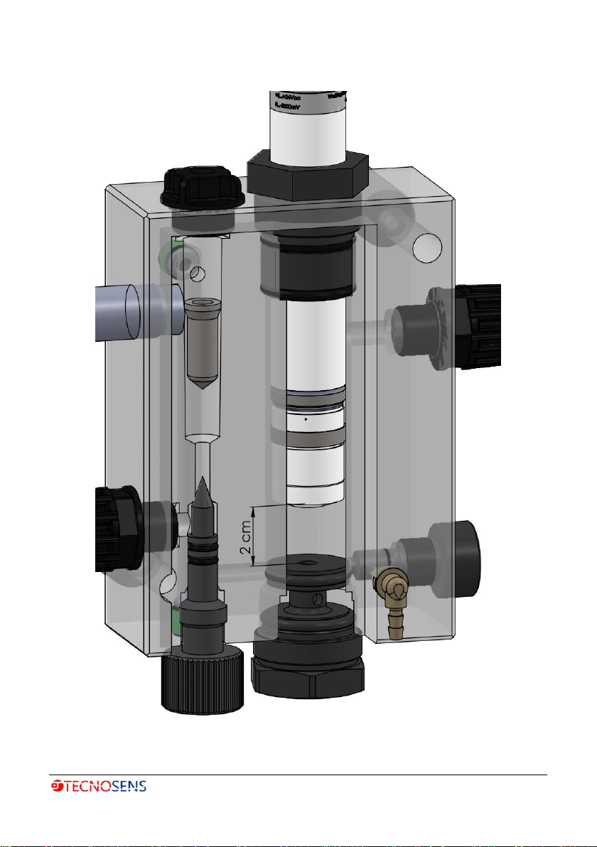
2.4 MOUNTING ON THE PROBE HOLDER
Insert the probe into a dedicated probe holder in the appropriate housing. A
distance of about 2 cm must be ensured between the membrane and the
bottom of the probe holder as indicated in Figure 6 on the next page, in order
to ensure optimal operation of the probe.
The phase of installing the probe in the probe holder must be carried out
delicately; do not push too hard to avoid the risk of damaging the membrane
due to excessive pressure. In order to avoid the occurrence of an overpressure
it is recommended to open at least one drain valve or sampling cock. Once the
probe is blocked in the probe holder at the desired height, it is possible to close
the drain valve or sampling cock, and gradually open the delivery cock.
2. Installation
10
INSTALLATION INSTRUCTION
✓
Make sure that the membrane does not come into contact with
other objects to avoid damage and obstruction of the membrane.
✓
Once the probe has been positioned on the probe holder, it is
recommended to slowly open the delivery cock to protect the
membrane from the pressure front produced by the water flow.
✓
After installation, the sensor must always be kept wet, e.g. the
probe holder must never run dry.
2.5 FLOW ADJUSTMENT
To ensure correct operation of the probe, the flow rate of fluid passing through
the probe holder must be between 30 l/h and 60 l/h and with a pressure
between 0 bar and 1 bar (the recommended working range for probe is 0.3 -
0.5 bar).
WATER FLOW
Do not exceed the recommended working range:
✓do not use the sensor with a lower or higher range than the indicated
limits;
✓before commissioning the probe, the flow rate must be measured
using suitable measurement methods.
INSTALLATION INSTRUCTIONS
Avoid installations that create air bubbles in the sample water. The air bubbles
adhering to the sensor membrane can cause an insufficient measurement
value. An insufficient measured value can lead to incorrect dosing in a control
circuit.
2. Installation
11
Figure 6: installation of the probe in a probe holder, where the optimal
operating distance is shown

3. Electrical Connections
12
3ELECTRICAL CONNECTIONS
3.1 ELECTRICAL INSTALLATION OF VOLTAGE OUTPUT
The probe equipped with the electric voltage output (0 ÷ −2000 mV) is provided
with a circular connector. It is essential, to connect the probe to the measuring
instrument, to use the dedicated electric cable (see paragraph 5.1 page 21 to
identify the code) to be purchased separately. The cable is made up on one side
of the connector and on the other of the wires as in Figure 7, to be connected
as shown in Table 2. For the electrical installation of the probe, it is necessary
to connect the cable to the measuring instrument and then couple the
connector on the cable to the connector on the probe.

3. Electrical Connections
13
Figure 7: Electrical connection of cables to the measuring instrument
Table 2: Characteristics of electrical connections
Terminal
Color
Function
Value
1
Green
Signal (Vout)
0 ÷ -2000 mVdc
2
Yellow
Signal (GND)
0
3
Brown
Power supply (+Vin)
+10 ÷ +30 Vdc
4
White
Power supply (GND)
0
Single Power Supply
Terminal
Color
Function
Value
1
Green
Signal (Vout)
0 ÷ -2000 mVdc
2
Yellow
Signal (GND)
0
3
Brown
Power supply (+Vin)
+5 ÷ +15 Vdc
4
White
Power supply (-Vin)
-5 ÷ -15 Vdc
Single Power Supply

3. Electrical Connections
14
3.2 ELECTRICAL INSTALLATION OF CURRENT OUTPUT
Below is reported the procedure for the electrical installation of the probes
equipped with the current output with two-wire connection, as shown in Figure
8
1. Rotate the upper element (3) of the sensor counterclockwise and
extract the upper element.
2. Loosen the locking nut (2) of the threaded connector and pass the
measuring cable (1) through it.
3. Uncover the ends of the cable by 0.5 cm, apply the cable lugs (ϕmax
=0.5 mm2) and connect them to the 2-conductor connection
respecting the polarity indicated on the terminal (4).
4. Fully insert the upper element of the sensor (3) on the probe body (5)
and tighten it by turning clockwise until it stops.
5. Insert the measurement cable as far as possible into the upper element
of the strain relief sensor.
6. Tighten the lock nut (2) on the threaded connector.
Terminal
Function
Value
+
Power supply (+Vin)
+12 ÷ 30 Vdc
-
Power supply (GND)
0

4. Activation and Maintenance of the Sensor
15
Figure 8: Electrical installation for probes with two-wire current output

4. Activation and Maintenance of the Sensor
16
4ACTIVATION AND MAINTENANCE OF THE SENSOR
4.1 SENSOR COMMISSIONING
Once the sensor has been mounted on the probe holder and checked the
correct working conditions, such as the probe insertion height, the control
water flow rate and the pressure, and the connection to the electrical
measuring system has been made, the activation times of the probe are those
shown in Table 3. In any case, the activation times depend on the working
conditions of the system where the sensor is placed.
Table 3: Activation times required for the probe to provide a stable signal
Phase
Time [h]
First Installation
1 ÷ 24
Subsequent installations
1 ÷ 24
Gel and/or Cap replacement
1 ÷ 3
4.2 CALIBRATION
The probe calibration must be carried out once the probe signal is stable,
therefore not before the activation times indicated in Table 3.
The calibration of the measuring instrument connected to the probe must be
carried out and checked periodically using the DPD-1 method ("Free Chlorine").
PROBE CALIBRATION
Depending on the accuracy required of the probe, it may be necessary to
calibrate once a week. It may be necessary to carry out calibration whenever
the working conditions of the water are changed (analyte concentration,
temperature or pressure), or after replacing the gel electrolyte and/or
membrane.
This manual suits for next models
25
Table of contents


