Vimar Elvox EFA3 User manual

Manuale per il collegamento e l’uso
Connection and operating manual
EFA3
Fotocellula da esterno parete
External wall photocell

2
12-24 Vac/dc
12/24 Vac
COLLEGAMENTO DI 1 COPPIA DI FOTOCELLULE
CONNECTION OF A PAIR OF PHOTOELECTRIC CELLS
RX2 TX1
NO COM
-
+
-
+
(NC)
FSW
RX1 RX2
+
COM
NC
-
TX1 TX2
NO COM
-
+
NO COM
-
+
-
+
-
+
RX2 TX1
NO COM
-
+
-
+
+
COM
NC
-
N0
RX1 RX2
COM
NC
TX1 TX2
NO COM
(NC)
-
+
NO COM
(NC)
-
+
-
+
-
+
~
~
PSW PSW
(NC)
FSW
(NC)
FSW
(NC)
FSW
Fig. 1
Fig. 2
Fig. 3
Fig. 4
LED RX LED TX
RICEVITORE
RECEICER
TRASMETTITORE
TRANSMITTER
{
{
RX1 RX2
+
COM
NC
-
TX1 TX2
NO COM
-
+
NO COM
-
+
-
+
-
+
RX2 TX1
NO COM
-
+
-
+
+
COM
NC
-
N0
RX1 RX2
COM
NC
TX1 TX2
NO COM
(NC)
-
+
NO COM
(NC)
-
+
-
+
-
+
~
~
PSW PSW
(NC)
FSW
(NC)
FSW
(NC)
FSW
EN
I
COLLEGAMENTO DI DUE COPPIE DI FOTOCELLULE SINCRONIZZATE (SOLO ALIMENTAZIONE ALTERNATA)
CONNECTION OF TWO PAIRS OF SYNCHRONISED PHOTOCELLS (ALTERNATE POWER ONLY)

3
FOTOCELLULE EFA3
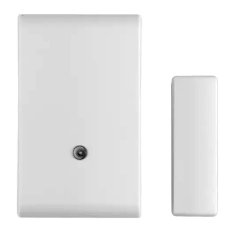
Fotocellula sincronizzata da esterno a parete.
Costituita da ricevitore (RX) e da un trasmettitore (TX) a raggi infrarossi modulati.
N.B. È vietato l’uso per riessione a l’installazione in superci non rigide soggette a vibrazioni.
CARATTERISTICHE TECNICHE:
- Alimentazione:
12-24Vac
12 – 28Vdc
- Assorbimento max.:
a 12 V: Rx 34 mA, Tx (min) 13 mA
a 24 V: Rx 53 mA, Tx (min) 15 mA
- Portata relè: 1 A a 24 V d.c. / 120 V a.c.
- Tempo di risposta: < 30 ms.
- Temperatura di funzionamento: -20° C ¸ +55° C
- Grado di protezione: IP55
- Portata massima: 15 m
N.B La portata si può ridurre del 50% in presenza di fenomeni atmosferici: nebbia, pioggia, polvere ecc.
Dimensioni (LxHxP): 58x87x44 mm
INSTALLAZIONE:
1) Inserire un cacciavite a taglio nella fessura ricavata nel lato inferiore del coperchio (vedi Fig. 1).
2) Fissare il fondo della fotocellula in parete, applicando 2 tasselli per il ssaggio a muro o 2 viti autolettanti con diametro 3,9
mm per il ssaggio su ferro, cercando di ottenere l’allineamento migliore.
COLLEGAMENTI
1) Eseguire il collegamento elettrico prestando attenzione nel rispettare la polarità sul ricevitore e il trasmettitore, se alimentate
in corrente continua.
2) Nel caso di due trasmettitori (TX) vicini, il raggio di uno potrebbe interferire sull’altro ricevitore non garantendo il corretto
funzionamento.
Per ovviare questo problema, se disponibile l’alimentazione in corrente alternata, è possibile utilizzare il sistema di sincronismo
che permette di far funzionare alternativamente le due coppie di fotocellule.
Per attivare la funzione di sincronismo è necessario rispettare il collegamento riportato in gura 4.
LED Signicato
LED TX di colore blu ,segnala la presenza di alimentazione nel trasmettitore della fotocellula, nel caso non sia acceso control-
lare la polarità dell’alimentazione. Il LED RX di colore blu, segnala il corretto allineamento del TX e del RX della fotocellula, si
spegne occupando la fotocellula
4) Eseguita l’installazione della fotocellula. Controllare il funzionamento interrompendo più volte il fascio (raggio infrarosso);
vericare il spegnimento del LED RX e la commutazione del relè.
5) Eseguito il collaudo posizionare il frontalino.
I

4
AVVERTENZE PER L’INSTALLATORE
- Leggere attentamente le avvertenze contenute nel presente documento in quanto forniscono importanti indicazioni riguardanti
la sicurezza di installazione, d’uso e di manutenzione.
- Dopo aver tolto l’imballaggio assicurarsi dell’integrità del l’ap pa rec chio. Gli ele men ti dell’imballaggio (sacchetti di pla sti ca, po-
li sti ro lo espanso, ecc.) non devono essere lasciati alla portata dei bambini in quanto potenziali fonti di pericolo. L’esecuzione
dell’impianto deve essere rispondente alle norme CEI vigenti.
- Prima di col le ga re l’apparecchio ac cer tar si che i dati di targa siano rispondenti a quelli della rete di di stri bu zio ne.
- Questo apparecchio dovrà essere destinato solo all’uso per il quale è stato espressamente concepito, e cioè per i sistemi di
automazione per cancelli, porte da garage e barriere stradali. Ogni altro uso è da con si de rar si im pro prio e quindi pericoloso.
Il costruttore non può essere con si de ra to re spon sa bi le per even tua li danni derivanti da usi impropri, erronei ed ir ra gio ne vo li.
- Prima di effettuare qualsiasi operazione di pulizia o di manutenzione, disinserire l’apparecchio dalla rete di alimentazione
elettrica, spegnendo l’interruttore dell’impianto.
- In caso di guasto e/o di cattivo funzionamento dell’apparecchio, togliere l’alimentazione mediante l’interruttore e non ma-
nomettere l’apparecchio. Per l’eventuale riparazione rivolgersi solamente ad un centro di assistenza tecnica autorizzato dal
costruttore. Il mancato rispetto di quanto sopra può compromettere la sicurezza dell’apparecchio.
- L’installatore deve assicurarsi che le informazioni per l’utente siano presenti sugli apparecchi derivati.
- Tutti gli apparecchi costituenti l’impianto devono essere destinati esclusivamente all’uso per cui sono stati concepiti.
- ATTENZIONE: per evitare di ferirsi, questo apparecchio deve essere assicurato alla parete secondo le istruzioni di installa-
zione.
- Questo documento dovrà sempre rimanere allegato alla documentazione dell’impianto.
Direttiva 2002/96/CE (WEEE, RAEE).
Il simbolo del cestino barrato riportato sull’apparecchio indica che il prodotto, alla ne della propria vita utile, dovendo essere
trattato separatamente dai riuti domestici, deve essere conferito in un centro di raccolta differenziata per apparecchiature elet-
triche ed elettroniche oppure riconsegnato al rivenditore al momento dell’acquisto di una nuova apparecchiatura equivalente.
L’utente è responsabile del conferimento dell’apparecchio a ne vita alle appropriate strutture di raccolta. L’adeguata
raccolta differenziata per l’avvio successivo dell’apparecchio dismesso al riciclaggio, al trattamento e allo smaltimento
ambientalmente compatibile contribuisce ad evitare possibili effetti negativi sull’ambiente e sulla salute e favorisce il riciclo
dei materiali di cui è composto il prodotto. Per informazioni più dettagliate inerenti i sistemi di raccolta disponibili, rivolgersi
al servizio locale di smaltimento riuti, o al negozio in cui è stato effettuato l’acquisto.
Rischi legati alle sostanze considerate pericolose (WEEE).
Secondo la nuova Direttiva WEEE sostanze che da tempo sono utilizzate comunemente su apparecchi elettrici ed elettronici sono
considerate sostanze pericolose per le persone e l’ambiente. L’adeguata raccolta differenziata per l’avvio successivo dell’appa-
recchio dismesso al riciclaggio, al trattamento e allo smaltimento ambientalmente compatibile contribuisce ad evitare possibili
effetti negativi sull’ambiente e sulla salute e favorisce il riciclo dei materiali di cui è composto il prodotto.
Il prodotto è conforme alla direttiva europea 2004/108/CE e successive.
I
5
EN
EFA3 PHOTOCELLS
External wall synchronised photocell.
Consisting of receiver (RX) and transmitter (TX) with modulated infrared rays.
N.B. Use for backscattering the installation on non-rigid surfaces subject to vibrations is forbidden.
TECHNICAL CHARACTERISTICS:
- Supply voltage:
12-24Vac
12 – 28Vdc
- Max. absorption:
at 12 V: Rx 34 mA, Tx (min) 13 mA
at 24 V: Rx 53 mA, Tx (min) 15 mA
- Relay power: 1 A at 24 V d.c. / 120 V a.c.
- Answer time: < 30 ms.
- Operating temperature: -20° C ¸ +55° C
- Protection rating: IP55
- Max. range: 15 m
N.B The range may decrease by 50% when there are atmospheric phenomena: fog, rain, dust etc.
Dimensions (WxHxD): 58x87x44 mm
INSTALLATION:
1) Insert a at screwdriver in the groove in the lower side of the cover (see Fig. 1).
2) Fix the bottom of the photocell to the wall, using 2 wall xing plugs or 2 self-threading screws with diameter 3.9 mm for metal
xing, aiming to obtain the best possible alignment.
CONNECTIONS
1) Make the electrical connection taking care to respect the polarity of the receiver and transmitter, when powered by contin-
uous current.
2) With two transmitters (TX) nearby, the ray of one could interfere with the other receiver, compromising correct operation.
To avoid this problem, if alternating current is available, it is possible to use the synchronism system which allows two pairs of
photocells to work alternately.
To enable the synchronism function, make the connections as shown in gure 4.
LED Meanings
LED TX, blue,signals the presence of power in the photocell transmitter, if not lit check the power polarity. The blue LED RX
signals the correct alignment of the photocell TX and RX, and goes out when the photocell is occupied
4) Having installed the photocell. Check the operations by breaking the beam (infra-red beam) several times; check that the
LED RX goes out and that the relay commutates.
5) Having completed the test, replace the front panel.

6
SAFETY INSTRUCTIONS FOR INSTALLERS
- Carefully read the instructions on this leaet: they give important information on the safety, use and maintenance of the instal-
lation.
- After removing the packing, check the integrity of the set. Packing components (plastic bags, expanded polystyrene etc.) are
dangerous for children. Installation must be carried out according to national safety regulations.
- Before connecting the set, ensure that the data on the label correspond to those of the mains.
- This apparatus must only be used for the purpose for which it was expressly designed, e.g. for automation systems for gates,
garage doors and road barriers. Any other use may be dangerous. The manufacturer is not responsible for damage caused
by improper, erroneous or irrational use.
- Before cleaning or maintenance, disconnect the set.
- In the event of faults and/or malfunctions, disconnect from the power supply immediately by means of the switch and do not
tamper with the apparatus.
- For repairs apply only to the technical assistance centre authorized by the manufacturer.
- Safety may be compromised if these instructions are disregarded.
- Installers must ensure that manuals with the above instructions are left on connected units after installation, for users’ infor-
mation.
- All items must only be used for the purposes designed.
- WARNING: to prevent injury, this apparatus must be securely attached to the wall in accordance with the installation instruc-
tions.
- This leaet must always be enclosed with the equipment.
Directive 2002/96/EC (WEEE)
The crossed-out wheelie bin symbol marked on the product indicates that at the end of its useful life, the product must be
handled separately from household refuse and must therefore be assigned to a differentiated collection centre for electrical
and electronic equipment or returned to the dealer upon purchase of a new, equivalent item of equipment.
The user is responsible for assigning the equipment, at the end of its life, to the appropriate collection facilities.
Suitable differentiated collection, for the purpose of subsequent recycling of decommissioned equipment and environmentally
compatible treatment and disposal, helps prevent potential negative effects on health and the environment and promotes the
recycling of the materials of which the product is made. For further details regarding the collection systems available, contact
your local waste disposal service or the shop from which the equipment was purchased.
Risks connected to substances considered as dangerous (WEEE).
According to the WEEE Directive, substances since long usually used on electric and electronic appliances are considered
dangerous for people and the environment. The adequate differentiated collection for the subsequent dispatch of the appliance
for the recycling, treatment and dismantling (compatible with the environment) help to avoid possible negative effects on the
environment and health and promote the recycling of material with which the product is compound.
Product is according to EC Directive 2004/108/CE, 2006/95/CE and following norms.
EN

7

Vimar SpA: Viale Vicenza, 14
36063 Marostica VI - Italy
Tel. +39 0424 488 600 - Fax (Italia) 0424 488 188
Fax (Export) 0424 488 709
www.vimar.com
S6I.EFA.300 03 15 03
VIMAR - Marostica - Italy
Table of contents
Languages:
Other Vimar Accessories manuals

Vimar
Vimar Elvox EDP1 User manual

Vimar
Vimar Elvox K40960 User manual

Vimar
Vimar Eikon 20784 User manual

Vimar
Vimar Arke 19784 User manual

Vimar
Vimar Eikon 20281 User manual

Vimar
Vimar Eikon Evo 21296 User manual

Vimar
Vimar ELVOX 6931 Assembly instructions

Vimar
Vimar Elvox K40960 User manual

Vimar
Vimar Eikon User manual

Vimar
Vimar 02692 User manual
Popular Accessories manuals by other brands

Comfort Sync
Comfort Sync 1.851400 Installation and Homeowners Guide

BD Sensors
BD Sensors DM 10 Mounting instructions

Costway
Costway OP70367 user manual

Dometic
Dometic CoolFreeze operating manual

Image Sensing Systems
Image Sensing Systems RTMS G4 user manual

Arizona Air Coolers
Arizona Air Coolers Kool Kube AZ100MA owner's manual