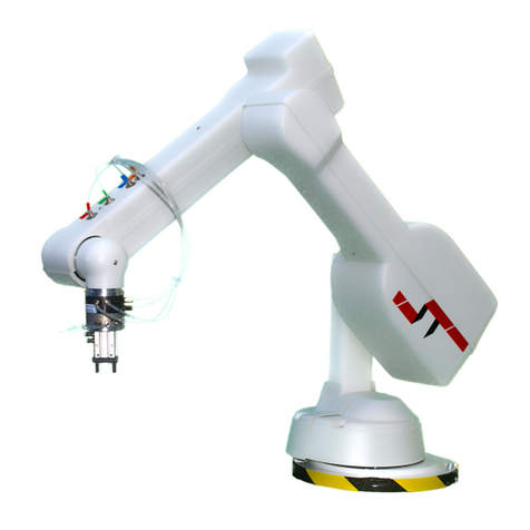
Tecnospiro ROSCAMAT-500 Series User manual

OPERATOR’S
MANUAL
Range
ROSCAMAT-500
Serial no. Machine no.
Model
Year of
manufacture
Polígono Industrial Pla dels Vinyats, B – 08250 Sant Joan de Vilatorrada(Barcelona) Spain
+34 93 876.42.42 / +34 93 876.43.59 +34 93 876.77.38 / +34 93 876.40.44
E-mail :[email protected] – http://www.tecnospiromt.com

2
CONTENTS
Pagenr
Introduction
................................... 3
Description R-500 RH ....................... 4
Working areas R-500 RH .......... 5
Description R-500 ............................ 6
Working areas R-500
................ 7
Description R-500 (C-26 N) ................. 8
Working areas R-500 (C-26 N)....... 9
Description
.................................... 10
Installation
..................................... 12
Verification
............................ 13
Operation ......................................... 14
Anomalies
............................... 15
Technical data
................................. 16
Maintenance
................................ 18
Repairs
........................... 19
Operation R-500 RH .............................. 24
Spare parts list ............................ 27
Standard products range .................... 37

3
INTRODUCTION
Dear customer:
We wish to take this opportunity to thank you for choosing a
“ROSCAMAT” tapping machine to produce quality threads ans associated
operations.
This operation’s manual is given to you so that by careful reading of its
contents, it will be enable you to maintain its reliability and performance
for long-life.

4
DESCRIPTION MACHINE ROSCAMAT-500 RH
1. MOTOR
2. FRONT BELLOW
3. TILTING ARMS
4. REAR BELLOW
5. ARM LOCKING KNOB
6. RADIAL ARM
7. AIR INLET SPIGOT
8. MACHINE BASE PLATE
9. BRAKE HANDLE
10. AIR & LUB PREPARATION UNIT
11. REAR DAMPER REGULATING
HANDWHEEL
12. CAPS
13. UPPER HAT
14. FRONT DAMPER REGULATING
HANDWHEEL
15. AIR PIPE
16. ARM LOCKING CONTROL
17. HEAD LOCKING HANDLE
18. MULTIPOSITION HEAD
19. TAPHOLDER
20. MODULE
The basic machine consists of a
radial parallelogram, plus two pendular
parallelograms which are balanced by
pneumatic springs and a two-rotation
axis head. This group fixes the motor
and keeps it perpendicular to the
working area.
El motor is equipped with a module
quick-change system, and rotates by
compressed air, that has previously
been filtered and lubricated by a unit
for that purpose.
Taps and shank tooling fit directly
to quick-change tapholders.

5
WORKING AREAS ROSCAMAT-500 RH

6
DESCRIPTION MACHINE ROSCAMAT-500
1. MOTOR
2. AIR PIPE
3. UPPER HAT
4. FRONT DAMPER REGULATION
HANDWHEEL
5. CAPS
6. REAR DAMPER REGULATION
HANDWHEEL
7. REAR BELLOW
8. AIR GROUP
9. AIR INLET SPIGOT
10. MACHINE BASE PLATE
11. RADIAL ARM
12. BRAKE HANDLE
13. TILTING ARMS
14. FRONT BELLOW
15. VERTICAL HEAD
16. TAPHOLDER
17. MODULE
The basic machine consists of a radial
arm, plus two pendular parallelograms
which are balanced by pneumatic
springs. This group fixes the motor head
and keeps it perpendicular to the
working area.
The motor is equipped with a module
quick-change system and rotates by
compressed air that has previously been
filtered and lubricated by a unit for that
purpose.
Tools and shank tooling fit directly
to the quick-change tapholders.

7
WORKING AREAS ROSCAMAT-500

8
DESCRIPCTION MACHINE ROSCAMAT-500 (C-26 N)
The ROSCAMAT-500 can be supplied with an articulated head (C-26
N). This bracket of easy handling can be set in four different positions 90º
apart.
Orientable head:
1.- Handle
2.- Milled nut
Vertical operations:
Place the motor in vertical position and lock the handle (1) and the milled
nut (2). The ROSCAMAT now is ready to work.
Horizontal operations:
Loose the milled nut (2) to unlock the joint of the motor.
Turn the head 90º till you reach the interlock, and then tighten the millet
nut (2) again.
Unlock the handle (1) located in the upper side of the head.
When moving the arm, the operator will have to manually maintain the
perpendicularity to the working plane.
Do not lock the handle (1) if you are working in horizontal operations.

9
WORKING AREAS ROSCAMAT-500 (C-26 N)

10
DESCRIPTION
PNEUMATIC MOTOR TS-VIII
REGULATING FILTER UNIT AIR LUBRICATION
1b.- Pressure regulator
2b.- Flow rate regulating valve
3b.- Pressure gauge
4b.- Reservoir (condensed water)
5b.- Drain pipe (WATER)
6b.- Oil reservoir (SAE-10)
7b.- Lubrication regulation knob
8b.- Lubrication inspection sight glass
1.- Starting lever
2.- Reversing button
3.- Motor Head
4.- Module change slide collar
5.- Module
6.- Quick change (module)
7.- Tapholder with clutch

11
DESCRIPTION
AUTOMATIC TAP LUBRICATOR EQUIPMENT (E)
The machines of the model ROSCAMAT 500 E / 500 (C26 N) E /500 RH E,
incorporate an automatic tap lubrication system.
The oil reservoir is arranged inside the radial arm and is connected to an
innerly arranged hydraulic cylinder. The desired cutting oil flow rate is
adjusted by means of ten control valve (3). When pressing the motor lever the
system pumps the flow rate in the pump being arranged the tilting arm.
After having filled the oil reservoir, immediately bleed the system by applying
pressurised air through the hole being provided in the filling cap (1) of the
reservoir.
*Caution: USE CUTTING OIL
Certain lubricant types containing trichlorines and alcohols can damage some
of the valve components.
1.- Filling cap
2.- Drain screw
3.- Regulation valve
4.- Articulated pipe

12
INSTALLATION
A : Mount the machine base plate on to the working table by means
of three M8 screws or the clamp.
B : Fill up the reservoir (6b, page 10) with lubricating oil SAE-10.
C : The air connection is carried out by means of a notched
connections (17, page 4 y 14, page 6 ) located on the machine
base.
IMPORTANT:
Table showing the ratio length to inside diameter of the feeding pipe:
Length (mts.) Minimum inside diameter. (mm.)
< 8 12
> 8 14

13
INSTALLATION VERIFICATION
Once the machine has been connected to the main, have to be checked:
1. Supply pressure:
6-8 bar for full power
2. The pressure gauge reading can drop 0,5 maximum 1,5 bar when the
motor is started (if a drop greater than 2 bar is noticed, this means that
the supply flow rate is not sufficient).
3. Make sure, by checking the sight glass (8b, page 10) that when the
machine is in operation two to three drops per minute are fed. The
regulation is carried out by means of the control knob. (7b, page 10).
4. Arm balance:
By turning the regulation handwheel (11 and 14, page.4) and (4 and 6,
page.6) to the right (-) or to the left (+) different weight at the arm end
are balanced.

14
OPERATION
1. Turn the slide collar (4, page 10) to the left, insert the module and turn
the slide collar to the right.
2. Regulate the arm balance for the 90 and 170 modules.
3. Insert the tapholder in the quick change of the module.
4. Clockwise rotation: push lever (1, page 10)
5. Counterclockwise rotation: push simultaneously lever (1, page 10) and
button (2, page 10).
6. Pulling up the tool quick change (6, page 10) the tapholder will come
out automatically.
SPEED CONTROL - CONSUMPTION CONTROL
By means of the flowrate regulating valves (2b, page 10) and the pressure
regulator (1b, page 10).
RATIO VALVE POSITION
(Consumption-Pressure-Rotation speed)
Module Maximum
Speed
(rpm)
Maximum
Torque
(Nm)
Coupling
diameter
(mm.)
Max. Thread.
Aluminium
Cast Iron
Max. Thread
Steel < 80 Kg.. Max. Thread
Steel >80Kg.
90 90 150 31 M27 M24 M22
170 170 79 31 M22 M18 M16
300 300 44 19 M16 M16 M14
550 550 24 19 M14 M12 M10
750 750 17 19 M12 M10 M8
1.050 1.050 12,5 19 M8 M8 M6
2.100 2.100 6 Cone B-16
To drill up to 8 Aluminium, Brass, Cast Iron,..

15
OPERATION ANOMALIES
Slipping clutch type tapholders. The clutch slips and the tap cannot be
turned.
1. Clutch slackness. Clutch adjustment (page 15)
2. No tools lubrication. Use cutting oil.
3. Inappropriate tap for the material to machine. Use the correct tap. (page
16).
4. Tap spoiled “worn”.
5. Misaligned hole.
6. Drilled hole diameter too small.
When neither the tap or the motor turns, this could be attributed to one of
the previous items 2 to 6, or to insufficient motor power.
1. Check items 1 to 3 (page 13).
2. MINIMUM pressure 6 bar (for high power and rotation speed).
3. Clogged exhaust filter (page 19).
4. Worn motor plates (pages 20 y 21).
If the pivoted arm drops:
1. Arm not balanced. Check item 4 (page 13).
2. Faulty damper. Substitution (page 22, 23).
If the lubrication system don’t work:
1. The oil tank is empty. Fill the reservoir ( page 11)
2. The oil-hole is clogged. Introduce a un a 0,3-0,4 mm wire through the
oil-hole.
Upon having filled the oil reservoir immediately bleed the system
(page 11)
CLUTCH ADJUSTMENT
Remove small spring clip around perimeter and turn the notched nut
clockwise or counter clockwise to increase or decrease the clutch tension and
put the small ring back on the new notch.

16
TECHNICAL DATA
TURNING TORQUE (Nm) FOR THREADING
Metric thread Steel > 100 Kg. Steel 80-100 Kg. Steel < 80Kg. Aluminium
Cast Iron
2
3
4 2 1.3 1.2 0.8
5 3 2 2 1.3
6 5 4 4 2.4
8 11 8 8 5
10 20 15 14 9
12 33 24 23 14
14 50 36 35 22
16 57 42 40 26
18 101 73 70 45
20 112 81 78 50
22 123 90 86 55
24 194 140 135 86
27 218 158 152 97
MACHINE TAPS
Blind hole Helical-flute tap.
Lubrication
Through hole Straight-flute tap with helical
feed-in
Steel > 80 Kg. Rake angle 8-10. Cutting oil with additive.
Steel < 80 Kg. Rake angle 12-14.
Cutting oil.
Steel < 50 Kg. Stainless Rake angle 14-16.
Surface treatment.
Cast Iron Straight-flute tap. Surface
treatment. Nitrated.
Rake angle 5.
Petroleum, Coolant, dry
machining.
Duraluminium Rake angle 12-15. Coolant, dry machining
Aluminium
Rake angle 17-25. Cutting oil with additive.
Plastics Coolant, dry machining.

17
TECHNICAL DATA
R-500 RH R-500
Pneumatic motor:
Power 730 W. 730 W.
Consumption 300-900 l/m 300-900 l/m
Machine weight 39 Kg. 27 Kg.
Intake filter 5 U.m. 5 U.m.
Noise level 78 db. 78 db.
Machine colours Blue to RAL 5002
Fog grey to RAL 7035
(Pneumatic motor TS-VIII)

18
MAINTENANCE
Practically the only machine’s part that we can wear is the motor.
Therefore its maintenance should be carried out very carefully, which means
that the air supply must be in dry & clean condition. For this purpose, the
following three points must be taken into account:
1. Drain periodically the water collected in the left air treatment
unit cup by pressing the relief knob (5b, page 10).
2. Fill up the right air treatment unit cup with SAE-10 (light duty
oil).
3. Check through the sight glass (8b, page 10) that when the
machine is in operation, two or three drops per minute are
supplied. The regulation is made by means of the control knob
(7b, page 10).
WARRANTY
The warranty period for the motor and for the rest of the machine is one
year. The warranty does not cover any damage caused by overloads or
improper handling of the machine.

19
MAINTENANCE REPAIRS
EXHAUST FILTER (REPLACEMENT) Ref. 40202304
1. Close the flow rate regulating valve situated on
the left-hand side of the filtering unit (2b, page
10) and actuate the motor starting lever.
2. Take out the intake tube and the reversing
button (1, 4).
3. Unscrew the raccord (2) situated on the upper
side of the motor. Remove the external casing
(3) and take out the exhaust filter.
4. Replace the exhaust filter.
Reverse the process for the reassembling.
INTAKE FILTER (REPLACEMENT) Ref. NH120856
Remove the left air treatment unit cup (4b, page 10), unscrew the filter
and replace it with a new one. The installation is carried out in the reverse
order.
MOTOR REPLACEMENT Ref. 40201105
1. Close the air inlet valve (2b,page 10) being arranged to the left of the
FRL air servicing unit and actuate the motor air lever to expel the air
compressed.
2. Disconnect the air intake pipe being connected upper the motor
3. Remove the motor slide change collar (4, page 10). First, you must
remove the “seeger ring” situated under the lower part of the slide
collar.
WATCH THE Ø9 mm. BALLS OF THE INSIDE OF THE SLIDE CHANGE COLLAR
4. Loosen the two ALLEN screws of the head
5. To extract the motor (upwards), you must align the bolt ø2,5 mm of the
motor gearbox with the front milled gap of the machine motorhead
Carry out the whole process in reverse order for the assembly.

20
MAINTENANCE REPAIRS
PRESSURE GAUGE (REPLACEMENT) Ref. NH40516
1. Close the flow control valve (2b, page 10), and actuate the motor lever
in order to expel the compressed air from the inside of the motor
2. Turn the manometer "sight" to the right, and unscrew the two screws
securing the manometer to the FRL air servicing unit.
Replace the manometer with a new one, and carry out the whole process in
reverse order
MOTOR PLATES (REPLACEMENT) Ref. NH120846
1. Close the air inlet valve (2b, page 10) located on the left side of the
filtering unit and operate the motor to expel the air.
2. Remove the intake pipe entering the top of the motor.
3. With a “belt key”, unscrew (LEFT HAND THREAD) the motor casing.
4. Remove the whole rotor assembly from inside the casing.
5. Pull out the “seeger ring” (nr.6) of the upper part of the motor and
remove the upper head (nr. 4), the stator (nr.2) and the MOTOR
PLATES (nr.3).
ATTENTION:
Notice the direction and positions of the motor
stator and top head.
1. Rotor
2. Stator
3. Motor plates
4. Top head
5. Ball bearing 607-Z THB
6. “Seeger” O-ring
7. Bottom head
8. Ball bearing 6000-Z THB
9. Joint
10. Rod
This manual suits for next models
1
Table of contents
Other Tecnospiro Robotics manuals
Popular Robotics manuals by other brands
rozum robotics
rozum robotics Pulse Operator's manual

ROKAE
ROKAE xMate CR18 Hardware installation manual

Robokits
Robokits TrackBot RKI-1247 Assembly guide and user manual
killerspin
killerspin THUNDER Assembly and operating instructions

Omron
Omron Medium Series Hardware installation manual
Kinova
Kinova JACO Driver installation guide
