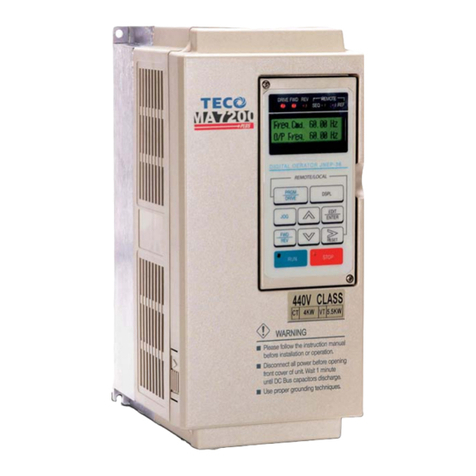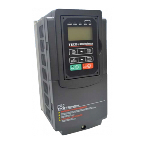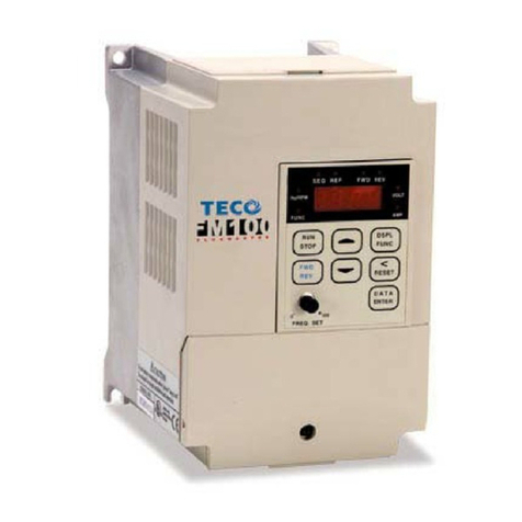
MA7200 PLUS Operating Manual
TECO – Westinghouse Motor Company Index
Table of Contents
Page
1.0 MA7200 PLUS Inspection, Handling and Installation..............................................
1.1.Inspection Procedure Upon Receiving...............................................................................
1.2 Installation.............................................................................................................................
1.3 Removing the Front Cover and Digital Operator...............................................................
2.0 General Wiring Diagrams...........................................................................................
3.0 Power Section, Terminal Layout, Wiring and Ratings...........................................
3.1 Power Terminals...................................................................................................................
3.2 Power Input / Output Block Diagrams................................................................................
3.3 Wiring Precautions...............................................................................................................
3.4 Power Input Wire Size, NFB and MCB Part Numbers........................................................
3.5 Notes for Circuit Protection and Environmental Ratings................................................
3.6 Electrical Ratings for Constant Torque and Quadratic Torque......................................
3.7 Inverter Heat Loss...............................................................................................................
4.0 Control Terminals Designations and Wiring...........................................................
4.1 Control Terminals Layout....................................................................................................
4.2 Control Circuit Wiring..........................................................................................................
5.0 Peripheral Power Devices Overview.........................................................................
5.1 AC Input Reactor..................................................................................................................
5.2 Input Fuse Types and Ratings............................................................................................
5.3 Noise Filters..........................................................................................................................
5.4 Braking Resistors and Braking Units................................................................................
6.0 Peripheral Control Devices.......................................................................................
6.1 LCD Operator with Extension Cable..................................................................................
6.2 Analog Operator...................................................................................................................
6.3 PROFIBUS Communication Card.......................................................................................
7.0 MA7200 PLUS Specifications....................................................................................
7.1 Basic Specifications............................................................................................................
7.2 General Specifications.........................................................................................................
7.3 MA7200 PLUS Dimensions and Weights...........................................................................
8.0 Parameter Groups, The Digital Operator, Menus and Keypad Navigation............
8.1 Parameter Groups................................................................................................................
8.2 Digital Operator Layout and Description...........................................................................
8.3 Digital Operator Key Functions...........................................................................................
8.4 Run / Stop Status Indicators...............................................................................................
8.5 Display Menu for DRIVE and PRGM Modes.......................................................................
8.6 Some Examples of keypad navigation...............................................................................
Cont.


