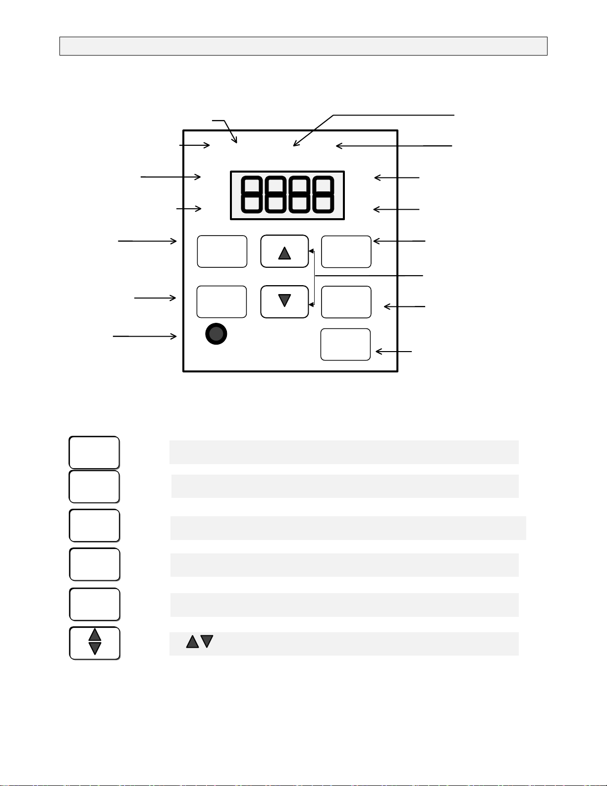
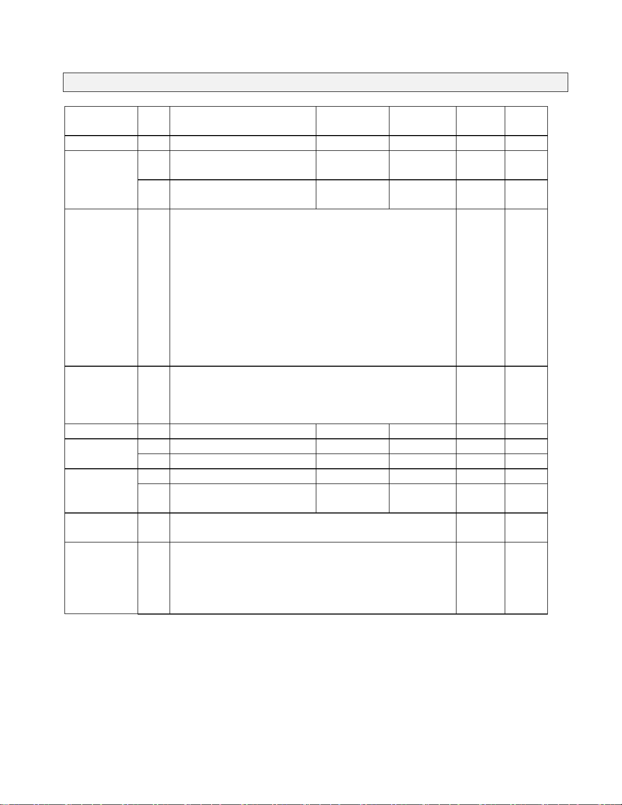
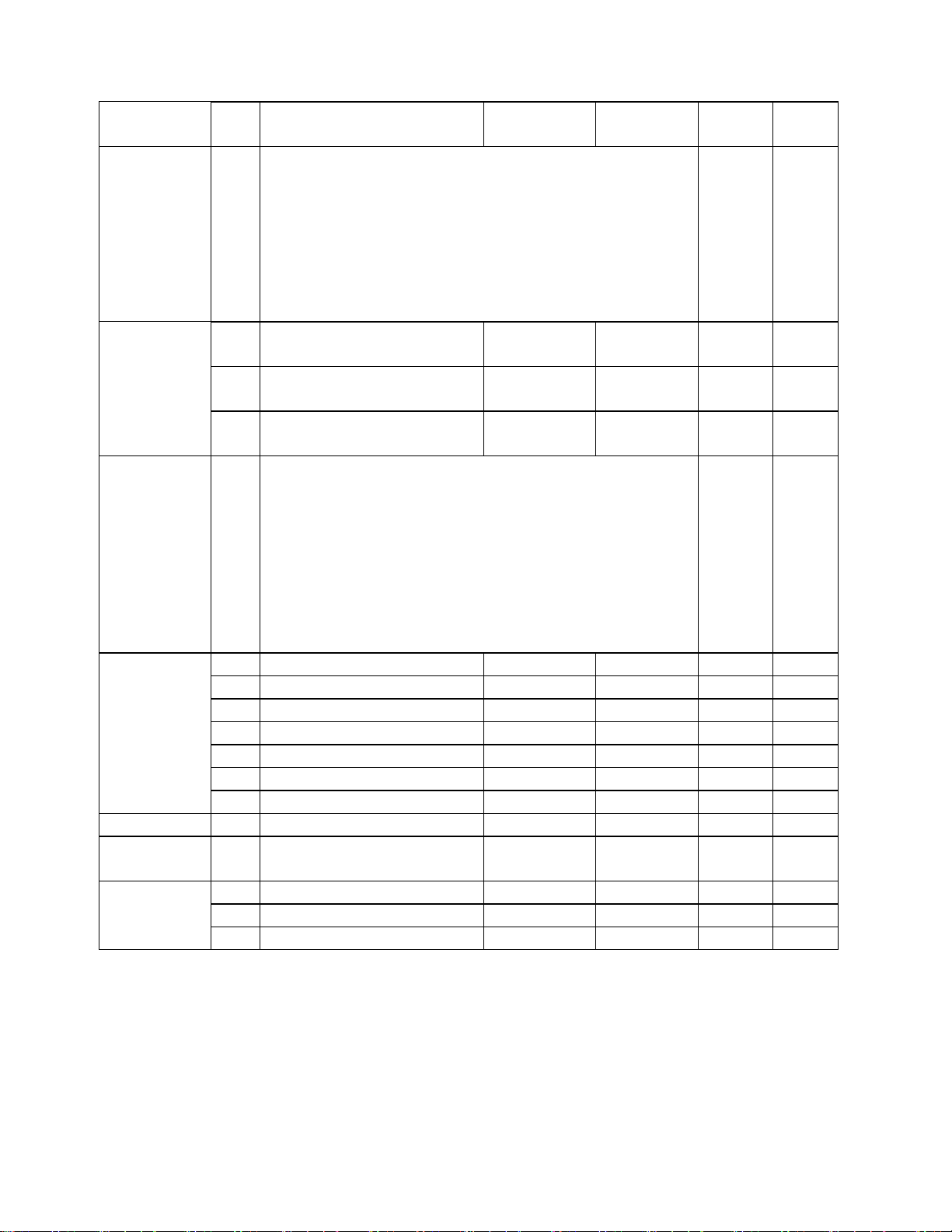
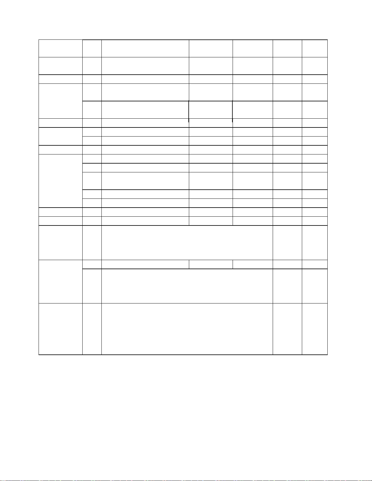
TECO-Westinghouse FLUXMASTER 100 Series User manual

i
Maintenance and Operations Manual
Table of Contents
Foreword..........................................................................................................1
Precautions for Operation................................................................................3
Environmental Precautions..............................................................................5
General Information.........................................................................................7
Specifications...................................................................................................9
Wiring.............................................................................................................11
Keypad Operation..........................................................................................14
Parameter List................................................................................................15
Function Description......................................................................................23
Fault Codes....................................................................................................53
Maintenance Section…………………………………………………………….. 58
Dimensions…………………………………………………………………………63
Braking Resistors…………….……………………………………………………64

1
Foreword
To fully employ all the functions of this Inverter, and to ensure the safety for its users, please
read through this operations manual in detail. Should you have any further questions, please
contact your local TECO-Westinghouse distributor or regional sales representative.
: Please use Precaution with this Product
The Inverter is a power electronic device. For safety reasons, please read carefully those
paragraphs with “WARNING” or “CAUTION” symbols. They are important safety precautions
to be aware of while transporting, installing, operating and examining the Inverter. Please
follow these precautions to ensure your safety.
WARNING Personal injury may result from improper operation.
CAUTION The Inverter or mechanical system may be damaged by improper
operation.
WARNING
zDo not touch the PCB or components on the PCB right after power has been turned
OFF. Charging indicator light must be OFF before examining the components.
zDo not attempt to wire circuitry while power is ON. Do not attempt to examine the
components and signals on the PCB while the Inverter is operating.
zDo not attempt to disassemble or modify internal circuitry, wiring, or components of
the Inverter while power is ON.
zThe Inverter frame must be connected to ground with a suitably rated cable,
connected to the Ground Terminal on the Inverter.
CAUTION
zDo not attempt to perform dielectric strength test to internal components of the
Inverter. The Inverter contains sensitive semiconductor devices that are vulnerable
to high voltages.
zDo not connect the output terminals: T1, T2 and T3 to AC power input.
zThe CMOS IC on the primary PCB of the Inverter is vulnerable to static electrical
charges. Do not handle the primary PCB without the use of proper anti-static
equipment.

2
Examination Before Installation
Every FM100 has been fully tested and examined before shipment. Please carry out the
following examination procedures after unpacking your Inverter.
zCheck to see if the model number of the Inverter matches the model number of the
Inverter that you have ordered.
zCheck to see whether any damage occurred to the Inverter during shipment. Do not
connect the Inverter to the power supply if there is any sign of damage.
Report any damage that may have occurred to the Inverter during shipment to the freight
carrier and your local TECO-Westinghouse distributor or regional sales representative.

3
Precautions for Operation
Before Turning ON Power
CAUTION
Choose the appropriate power source with correct voltage settings for the input
voltage specification of the Inverter.
WARNING
Special care must be taken while wiring the primary circuitry panel. The L1, L2 and L3
terminals must be connected to the input power source and must not be mistakenly
connected to T1, T2 or T3 output terminals. This may damage the Inverter when the
power is turned ON.
CAUTION
zDo not attempt to transport the Inverter by the front cover. Securely hold the
Inverter by the heatsink mounting chassis to prevent the Inverter from falling.
Failure to do so may cause personal injury or damage to the Inverter.
zInstall the Inverter onto a firm metal baseplate or a non-flammable type material.
Do not install the Inverter onto or nearby any flammable material.
zAn additional cooling fan may need to be installed if several Inverters are installed
into one control panel. The temperature inside an enclosed panel should be below
104oF (40oC) to avoid overheating.
zTurn OFF the power supply before performing any work in the control panel. Carry
out installation procedures according to instructions. This will help avoid a situation
that may result in an operational malfunction.
zThis product is not provided with overspeed protection.
zThis product is only intended for use in a clean dust and moisture free environment.
When Power is Applied
WARNING
Do not attempt to install or remove input or output connectors of Inverter while the
power supply is turned ON. Otherwise, the Inverter may be damaged due to the
surge peak caused by the insertion or removal of power.

4
Under Operation
WARNING
Do not use a separate device to switch the motor ON or OFF during operation. The
Inverter may experience an overcurrent failure.
WARNING
zTo avoid personal injury caused by electrical shock, do not remove the front
cover of the Inverter while the power is ON.
zWhen the automatic restart function is enabled, the motor and machinery will
restart automatically.
CAUTION
zDo not touch the heatsink base during operation.
zThe Inverter can be easily operated at low and high speed ranges. Please
reconfirm the operating range of the motor and machinery you are controlling.
zDo not examine the signals on the PCB of the Inverter during operation.
zAll Inverters are properly adjusted and factory set before delivery.
CAUTION
Do not proceed with disassembly or examination of the Inverter before ensuring that
the power is OFF and that the Power LED has extinguished.
Performing an Examination or Maintenance
CAUTION
The environment ambient temperature should be within 14OF ~ 104OF (-10OC ~
40OC), with humidity under 95% non-condensing. The Inverter should be free from
dripping water and metal dust.

5
Environmental Precautions
Avoid direct sunlight Keep away from corrosive
gases and liquids Keep away from oil,
grease and gas
Keep away from salty
environments Keep away from rain
and dripping water Avoid dusty environments
Avoid excessive vibration
A
void excessive direct heat Avoid high temperature
environments
Keep away from high
electrical magnetic waves Keep away from
radioactive matter
Keep away from
flammable material
oil

6
Hardware Instructions and Installation
Operating Conditions
The installation site of the Inverter is important. It has a direct relationship on the functionality
and life span of your Inverter. Please carefully consider the following requirements when
choosing an installation site:
zMount the unit vertically.
zInverter ambient temperature should be within
zEnvironment ambient temperature should be within 14oF ~ 104oF (-10oC ~ 40oC).
zAvoid placing the Inverter close to any heating equipment.
zAvoid dripping water and humid environments.
zAvoid direct sunlight.
zAvoid oil, grease and gas.
zAvoid contact with corrosive gases and liquids.
zPrevent foreign dusts, flocks, or metal scraps from contacting the Inverter.
zAvoid electric magnetic interference (soldering or power machinery).
zAvoid excessive vibration. If vibration cannot be avoided, an anti-vibration mounting
device should be installed to reduce vibration.
zIf the Inverter is installed in an enclosed control panel, please add additional cooling
using an external fan. This will allow additional airflow and cooling.
zPlacement of external fans should be directly over the top of the Inverter.
zFor proper installation of the Inverter, you must place the front side of the Inverter facing
front and the top of the Inverter in the up direction for proper heat dissipation.
Ventilation &
Installation Direction
Front & Side Views

7
General Information:
General
The FM100 series is a General Purpose Inverter that incorporates a high efficiency Pulse Width
Modulated (PWM) design and advanced IGBT technology. The output closely approximates a
sinusoidal current waveform to allow variable speed control for any conventional squirrel cage
induction motor.
Receiving
This unit has been put through demanding tests at the factory prior to shipment.
Before unpacking please check the following:
1. Identify the description of the product found on the label with your purchase order.
2. Inspect for shipping damage. Serious damage to the carton may indicate damage to
the unit.
Please check the following after unpacking:
a. Check to see if the specifications (current & voltage) on the side of the unit match your
application requirement.
b. Check all the electrical connections and screws.
c. Verify that there is no visible damage to any of the components.
IMPORTANT: If any part of the Inverter or the shipping carton is damaged, please notify
the carrier and your distributor immediately.

8
Installation:
Location
Choosing the proper installation location for the Inverter is imperative in order to achieve the
maximum specified performance and operation from the FM100. The Inverter should always
be installed in areas where the following conditions exist:
•Good ambient operating temperature:
14oF to 104oF (-10oC to 40oC)
•Enclosure Rating: NEMA 1 for all models. If the Inverter is placed in another enclosure,
please provide additional cooling using an external fan.
•Protected from rain and moisture.
•Shielded from direct sunlight.
•Free from metallic particles and corrosive gas.
•Free from excessive vibration. (Below 0.5G)
Positioning
For effective ventilation and maintenance of the Inverter, provide sufficient clearance (as shown in
Figure 2.1) around the Inverter. The Inverter must be installed with heatsink fins oriented vertically.
Figure 2.1
⇔Allow 4.72in. (12cm)
clearance on both sides of
the enclosure.
⇔Be sure to allow the air to
move freely through the
heatsink area.

9
Basic Specification:
1 / 3 Phase 200 ~ 240 Volts
230 Volts
FM100-xxx-N1 2P5 201 202 203 205 208 210 215 220 230
Horsepower HP .50 1 2 3 5 7.5 10 15 20 30
Rated Current A 3.1 4.5 7.5 10.5 17.5 26 35 49 64 87
Output KVA 1.2 1.7 2.9 4.0 6.7 9.9 13.3 18.7 24.4 33.2
Input Voltage 1 / 3 Phase* 200 ~ 240 Volts, + / -10% 50 / 60Hz, + / -5%
Output Voltage 3 Phase 200 ~ 240 (Proportional to Input Voltage)
Weight (lbs.) 3.1 3.1 5.5 8.8 8.8 15.0 15.7 27.1 27.6 30.4
Power Loss
Ride Through (s) 1111122222
* Note: .50 - 3HP are rated for 1 / 3 Phase Input. 5HP and above are 3 Phase Input only.
3 Phase 380 ~ 460 Volts
460 Volts
FM100-xxx-N1 401 402 403 405 408 410 415 420 430
Horsepower HP 1 2 3 5 7.5 10 15 20 30
Rated Current A 2.3 3.8 5.2 8.8 13 17.5 25 32 48
Output KVA 1.7 2.9 4.0 6.7 9.9 13.3 19.1 24.4 36.6
Input Voltage 3 Phase 380 ~ 460 Volts, + / -10% 50 / 60Hz, + / -5%
Output Voltage 3 Phase 380 ~ 460 Volts (Proportional to Input Voltage)
Weight (lbs.) 5.3 5.5 8.4 8.8 15.4 16.1 27.1 27.6 29.8
Power Loss
Ride Through (s) 111122222

10
Functional Specification:
Carrier Frequency 1 - 12KHz
Frequency Control Range 0.1 - 400Hz
Frequency Accuracy Digital: 0.01%; Analog: 0.4%
Frequency Resolution Digital Keypad Reference: 0.01Hz (0 - 99.9Hz); 0.1Hz (100 - 400Hz)
Frequency Setting Signal 0 - 5VDC, 0 - 10VDC, 0 - 20mA, 4 - 20mA
Accel / Decel Time 0.1 - 3600 Seconds (Two Independent Accel / Decel or S-Curve Settings)
Braking Torque Approx. 20% (Braking Transistor Unit is built-in to 10HP units and below)
Control
Character-
istics
V/F Pattern 18 Preprogrammed Patterns (One Custom Pattern)
Instantaneous Overcurrent Approximately 200% of Rated Current
Overload Protection 150% Rated Output Current for 60 Seconds
Motor Overload Electronic Thermal Overload Relay
Overvoltage 230V Series: (DC Bus exceeds 427V)
460V Series: (DC Bus exceeds 854V)
Undervoltage 230V Series: (DC Bus Voltage drops below 200V)
460V Series: (DC Bus Voltage drops below 400V)
Momentary Power Loss .7 - 2 Seconds: FM100 can be restarted with Speed Search
Protection
Function
Heatsink Overheat Protected by Thermostat
Operation Signal Forward / Reverse Operation, by Keypad or Hardwired Contact,
Multiple Individual Commands
Reset Released Protection while the Protect Function is Operating
Input
Signals Multi-Functional
Inputs Refer to Function Illustration in Fn_56
Multi-Functional
Output Refer to Function Illustration in Fn_61
Output
Signal Fault Contact 250VAC 1A, 30VDC 1A or less
Built-in Function Frequency Reference Bias / Gain; Upper and Lower Limit; Manual Torque
Boost; Frequency Meter Gain; Auto Restart; Skip Frequency; S-Curve
Accel / Decel; Carrier Frequency Adjust; Communication Link Function
Digital Keypad Monitor 4 Digit 7 Segment LED Display Indicates: Frequency; Output Frequency;
Speed; Output Current; Output Voltage; Bus Voltage; Rotating Direction
Operating
Conditions
Analog Output Monitor 0 - 10VDC Analog Output, Possible to Select: Output Frequency; Setting
Frequency; Output Voltage; Bus Voltage
Location Indoor (Protected from Corrosive Gases and Dust)
Ambient Temperature +14oF ~ 104oF (-10oC ~ 40oC)
Humidity 0 - 95% (Non-Condensing)
Environ-
mental
Conditions Vibration 0.5G (4.9m/s2)
Enclosure NEMA 1
UL UL508C

11
Wiring & Remote Operating Functions:
External Connections Braking
Resistor
P Inverter R Thermal Overload Relay
MC
ΟΟ II
ΟΟ II
ΟΟ II
Thermal Relay
On Off MC (E)
II
II RS232 / 485
MC Surge Arrestor TM2 CON12 CONNECTOR *1
FWD ΟΟ 3
REV ΟΟ 4
SP1 ΟΟ 6
SP2 ΟΟ 7 Keypad
SP3 ΟΟ 8
RES ΟΟ 9
COM 5
CON1
Freq Command
Potentiometer ΟΟFault Relay (NO or NC)
10K / 2W 250VAC 1A (30VDC 1A)
11 + Sync Multi-Function O/P
10 - Sync (35VDC 50mA)
Freq. Meter
*1: For .50HP 230 Volt Units, please use Jumper to short Pin 1 and Pin 2 of
CON12 when CON12 is not used.
L1 (R)
L2 (S)
L3 (T)
T1 (U)
T2 (V)
T3
(
W
)
12
13
14
15
14
+
_
1
2

12
General Wiring Instructions:
Note:
The FM100 can be completely controlled by the Digital Keypad. If you chose to use the TM2
control terminal strip, please see the following instructions.
Frequency Meter
Speed Pot
Reset
Multi-Function
Input Terminals
Common
Forward / Reverse
Fault
(T1) (T2) (T3)
Motor Connections
Brake Resistor
Input Power
(L1) (L2) (L3)
L1
L2
L3 P R T1 T2 T3

13
Function Description for the Main Circuit Power Terminals (TM1)
SYMBOL FUNCTION DESCRIPTION
L1 (R) Input Terminals of AC Line Power: 230 or 460 Volt
L2 (S) Single Phase: L1 / L2
L3 (T) Three Phases: L1 / L2 / L3
P
RExternal Braking Resistor Terminals
T1 (U)
T2 (V)
T3 (W) Output Terminals to Motor
Function Description for the Control Terminals (TM2)
SYMBOL FUNCTION DESCRIPTION
1 Fault Relay Output Terminals: (Fn_97, 98)
2TRIP
RELAY Contact Rating: 250VAC / 1A (30VDC / 1A)
3FWD
4REV
Operation Control Terminals (Fn_03)
5 COM Ground Common for Terminals 3 / 4 / 6 / 7 / 8 / 9
6 SP1
7 SP2
8 SP3 Multi-Function Input Terminals (Fn_56)
9 RESET Reset Terminal (Fn_16)
10 SYN- Negative Terminal for Multi-Function Output (Fn_61)
11 SYN+ Positive Terminal for Multi-Function Output (Fn_61)
12 + +5V Power Terminal of Potentiometer (Pin 3)
13 Analog Analog Freq. Signal Input Terminal (Fn_26)
Input Positive Terminal
0 - 5VDC, 0 - 10VDC, 4 - 20mA
14 _
FM - Analog Common Terminal for Analog Frequency
Common Negative Terminal
0 - 5VDC, 0 - 10VDC, 4 - 20mA
15 FM + Analog Multi-Function Output Terminal (Fn_46)
Output (+) Range of Output Signal: 0 - 10VDC

14
Keypad Operations:
Keypad Illustration
Freq. Ref. Controlled by TM2 or VR Forward Run
(Fn_11 = 1 / 2 / 3)
RUN/STOP Signal is on ΟΟΟΟReverse Run
(Fn_10 =1) SEQ FRQ FWD REV
DISPLAY Hz or ΟΟDisplay Voltage Value
RPM Hz/RPM VOLT
Light On: Program Mode ΟΟDisplay Current Value
FUN AMP
Run / Stop Mode Selection Key
Command Key Scroll Arrow Keys
Forward / Reverse
Command Key Digit Selection Key
Speed Pot
Adjustment FREQ. SET Data / Write key
Keypad Function:
RUN
STOP
DSPL
FUNC
FWD
REV
<
RESE
DATA
ENTE
DATA
ENTER
<
RESET
FWD
REV
RUN
STOP DSPL
FUNC
⇔RUN / STOP Button used for START / STOP Commands from the Keypad
⇔DSP / FUN Button used for Displaying Functions and Monitors
⇔FWD / REV Button used for Forward / Reverse Commands from the Keypad
⇔< / RESET Button used for moving Diagonally and Resetting the Drive
⇔DATA / ENTER used for Reading and Entering Functions
⇔Arrows are used for Navigating and Changing Parameters

15
Parameter List
Function Fn_
xx Description Engineering
Units Range Factory
Setting Page
Drive Capacity 0 Drive Capacity Selection 1 1 - 18 *3 23
Accel Time 1 Accel Time 1 0.1 sec 0.1 - 3600
sec 10 sec 23
Decel Time 2 Decel Time 1 0.1 sec 0.1 - 3600
sec 10 sec 23
Stop / Start
Control TM2 3 xx00 : FWD / STOP, REV / STOP
xx01 : FWD / REV, RUN / STOP
xx10 : 3-Wire Start / Stop Control
x0xx : REV Command Enable
x1xx : REV Command Disable
0xxx : Setting Frequency will remain at last Output Frequency
when
Inverter stops and Fn_11 = 3
1xxx : Setting Frequency will be 0 (zero) when Inverter stops
and
Fn_11 = 3
0000 24
Parameter
Lockout 4 xxx0 : Enable (Fn_17 - 25)
xxx1 : Disable (Fn_17 - 25)
xx0x : Enable (Functions except Fn_17 - 25)
xx1x : Disable (Functions except Fn_17 - 25)
0000 25
V/Hz Pattern 5 V/Hz Pattern Selection 1 0 - 18 9 / 0 25
6 Frequency Upper Limit 0.01Hz 0 - 400Hz 60 / 50 27Frequency
Limit 7 Frequency Lower Limit 0.01Hz 0 - 400Hz 0Hz 27
Target Speed 8 Target Frequency Setting 0.01Hz 0 - 400Hz 0Hz 27
Target Speed
Bandwith 9 Frequency Setting Detection
Width (+ / - F9 / 2) 0.01Hz 0 - 30Hz 0Hz 27
START / STOP
Selection 10 0 : Keypad
1 : TM2 028
Frequency
Command
Selection
11 0 : Controlled by (Fn_25) Master Reference at Keypad
1 : Controlled by Keypad Frequency Setting Potentiometer
2 : Controlled by TM2 (Speed Pot)
3 : Controlled by Preset Speeds or Multi-Function Inputs
(Terminals 6 / 7 / 8)
028

16
Function Fn_
xx Description Engineering
Units Range Factory
Setting Page
Stall
Prevention 12 xxx0 : Stall Prevention during Accel enable
xxx1 : Stall Prevention during Accel disable
xx0x : Stall Prevention during Decel enable
xx1x : Stall Prevention during Decel disable
x0xx : Stall Prevention during Run enable
x1xx : Stall Prevention during Run disable
0xxx : Stall Prevention Decel TIme set by Fn_02
1xxx : Stall Prevention Decel Time set by Fn_15
0000 29
13 Stall Prevention starting level
during Accel 1% 30 - 200% 110% 29
14 Stall Prevention Level during
Run 1% 30 - 200% 160% 29
Stall
Prevention
15 Decel Time during Stall
Prevention 0.1 sec 0.1 - 3600
sec 3 sec 29
Direct Start &
Reset and
Numbers of
Input Signal
Scanning
16 xxx0 : Direct Start enable when remote RUN command ON
xxx1 : Direct Start disable when remote RUN command ON
xx0x : Reset effective only if remote RUN command OFF
xx1x : Reset effective disregard of remote RUN command
condition
00xx : TM2 will scan 10 times
01xx : TM2 will scan 5 times
10xx : TM2 will scan 3 times
11xx : TM2 will scan 1 time
0000 30
17 Preset Speed 1 0.01Hz 0 - 400Hz 5.00Hz 30
18 Preset Speed 2 0.01Hz 0 - 400Hz 10.00Hz 30
19 Preset Speed 3 0.01Hz 0 - 400Hz 20.00Hz 30
20 Preset Speed 4 0.01Hz 0 - 400Hz 30.00Hz 30
21 Preset Speed 5 0.01Hz 0 - 400Hz 40.00Hz 30
22 Preset Speed 6 0.01Hz 0 - 400Hz 50.00Hz 30
Preset Speeds
23 Preset Speed 7 0.01Hz 0 - 400Hz 60.00Hz 30
Jog Speed 24 Jog Frequency Reference 0.01Hz 0 - 400Hz 2.00Hz 31
Master
Frequency 25 Master Frequency Reference
from the Keypad 0.01Hz 0 - 400Hz 5.00Hz 31
26 Frequency Reference 0.01Hz 0.0 - 400Hz 0Hz 32
27 Voltage Reference Ratio 1 0.1% 0 - 100.0% 0% 32
Analog Input
Frequency
Command 28 Voltage Reference Ratio 2 0.1% 0 - 999.9% 100% 32

17
Function Fn_
xx Description Engineering
Units Range Factory
Setting Page
Direction + / - 29 Positive / Negative Direction 1 0 : Positive
1 : Negative 032
Power Voltage 30 Input Voltage of Power Supply 0.1V 200 - 480V *3 33
31 Momentary Power Loss Ride
Through Time 0.1 sec .7 - 2 sec 0.5 sec 33Momentary
Power Loss
Ride Through 32 xxx0 : Disable
xxx1 : Enable 033
33 Reserved for Future Use 33
34 Auto Restart Time 0.1 sec 0 - 800 sec 0 sec 33Auto Restart 35 No. of Auto Restart Attempts 1 0 - 10 0 33
Motor Poles 36 No. of Motor Poles 2P 2 - 8 pole 4P 33
V/Hz Pattern 37 Max. Frequency 0.01Hz 50 - 400Hz 60 / 50Hz 34
38 Max. Voltage Ratio 0.1% 0 - 100% 100% 34
39 Mid. Frequency 0.01Hz 0.11 - 400Hz 3.0 /
2.5Hz 34
40 Mid. Voltage Ratio 0.1% 0 - 100% 7.5% 34
41 Voltage Ratio at 0.1Hz 0.1% 0 - 100% 7.5% 34
Starting Freq. 42 Start Frequency Adjustment 0.01Hz 0.1 - 10Hz 1Hz 35
Carrier Freq. 43 Carrier Frequency Adjustment 1 0 - 15 14 35
Stopping Mode
and Braking
Resistor
Protection
44 xxx0 : Decel to Stop
xxx1 : Coast to Stop
xx0x : Braking Resistor Thermal Protection disable
xx1x : Braking Resistor Thermal Protection enable
0000 35
45 Gain : Analog Output 1% 0 - 200% 100% 36Multi-Function
Analog Output
Selection
(Terminals)
(14 & 15)
46 0 : Output Frequency (Fn_6 Max.)
1 : Set Frequency (Fn_6 Max.)
2 : Output Voltage
3 : Bus Voltage
036
Display Mode 47 xxx0 : Output Voltage (VAC) Display disable
xxx1 : Output Voltage (VAC) Display enable
xx0x : Bus Voltage (VDC) Display disable
xx1x : Bus Voltage (VDC) Display enable
x0xx : Output Current (IAC) Display disable
x1xx : Output Current (IAC) Display enable
0000 36

18
Function Fn_
xx Description Engineering
Units Range Factory
Setting Page
Dynamic
Braking and
Priority of
Stopping and
Speed Search
& AVR Control
48 xxx0 : Enhanced Braking Capacity
xxx1 : Standard Braking Capacity
xx0x : STOP Key effective in Remote Control Mode
xx1x : STOP Key ineffective in Remote Control Mode
x0xx : Speed Search controlled by Terminals on TM2
x1xx : Speed Search effective during Inverter Start
0xxx : AVR Function effective
1xxx : AVR Function ineffective
0000 37
Accel / Decel 49 Accel Time 2 0.1 sec 0.1 - 3600
sec 10.0 sec 37
Time 2 50 Decel Time 2 0.1 sec 0.1 - 3600
sec 10.0 sec 37
51 Display Mode Selection 1 0 - 5 0 37Display mode 52 Engineering Units 1 0 - 9999 1800 37
DC Braking 53 DC Braking Time 0.1 sec 0 - 25.5 sec 0.5 sec 38
54 DC Braking Injection Freq. 0.1Hz 0.1 - 10Hz 1.5Hz 38
55 DC Braking Level 0.1% 0 - 20% 8% 38
Multi-Function
Inputs 56 Multi-Function Input 1
(Terminal 6) 00 : SP1
01 : SP2
02 : SP3
00 38
57 Multi-Function Input 2
(Terminal 7) 03 : Jog
04 : Accel / Decel Time
Selection
05 : External Emergency
Stop
01 38
58 Multi-Function Input 3
(Terminal 8) 06 : External Coast Stop
07 : Speed Search 02 38
59,60 Reserved for Future Use 38
Multi-Function
Output 61 Multi-Function Output 1
(Terminals 10 & 11) 00: Run Mode
01: At Target Speed 00 40
02: Set Frequency
(Fn_08/09) 40
03 Frequency Detection
(Fn_08)40
62 Reserved for Future Use 04 Frequency Detection
(Fn_08)40
63 Reserved for Future Use 05 Overcurrent Detection 40
06 Change 00 - 05 (NO) (NC) 40
This manual suits for next models
19
Other TECO-Westinghouse Inverter manuals

TECO-Westinghouse
TECO-Westinghouse F510 Series User manual

TECO-Westinghouse
TECO-Westinghouse E510-201-H-U Installation and operation manual

TECO-Westinghouse
TECO-Westinghouse MA7200 PLUS Instruction manual

TECO-Westinghouse
TECO-Westinghouse F510 Series User manual

TECO-Westinghouse
TECO-Westinghouse PA7300 Series User manual

TECO-Westinghouse
TECO-Westinghouse A510 User manual

TECO-Westinghouse
TECO-Westinghouse E510 Installation and operating manual

TECO-Westinghouse
TECO-Westinghouse L510-1P2-H1-U Installation and operation manual

TECO-Westinghouse
TECO-Westinghouse MA7200 PLUS User manual

TECO-Westinghouse
TECO-Westinghouse E510-2P5-H-U User manual