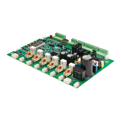
TECORP ELECTRONIC HC2-E1000 Series User manual

HC2-E1000 SERIES
- 0 -
Thank you for using E1000 series, economical AC motor speed
controller made by TECORP E ECTRONIC CO., TD
In order to make use of the functions full on the AC motor speed
controller and ensure safety of user, please read this instruction carefully
before installing, running, maintaining and checking AC motor speed
controller.
This instruction divides safety cautions into Danger and Warning,
please pay special attention to the symbols “ ” and “ ” and
their related content.
The symbol “ ” indicates incorrect operation, which can
cause death or serious injury to personnel.
The symbol “ ” indicates incorrect operation, which can cause
personnel injury or AC motor speed controller and mechanical system fault,
as determined by different situations, the caution affairs may lead to
serious consequence.
The figures in this instruction are for convenience with descriptions;
they may have slight differences compared to the products, and the
products update can also cause slight differences between the figures and
products, the actual sizes are subject to actual products.
Please notice that this operational instruction shall be delivered to the
end user, and be kept appropriately for further use of inspecting and
maintaining.
If you have questions, please contact us or our agents in time, you
will always receive our best attention.

HC2-E1000 SERIES
- 1 -
Contents
Chapter 1 Safety Cautions-------------------------------------------------2
1-1 Confirmation on Receiving ----------------------------------- 2
1-2 Moving and Installation---------------------------------------- 2
1-3 Wiring and Junction -------------------------------------------- 4
1-4 Power on and Commissioning-------------------------------- 5
1-5 Check and Maintenance --------------------------------------- 6
1-6 Exception Processing ----------------------------------------- 7
1-7 Scrapping Processing------------------------------------------ 7
Chapter 2 Product Introduction------------------------------------------8
2-1 Unpacking Inspection------------------------------------------ 8
2-2 Model Description--------------------------------------------- 8
2-3 Product Specifications ---------------------------------------- 9
2-4 Product Models-------------------------------------------------10
2-5 Dimensions------------------------------------------------------10
Chapter 3 Wiring and Operation--------------------------------------- 11
3-1 Wiring Diagram------------------------------------------------11
3-2 Display Panel---------------------------------------------------11
3-3 Parameter Setting ----------------------------------------------12
Chapter 4 Table of Functional Parameters---------------------------13
Chapter 5 Fault Alarm and Solutions ---------------------------------17

HC2-E1000 SERIES
- 2 -
Chapter 1 Safety Cautions
1-1 Confirmation on Receiving
Warning
All the products have gone by strictly checking and testing before
delivery, but considering transportation, please verify:
Whether AC motor speed controller is distorted or damaged
during transportation, do not install broken AC motor speed
controller, and it may cause personnel injury, please inform our
agent in time.
Whether the package is integrated, accessories and user’s
instruction are contained, especially the user’s instruction and
guarantee card, please keep those for reference of further
maintenance
Whether the product is in accordance with the specifications, and
whether there are unusual phenomena inside or outside AC motor
speed controller.
1-2 Moving and Installation
Warning
When moving the product, please use proper moving instruments
to preventAC motor speed controller from damage.
When moving AC motor speed controller, please fasten the
bottom of AC motor speed controller, holding the cover plate
directly may lead to dropping and cause personnel injury or AC
motor speed controller damaged.
Please do not install AC motor speed controller on combustible
substance, installing the convert directly on the combustible
substance or near to combustible material may cause fire
accident.
Please verify whether installation of AC motor speed controller is
correct.
Please choose a safe location to install AC motor speed controller,
and operation environment is shown as follows.

- 3 -
Ambient temperature: -10℃-40℃〈non-freezing〉.
Ambient humidity: max. 95% relative humidity
〈non-condensing〉
Ambient environment: indoors,〈no corrosive gas, combustible gas,
oil mist and dust. Please keep off sunlight〉.
Altitude: lower than 1000m
Vibration: max. 0.5G
Please make sure that the mounted substance can load with AC
motor speed controller’s weight and prevent it from falling, and
make sure that the installation site is safe and reliable. Do not
allow children and unauthorized personnel approaching AC
motor speed controller.
Please make sure that the screws are fixed, fastened and locked
firmly in accordance with user’s instruction of the manual, to
preventAC motor speed controller from falling.
During installation, prevent screws, wire pieces and other
electricity conductive material from falling in AC motor speed
controller. Otherwise, AC motor speed controller may be
damaged, or a serious accident may take place.
If two and more AC motor speed controller is installed in one
control cabinet, please install them according to the instruction of
the manual. It is required to keep enough space, and add extra
heat sinkers for airflow in the cabinet. That will lower 40℃of the
temperature in the cabinet. Overheating may cause AC motor
speed controller broken, fire or other accident.
AC motor speed controller shall be installed by professional
personnel.

HC2-E1000 SERIES
- 4 -
1-3 Wiring and Junction Warning
Please do not damage the wires. Let the wires bear weight or be
clamped may damage the wires and cause an electric shock.
Do not install the phase-shifting capacitor, surge absorber or
noise filter in output terminal of AC motor speed controller,
otherwise may cause AC motor speed controller fault.
Do not install switch devices in the output terminal of AC motor
speed controller such as the air switch and contactor. If it is for
technologic demand, please ensure that AC motor speed
controller is switching without output.
Please wire separately power wire and control wire for preventing
interference.
Danger
Please ensure that the power is off before Junction.
The wiring work shall be done by qualified electricians.
Please wire in accordance with the user’s instruction of the
manual.
The grounding connection shall be installed properly in
accordance with relative regulations in the user’s instruction.
Otherwise it may cause an electric shock or fire.
Please use independent power supply for AC motor speed
controller. Never use the same power supply with strong
interference equipment like electric welder.
Please do not touch the bottom plate with wet hand. Otherwise
you may get an electric shock.
Please do not touch the terminal directly. Do not connect with AC
motor speed controller input/output cables with the cover panel.
Otherwise you may get an electric shock.
Please make sure that voltage of the power supply and voltage of
AC motor speed controller are the same, otherwise it may cause
AC motor speed controller fault or personnel injury.
Please make sure that power supply connects with the R·S·T
terminal but without the U.V.W terminal, otherwise it may cause

- 5 -
the internal fault of AC motor speed controller.
Please do not test AC motor speed controller on pressure
resistance. Otherwise it may cause the internal fault of AC motor
speed controller.
Please install accessories such as brake units, brake resistors in
accordance with the user’s instruction; otherwise it may cause AC
motor speed controller fault or fire.
Please ensure that the screws of the terminals are firmly locked,
otherwise it may cause AC motor speed controller fault.
1-4 Power on and Commissioning
Warning
Please ensure that the front cover is installed before the power is
on. During the power transmission, please do not remove the
cover.
Please ensure that the power cables and signal cables are
connected correctly, otherwise it may cause AC motor speed
controller damaged.
Please ensure all of the parameters are set correctly before
running.
Before running, please ensure machine not to damage running
equipments. It is recommended to take running with idle load.
Please provide an emergency stop switch when stop function
setting is unavailable.
Do not use electromagnetic contactor to start up and shut down
AC motor speed controller, otherwise it may affect the life of AC
motor speed controller
Danger
When fault restart function is set. Please do not approach
equipment because the equipment may automatically restart after
running stop.
Please verify the use range of motors and machines. Exceeding
their use range will cause motor and machine fault.
Please do not change the parameter settings of AC motor speed

HC2-E1000 SERIES
- 6 -
controller casually during running.
Please do not touch the heat sink and brake resistor, otherwise
you may get burned.
Do not use wet hands to touch bottom plate and to operate
switches and keys. Otherwise you may get an electric shock or
injury.
Please do not link or withdraw motors during AC motor speed
controller running, otherwise it may cause AC motor speed
controller protected or fault.
1-5 Check and Maintenance
Warning
Please ensure that the power and indicating light is off before
checking and maintaining. Otherwise, you may get an electric
shock.
Before checking and maintaining, please touch a nearby metal
substance with your hand to eliminate the static electricity for
preventing AC motor speed controller from damage caused by
static electricity.
Please do not use Megohmmeter (insulation resistance) to test the
control circuit of AC motor speed controller.
Danger
Only authorized professional personnel can do check,
maintenance and replacement of the components, no other people
are allowed.
Please do check, maintenance and replacement of the components
according to appointed methods in the user’s instruction, strictly
prohibit modifying by your own. If you do so, you may get an
electric shock and injury or AC motor speed controller may get
damaged.

- 7 -
1-6 Exception Processing Danger
When the protection in AC motor speed controller is on, please
follow the fault display of AC motor speed controller to find out
causes and eliminate the fault, then reset and restart AC motor
speed controller. If the fault is not eliminated. Resetting and
restarting AC motor speed controller can cause AC motor speed
controller s or machine fault.
When AC motor speed controller fault takes place, please do not
treat it by your own, and contact our company and our
distributors.
1-7 Scrapping Processing
Warning
When AC motor speed controller is scrapped, please dispose it as
industrial rubbish, do not burn it up.

HC2-E1000 SERIES
- 8 -
Chapter 2 Product Introduction
2-1 Unpacking Inspection
In unpacking, please confirm the following:
Check whether the model type of AC motor speed controller is in
accordance with your order.
Check whether AC motor speed controller is damaged and related
accessories are completed.
If you find an omission or disagreement, please contact the suppliers.
2-2 Model Description
MODEL HC201D5E24F
INPUT 3PH 220V 50/60Hz
OUTPUT 3PH 220V 6.0A 150% 60s
RANGE 0.1~400Hz 1.5KW
HC2 □□□□ E □□ F
Version: F
Voltage: 24 (AC 200 ~ 240V)
Model: E1000
Capacity: 0.4~0.15KW

- 9 -
2-3 Product Specifications
Items Description
Input Rated Voltage,
Frequency Single/Three-phase 220V- 50/60Hz
Three-phase 380V-50/60Hz
Allowable Voltage
170~240V, 330~440V
Output
Allowable Voltage
170~240V, 330~440V
Frequency 0.10~400.0Hz
Control Mode V/F control
Display
Five-digit LED display, Indicator display;
Display setup frequency, Output frequency,
Output current, DC voltage, Module
temperature, Running state, and fault
Control Function
Frequency Setup
Digital setting: 0.01 Hz. Analog setup: 0.1%
of maximum output frequency
Frequency
Accuracy 0.1Hz
V/F Control Changeable V/F curve by setting
Torque Control Auto raising torque by loading condition;
Manual increase: enable to set 0 to 20 % of
raising torque
Input Terminal 4 multi-function input, take 15 speed control,
process, 2 sets of acceleration/deceleration
Output Terminal
1 set of alarm
Time Setup 0~999.9s for speed up / down
Other Function Analog input 0~10V, 8 steps of multi-speed,
auto stable voltage
Environment
Temperature -10℃to 40℃(non-freezing)
Humidity Max. 95% (non-condensing)
Altitude Under 1000m
Vibration Max. 0.5G
Structure
Cooling Mode Compulsory cooling
Protection Level IP 20

HC2-E1000 SERIES
- 10 -
2-4 Product Models
2-5 Dimensions
Unit: cm
Model Power
Output
Capacity
KVA
Output
current
(A)
Overload
capacity
(60s) (A)
Applicable
motor
(KW)
Single/Three-phase 220V - 50/60Hz
HC200D4E24F
0.4 1.0 2.5 3.75 0.4
HC200D7E24F
0.75 2.0 5.0 7.5 0.75
HC201D5E24F
1.5 2.8 7.0 10.5 1.5
HC202D2E24F
2.2 4.4 11 16.5 2.2
Three-phase 380V - 50/60Hz
HC200D7E48F
0.75 2.2 2.7 4.05 0.75
HC201D5E48F
1.5 3.2 4.0 6.0 1.5
HC202D2E48F
2.2 4.0 5.0 7.5 2.2
Model L W H L1 W1
F KG
HC200D4E24F
141.5
85 113
130.5
74 5 1
HC200D7E24F
HC201D5E24F
HC202D2E24F
151
100
111.7
139.6
8.6
5.2
1.3
HC200D7E48F
HC201D5E48F
HC202D2E48F

- 11 -
Chapter 3 Wiring and Operation
3-1 Wiring Diagram
3-2 Display Panel
The display panel of Series E1000 consists of LED tubes, LED
indicators buttons and digital elements. The outline and functions as the
following:

HC2-E1000 SERIES
- 12 -
Display: setting frequency, running
frequency, electronic current, and
parameter value and alarm code.
Picture of the display panel
3-3 Parameter Setting
Properly setting the parameters will be running effectively. The
following is the example: 50HZ is changed into 25.00HZ.
The operation as the picture shown, pushing the shift button will switch
the twinkle position for change. This button has one-way circle function.
ENTER
ESC
50.00
F0
F000
F001
50.00
25.00
F002
F0
25.00
ENTER
ENTER
ESC
ESC
Status lamp: display the present status
Programming button
Function option / Save button
Jog button
Up
Switch button
Down
Running button
Stop button
Frequency setting button

- 13 -
Chapter 4 Table of Functional Parameters
F0 group - Basic parameters
Code
Parameter Settings Default
F000
Frequency setup
0: Digital
1: Keyboard POT
2: Analog
0
*1
F001
Main frequency 0.0 ~ 400.0Hz 50Hz
F002
Operation setup 0: Keyboard
1: IO terminal 0
F004
Maximum running
Frequency 50.0 ~ 400.0Hz 50Hz
*60Hz
F005
Rated frequency of motor
50 Hz 50 Hz
F006
Rated voltage of motor 220V 220 V
F008
Voltage of torque
compensation 0-30 6
F012
Acceleration time 0.1 ~ 3600s 10s *0.5s
F013
Deceleration time 0.1 ~ 3600s 10s *0.5s
F014
Upper frequency limit 0.0 ~ 400Hz 50Hz
F015
Lower frequency limit 0.0 ~ F014 0Hz
F1 group c Tool parameters
Code
Parameter Settings Default
F105
Stop mode 0: Speed down
1: Coast 0
F106
Start frequency of DC
braking 0 ~ 10Hz 6 Hz
F107
Start voltage of DC
braking 0 ~ 15% 10%
F109
Forward /Reverse
compensation time 0.0s 0s
F116
Deviation Frequency 0.0Hz
F117
Setting frequency gain 100

HC2-E1000 SERIES
- 14 -
Code
Parameter Settings Default
F120
Jog frequency 0.0 ~ 10.0Hz 0.2Hz *2Hz
F121
Jog acceleration time 0.01s ~ 60.00s 1s
F2 group – Input / Output parameters
Code
Parameter Settings Default
F200
Control mode 0: General
1: Knitting 0
F201
X1 terminal 1: Speed terminal 1
2: Speed terminal 2
3: Speed terminal 3
14: Instant stop
(normal open)
15: Instant stop
(normal close)
1
F202
X2 terminal 2
F203
X3 terminal 3 *16
F204
X4 terminal 4: Jog 4 *0
F216
Multi-speed frequency 1
0.0 ~ 400.0Hz
5Hz
F220
Multi-speed frequency 2 10Hz
F224
Multi-speed frequency 3 15Hz
F228
Multi-speed frequency 4 20Hz
F232
Multi-speed frequency 5 30Hz
F236
Multi-speed frequency 6 40Hz
F240
Multi-speed frequency 7 50Hz
F3 group – Advanced parameters
Code
Parameter Settings Default
F301
Carrier frequency
adjustment 0.0 ~ 12KHz
6KHz
*7KHz
F306
Reverse mode 0: enable 1: disable 0
F320
Unlock parameters 0: All parameters unlocked
2: Only this group unlocked
F321
Initialization
parameters 0: No action
1: Clear fault records

- 15 -
F4 group– Display parameters
Code
Parameter Default
F400
Output frequency
F401
Setup frequency
F403
Output voltage 219
F404
Voltage of DC bus 300
F405
Input terminal signal 0
F409
Fault record 1
F410
Fault record 2
F411
Fault record 3
F412
Fault record 4
Example: Multi-speed
Parameter F203 = 3 F202 = 2 F20 1= 1
Terminal X3 X2 X1
F001, F005 0 0 0
F216 0 0 1
F220 0 1 0
F224 0 1 1
F228 1 0 0
F232 1 0 1
F236 1 1 0
F244 1 1 1
※ Process of setting to default (the factory setting):
Set F321 for 1 →Press “Up” for 5 seconds →Show 2 on the display
→Press “Enter” →Show “------“ on the display →complete
Note: Some default values will be the value with*

HC2-E1000 SERIES
- 16 -
Chapter 5 Fault Alarm and Solution
Error
Code
Alarm Possible Reason Solution
OC-1
Over
Current in
Acceleration
1)Too short acceleration time
2)Disarrangement of V/F curve
3)Restart in running the motor
4)The capacity is not suitable
for the motor
5)Disarrangement of controller
1)Extend acceleration time
2)Correct V/F curve
3)Restart after running the
motor
4)Select a suitable motor
5)Check the connection
OC-2
Over
Current in
Deceleration
1)Too short deceleration time
2)Bigger potential load or
loading inertia
3)Less the capacity
4)Disarrangement of controller
1)Extend deceleration time
2)Add braking resistors
3)Select a suitable motor
4)Check the connection
OC
Over
Current in
Constant
speed
1)Too low voltage
2)Less the capacity
3)Restart in running the motor
4)Too heavy load
1)Check the input power
2)Check the phrase
3)Select a suitable motor
4)Restart after running the
motor
5)Check the connection
OE-1
Over
Voltage in
Running
1)Abnormal input voltage
2)Restart in running the motor
1)Check the input power
2)Restart after running the
motor
OE-2
Over
Voltage in
deceleration
1)Too short deceleration time
2)Bigger potential load or
loading inertia
3)Abnormal voltage
1)Extend deceleration time
2)Add braking resistors
3)Check the input power
OE
Over
Voltage in
constant
speed
1)Abnormal input voltage 1)Install input voltage
2)Check the input voltage

- 17 -
ELT
Failed to the
Capacity
Module
1)Sudden over current
2)Short circuit of the output or
grounding
3)Bad aeration or failed the fan
4)Failed the capacity bridge
1)Refer to error code OC
2)Check the connection
and the wire
3)Improve aeration or
replace the fan
OH
Over Heat
in Capacity
Module
1)Go beyond the requirement
2)Bad aeration or failed the fan
3)Failed to Detective circuit of
temperature
1)Improve the environment
2)Improve aeration or
replace the fan
OL Over load of
Motor
1)Disarrangement of V/F curve
2)Too low voltage
3)Run with low speed and high
torque for a long time
4)Set improper over loading
coefficient of the motor
5)The motor is blocked or too
high torque
1)Correct V/F curve
2)Check the input power
3)Select a specialized
inverter
4)Check the set parameters
5)Select a suitable motor
6)Check the connection
EMS
Failed to the
External
1)Failed to terminals of the
external equipment 1) Check the terminals
CPUE
Magnetic
disturbance
1)Taking serious disturbance 1)Push STOP/RESET button
-.E.r Failed to
EPROM
1)Taking serious disturbance of
EPROM in reading / writing
2)Failed EPROM
1)Push STOP/RESET button
STOP
Emergency
stop 1) locked the emergency stop
1)Push STOP/RESET button
twice to unlock the
emergency stop
Table of contents
Popular Controllers manuals by other brands
Allen-Bradley
Allen-Bradley PowerFlex 70 Reference manual
Polaris
Polaris Personalized Automated Control System owner's manual
Watlow
Watlow PM PLUS 6 user guide
Healthy wave
Healthy wave Multi-Wave PEMF Mat Controller operating instructions
Emerson
Emerson PeC C100 Hardware Implementation Guidelines
SMC Networks
SMC Networks LEFS Series Operation manual
