Read First
!
!Safety Information
Understand and follow operating instructions carefully.
Use the meter only as specified in this manual;
otherwise, the protection provided by the meter may be
impaired.
Identify hazardous conditions and actions that could
cause BODILY HARM or DEATH.
• If the equipment is used in a manner not specified by
the manufacturer, the protection provided by the
equipment may be impaired.
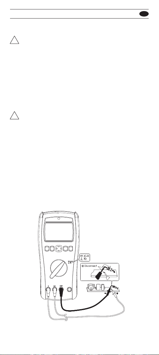
• Always use proper terminals, switch position, and
range for measurements.
• To reduce the risk of fire or electric shock, do not
expose this product to rain or moisture.
• Verify the Meter operation by measuring a known
voltage. If in doubt, have the Meter serviced.
• Do not apply more than the rated voltage, as marked
on meter, between terminals or between any terminal
and earth ground.
•To avoid false readings that can lead to electric shock
and injury, replace battery as soon as low battery
indicator blinks.
• Do not use Meter around explosive gas or vapor.
• When using test leads or probes, keep your fingers
behind the finger guards.
• Remove test lead from Meter before opening the
battery door or Meter case.
• Use caution with voltages above 30 Vac rms, 42 Vac
peak, or 60 Vdc. These voltages pose a shock
hazard.
• Probe assemblies to be used for MAINS measure
ments shall be RATED as appropriate for MEASURE
MENT CATEGORY III or IV according to IEC
61010-031 and shall have a voltage RATING of at
least the voltage of the circuit to be measured.
• Only replace the blown fuse with the proper rating as
specified in this manual.
• Do not attempt a current measurement when the
open voltage is above the fuse protection rating.
Suspected open voltage can be checked with voltage
function.
Warning
!
501 / 502 EN