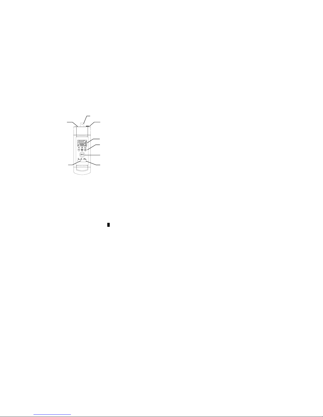
4. Front Panel Description
1. LCD: Measured values, unit, symbols and decimal points are displayed.
2. Input Socket: BNC connector for pH and mV.
3. Input Socket: Earphone (3.5mm) jack for temperature plug.
4. Input Socket: Earphone (2.5mm) jack for RS232 cable.
5. Push Buttons: Button for controlling meter.
6. Push Button: Turn on/off meter.
7. CAL Switch: Slide the switch to right to enter calibration mode.
8. °C/°F Switch: Slide the switch °C/°F to select the temperature unit.
4.1 Push Button functions
4.1.1 “HLD” Button:
Press the “HLD” button to enter the data hold mode, the “H” annunciator is displayed at
the top-right of display. When data hold mode is selected, the pH meter held the present
readings and stops all further measurements. Press the “HLD” button again to cancel data
hold mode, causing pH meter to resume taking measurements.
4.1.2 “MAX/MIN” Button:
Press the “MAX/MIN” button to enter the MAX, MIN, MAX-MIN, AVG recording
mode. (displays the Maximum reading, Minimum reading, “MAX-MIN” reading and
“AVG” reading in record mode)
In this mode, press “HLD” button to stop recording, all values are frozen, press “HLD”
button again to restart recording. In this mode, the APO function and other buttons are dis-
abled, excluding “HLD” and Back-light buttons. Press and hold down the “MAX/MIN”
button for more than 2 seconds to exit the MAX/MIN function.
4.1.3 “pH/mV” Button:
It built in mV measuring function, letting you make ion-selective,
ORP(oxidation-reduction potential), and other precise mV measurements. Pressing
“pH/mV” button to change measurement range between “pH” and “mV”.
2
2
1
3
4
5
7
8
6
7. Measuring Procedure
7.1 pH Measurement
Calibrate the instruments and pH electrode before measuring.
1. Connect the combination pH electrode to the BNC socket.
2. Power on the instrument by pressing the “MEAS” button.
3. If the operation is under the “ATC” then please refer 5.1.1 Automatic Temperature com-
pensation mode.
4. If the operation is under the “MTC”, (take the 3.5 mm temperature plug away) then
please refer 5.1.2 Manual Temperature compensation mode.
5. Place the electrode into the measured solution, the instrument will display the pH value.
6. After making the measurement, please rinse the electrode with distilled water.
7.2 mV Measurement
The instrument builds in mV measuring function letting you make ORP or other precise
mV measurements.
1. Power on the instrument by pressing the “MEAS” button and pressing pH/mV button to
change unit between “pH” and “mV”.
2. The meter will show the mV value on the display.
8. pH Electrode Maintenance
The proper way of using and protecting the electrode, it will prolong the life of the glass
membrane. If your pH electrode is exhibiting by slow response, continuous drift, or erratic
readings, follow the procedures listed below.
8.1 Cleaning the pH Bulb
8.1.1 Protein Contamination:
Soak the electrode bulb/tip in a 10% solution of pepsin for 30 minutes. Rinse with deion-
ized water and soak the electrode in pH7.00 buffer for two hours before using.
8.1.2 Oil Contamination:
Wash the electrode with a 50% water-acetone solution. Do not soak the electrode in the
acetone solution, or it will deteriorate the bottom seals of the plastic electrode, Rinse with
deionized water and soak the electrode in pH7.00 buffer for two hours before using.
8.2. Recondition the pH Bulb
Only resort to this procedure if the preceding maintenance and cleaning procedures fail to
restore acceptable electrode performance. Rinse immediately with deionized water and soak
in pH7.00 buffer for two hours before using.
Caution
To prevent permanent damage, care should be taken to prevent liquid permeating the pH
meter. Meanwhile, the batteries should be taken out if user will not use the meter for a long
period. Also, to choose the fitted pH electrode is required.
Please always keep the pH glass bulb wet by 4M KCL.
Always rinse the pH electrode and reference junction in de-ionized water before next use.
Never touch or rub glass bulb for lasting pH electrode life.
7