TeeJet Matrix Pro 840GS User manual

VOYAGER®570G
USER MANUAL
USER MANUAL
MATRIX PRO GS
GETTING STARTED
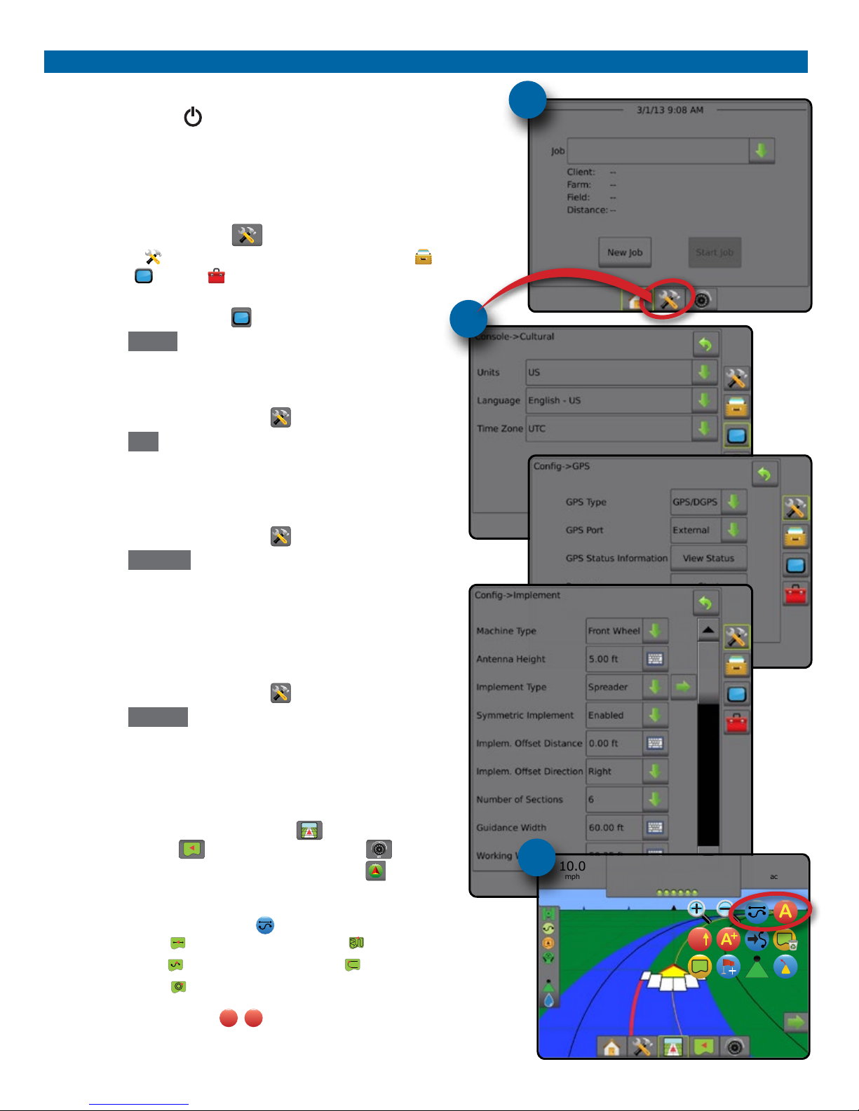
#1 Turn Power On
Press the POWER button to power on the console.
#2 Home Screen
Once the power up sequence has completed, the Home screen will appear with
the option to start a new job or continue an existing job.
#3 Go To Unit Setup
1. Press UNIT SETUP bottom tab .
The Conguration options will be displayed rst. Data Management ,
Console Setting and Tools can be accessed through the side tab keys.
Cultural Setup
2. Press CONSOLE side tab .
3. Press Cultural .
Culture is used to congure Units, Language and Time Zone settings.
GPS Setup
1. Press CONFIGURATION side tab .
2. Press GPS .
GPS is used to congure GPS Type, GPS Port and PRN as well as to
view GPS status information.
Implement Setup
1. Press CONFIGURATION side tab .
2. Press Implement .
Implement Setup is used to establish the various settings associated
with straight mode, spreader mode or staggered mode. Settings will
vary depending on if a SmartCable or Section Driver Module (SDM) is
present.
AutoSteer Setup
1. Press CONFIGURATION side tab .
2. Press AutoSteer .
When a Steering Control Module (SCM) is present, Assisted/Auto
Steering options will be available. For detailed setup instructions, refer
to your specic assisted/auto steering installation manual.
#4 Go To Guidance Screen
1. Press VEHICLE VIEW GUIDANCE tab , FIELD VIEW
GUIDANCE tab or REALVIEW GUIDANCE tab .
2. Press NAVIGATION AND GUIDANCE OPTIONS tab to display
navigation options.
Choose a Guidance Mode
►Straight AB
►Curved AB
►Circle Pivot
►Last Pass
►NextRow
Mark A and B Points
A
B
To establish a AB guideline.
#3
#2
10.0
mph
27.00
ac
> 0.0 <
A
AA
#4
i
98-05273-ENUS R4
HOME OVERVIEWSETUPIMPLEMENT FULL SCREENGPS INTRODUCTIONGUIDANCEDROPLET MONITOR
Table of Contents
CHAPTER 1 SYSTEM OVERVIEW 1
Product Upgrades Available.......................................................................................................................................................................1
SYSTEM COMPONENTS 1
Matrix Pro 570GS Console...........................................................................................................................................................................1
Matrix Pro 840GS Console...........................................................................................................................................................................2
RealView® Camera..........................................................................................................................................................................................2
Additional Information.................................................................................................................................................................................2
Power On..................................................................................................................................................................2
Power Off..................................................................................................................................................................2
Start Up Sequence....................................................................................................................................................2
Recommended Antenna Installation ..........................................................................................................................2
CONFIGURATIONS 3
CHAPTER 2 INTRODUCTION 4
BASIC SCREEN USE 4
Bottom Tab Keys .......................................................................................................................................................4
Unavailable Options When Job is Active....................................................................................................................4
Console Screen Colors..............................................................................................................................................5
Warnings and Information Pop-ups............................................................................................................................6
Setup Option Information...........................................................................................................................................6
Drop Down Menu Selections .....................................................................................................................................6
Scrolling Screens ......................................................................................................................................................6
Keyboard Entry Screen .............................................................................................................................................6
UNIT SETUP MODE MENU OPTIONS 7
CHAPTER 3 JOBS / HOME SCREEN 8
SIMPLE MODE 9
New Job .............................................................................................................................................................................................................9
Continue Job....................................................................................................................................................................................................9
Close Job............................................................................................................................................................................................................9
ADVANCED MODE 9
New Job .............................................................................................................................................................................................................9
Start Job.............................................................................................................................................................................................................9
Close Job............................................................................................................................................................................................................9
CHAPTER 4 FULL SCREEN VIDEO VIEW 10
CHAPTER 5 SYSTEM SETUP 11
OVERVIEW 11
Unavailable Options When Job is Active .......................................................................................................................12
CONFIGURATION 12
Implement...................................................................................................................................................................................................... 13
Implement Type .............................................................................................................................................................13
Single Section Setup ..............................................................................................................................................13
SmartCable or Section Driver Module Setup............................................................................................................14

ii www.teejet.com
HOMEOVERVIEW SETUP IMPLEMENTFULL SCREEN GPSINTRODUCTION GUIDANCE DROPLET MONITOR
Lightbar........................................................................................................................................................................................................... 15
AutoSteer........................................................................................................................................................................................................ 15
Assisted/Auto Steering Unavailable...............................................................................................................................16
Tilt Correction ............................................................................................................................................................................................... 16
Field Level Unavailable..................................................................................................................................................16
Tilt Correction Unavailable.............................................................................................................................................16
GPS.................................................................................................................................................................................................................... 17
PRN Not Shown.............................................................................................................................................................17
Video ................................................................................................................................................................................................................ 17
Video Setup Unavailable................................................................................................................................................17
Sensors ............................................................................................................................................................................................................ 18
Sensors Unavailable......................................................................................................................................................18
Pressure Sensor .....................................................................................................................................................18
Droplet Size Monitor .................................................................................................................................................................................. 19
Droplet Size Monitor Unavailable...................................................................................................................................19
DATA MANAGEMENT 20
Job Data .......................................................................................................................................................................................................... 20
Job Data Unavailable.....................................................................................................................................................20
Transfer ..................................................................................................................................................................21
Manage...................................................................................................................................................................21
Reports ............................................................................................................................................................................................................ 22
Options............................................................................................................................................................................................................ 22
Machine Settings......................................................................................................................................................................................... 23
Transfer ..................................................................................................................................................................24
Manage...................................................................................................................................................................24
Machine Settings Availability ...................................................................................................................................25
CONSOLE 26
Display............................................................................................................................................................................................................. 26
Cultural............................................................................................................................................................................................................ 27
Audio Volume ............................................................................................................................................................................................... 27
Demo Mode................................................................................................................................................................................................... 28
About ............................................................................................................................................................................................................... 28
TOOLS 29
CHAPTER 6 GUIDANCE 30
Navigation Screens Options.................................................................................................................................................................... 31
GUIDANCE BAR 32
Selectable Information.............................................................................................................................................32
Navigation Activity & Boom Status...........................................................................................................................32
STATUS BAR 33
Status/Information Screens ..................................................................................................................................................................... 33
NAVIGATION SCREENS 35
Vehicle View................................................................................................................................................................................................... 36
Field View........................................................................................................................................................................................................ 37
RealView Guidance ..................................................................................................................................................................................... 38
GUIDANCE MODES 39
iii
98-05273-ENUS R4
HOME OVERVIEWSETUPIMPLEMENT FULL SCREENGPS INTRODUCTIONGUIDANCEDROPLET MONITOR
Straight AB Guidance................................................................................................................................................................................. 39
Curved AB Guidance .................................................................................................................................................................................. 39
Circle Pivot Guidance ................................................................................................................................................................................. 39
Last Pass Guidance...................................................................................................................................................................................... 39
NextRow Guidance ..................................................................................................................................................................................... 39
No Guidance.................................................................................................................................................................................................. 39
GUIDELINES 40
Curved Lookahead Guideline ................................................................................................................................................................. 40
Marking A and B Points ............................................................................................................................................................................. 40
A+ Nudge Feature...................................................................................................................................................41
Next Guideline Feature.............................................................................................................................................................................. 42
Last Pass Guidelines.................................................................................................................................................................................... 42
NextRow Guidelines ................................................................................................................................................................................... 43
Azimuth Degree........................................................................................................................................................................................... 43
APPLICATION BOUNDARY 44
RETURN TO POINT 46
Marking a Return Point............................................................................................................................................46
Delete the Return Point ...........................................................................................................................................46
Guidance to a Return Point .....................................................................................................................................46
BOOMPILOT 47
Single Section ............................................................................................................................................................................................... 47
Console Only ..........................................................................................................................................................47
With Optional Speed/Sense Cable Switch ...............................................................................................................47
Using the Speed/Sense Cable Switch ...........................................................................................................................47
Using the Console..........................................................................................................................................................47
SmartCable or Section Driver Module ................................................................................................................................................. 48
Console Only ..........................................................................................................................................................48
Rate Controller or Switchbox...................................................................................................................................48
Rate Controller with Internal Section Driver Module......................................................................................................48
Speed/Sense Cable Switch ...........................................................................................................................................48
ZOOM IN/OUT 49
Vehicle View................................................................................................................................................................................................... 49
Field View........................................................................................................................................................................................................ 49
PAN MODE 49
REALVIEW SPECIFIC OPTIONS 50
RealView Setup Options............................................................................................................................................................................ 51
CHAPTER 7 GPS 52
GPS.................................................................................................................................................................................................................... 52
GPS Type................................................................................................................................................................53
GPS Port.................................................................................................................................................................53
External Receiver Minimum Conguration Requirements .............................................................................................53
GPS Status Information on Guidance Screens..............................................................................................................54
GGA Requirements........................................................................................................................................................54
Programming Receiver ...........................................................................................................................................55

iv www.teejet.com
HOMEOVERVIEW SETUP IMPLEMENTFULL SCREEN GPSINTRODUCTION GUIDANCE DROPLET MONITOR
Safety Information
TeeJet Technologies is not responsible for damage or physical harm caused by failure to adhere to the following safety
requirements.
As the operator of the vehicle, you are responsible for its safe operation.
The Matrix Pro GS in combination with any assisted/auto steering device is not designed to replace the vehicle’s operator.
Do not leave a vehicle while the Matrix Pro GS is engaged.
Be sure that the area around the vehicle is clear of people and obstacles before and during engagement.
The Matrix Pro GS is designed to support and improve efciency while working in the eld. The driver has full responsibility for the quality
and work related results.
Disengage or remove any assisted/auto steering device before operating on public roads.
PRN .......................................................................................................................................................................55
Alternate PRN ...............................................................................................................................................................55
PRN Not Shown.............................................................................................................................................................55
CHAPTER 8 IMPLEMENT SETUP 56
Implement Type........................................................................................................................................................................................... 56
BASIC SCREEN USE 57
SINGLE SECTION SETUP 58
Straight Implement Type..........................................................................................................................................59
TeeJet Spreader Implement Type ............................................................................................................................59
OEM Spreader Implement Type...............................................................................................................................60
SMARTCABLE OR SECTION DRIVER MODULE SETUP 61
Straight Implement Type..........................................................................................................................................62
TeeJet Spreader Implement Type ............................................................................................................................63
OEM Spreader Implement Type...............................................................................................................................64
Staggered Implement Type......................................................................................................................................65
IMPLEMENT OFFSET DISTANCE ADJUSTMENT 67
GPS Offset Adjustment Calculation .........................................................................................................................67
Implement Offset Adjustment...................................................................................................................................68
FACTORY SETTINGS & RANGES 69
Single Section ............................................................................................................................................................................................... 69
SmartCable or Section Driver Module ................................................................................................................................................. 69
CHAPTER 9 DROPLET SIZE MONITOR 71
DROPLET SIZE MONITOR SETUP 71
Pressure Sensor ............................................................................................................................................................................................ 71
Droplet Size Monitor .................................................................................................................................................................................. 72
Droplet Size Monitor Unavailable...................................................................................................................................72
Enable/Disable Droplet Size Monitor ......................................................................................................................72
Tip Preset ...............................................................................................................................................................73
Current Tip..............................................................................................................................................................73
DROPLET SIZE MONITOR OPERATION 74
Droplet Size Chart..........................................................................................................................................................74
Guidance Bar ..........................................................................................................................................................74

1
98-05273-ENUS R4
HOME OVERVIEWSETUPIMPLEMENT FULL SCREENGPS INTRODUCTIONGUIDANCEDROPLET MONITOR
CHAPTER 1 SYSTEM OVERVIEW
The Matrix Pro GS allows the management of multiple connected modules plus GPS mapping, Guidance, FieldPilot®, BoomPilot®and data
collection in a single console using CAN bus technology. This replaces multiple consoles in the cab with one robust system.
Product Upgrades Available
• FieldPilot®auto steering
• UniPilot®assisted steering
• BoomPilot®automated boom section control
• Tilt Gyro Module
• Video Selection Modules for up to 8 cameras
• External GPS receiver or antenna upgrades
• Fieldware® Link enhanced data organization application
• Pressure Sensor Interface Kit for Droplet Size Monitor
SYSTEM COMPONENTS
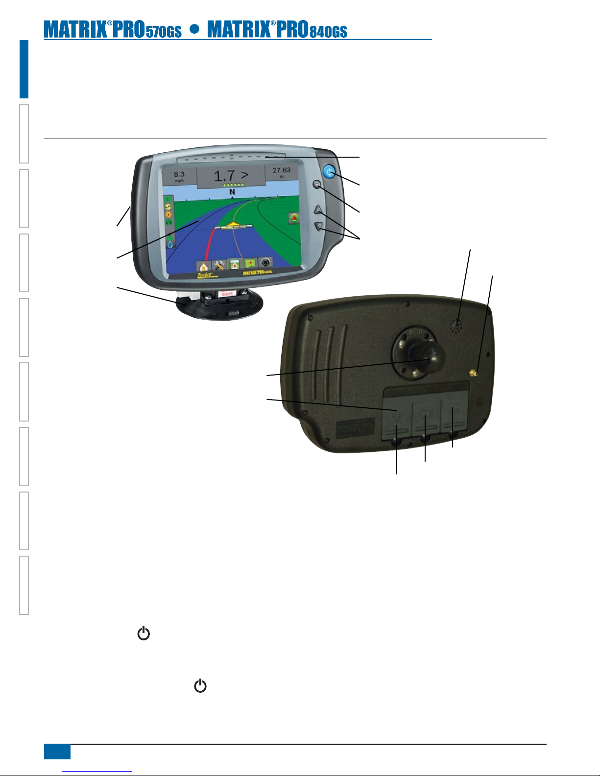
Matrix Pro 570GS Console
The Matrix Pro 570GS is designed to provide years of service under typical agricultural operating conditions. A tight tting enclosure,
combined with rubber covers for all connectors mean that typical dusty environments will not cause operational problems. While occasional
splashing of water will not damage the unit, the Matrix Pro 570GS is not designed for direct exposure to rain. Take care not to operate the
Matrix Pro GS in wet conditions.
Figure 1-1: Matrix Pro 570GS Console Front and Back
Power Button
USB Port with Rubber Cover
Rubber Connector Covers
GPS Antenna Connection
Integrated RAM Mount
(assembly required)
Speaker
Recessed Connectors
Speed Signal Connection
Camera Connection
Power Connection
Built In Lightbar
Power Button
USB Port with Rubber Cover
Standard RAM Bracket
(assembly required)
Bright Touch Screen
2www.teejet.com
HOMEOVERVIEW SETUP IMPLEMENTFULL SCREEN GPSINTRODUCTION GUIDANCE DROPLET MONITOR
Matrix Pro 840GS Console
The Matrix Pro 840GS is designed to provide years of service under typical agricultural operating conditions. A tight tting enclosure,
combined with rubber covers for all connectors mean that typical dusty environments will not cause operational problems. While occasional
splashing of water will not damage the unit, the Matrix Pro 840GS is not designed for direct exposure to rain. Take care not to operate the
Matrix Pro GS in wet conditions.
Figure 1-2: Matrix Pro 840GS Console Front and Back
Built In Lightbar
Power Button
USB Port
with Rubber Cover
Standard RAM Bracket
(assembly required)
Bright Touch Screen
Home Button
Zoom In/Out Buttons
Rubber Connector
Covers
GPS Antenna
Connection
Integrated RAM Mount
(assembly required)
Speaker
Speed Signal Connection
Camera Connection
Power Connection
RealView® Camera
The TeeJet Technologies RealView camera allows video images to be displayed on the Matrix Pro GS screen. The camera can be pointed
forward to enable RealView guidance over video, or it can be positioned to view other operational aspects of your equipment. The camera is
equipped with a exible RAM mount, integral sun shade and provides infrared illumination, allowing clear video images even in dark conditions.
Additional Information
All changes are saved automatically.
The console needs to be cycled off and back on when changing or
attaching equipment to the Matrix Pro GS system.
Power On
Press the POWER button to power on the console.
Upon power up, the Matrix Pro GS will begin its Start Up Sequence.
Power Off
Press and briey hold the POWER button until a conrmation
screen acknowledges shut down mode.
WARNING! Wait 30 seconds before restarting the console after
powering off.
Start Up Sequence
The console takes approximately 40 seconds to power up. During
this time a series of screens will be displayed, LEDs will power
on and off and brightness levels will uctuate. Once the power up
sequence has completed, the Home screen will appear.
Recommended Antenna Installation
The GPS antenna should be mounted as far forward as possible on
top of the cab on a metal surface of at least 10 cm square.

3
98-05273-ENUS R4
HOME OVERVIEWSETUPIMPLEMENT FULL SCREENGPS INTRODUCTIONGUIDANCEDROPLET MONITOR
CONFIGURATIONS
The following diagram is reective of typical Matrix Pro GS congurations. Due to the variety of possible congurations, this should be used
for reference purposes only.
Figure 1-3: Matrix Pro GS w/VSM & Multiple RealView Cameras, FieldPilot and BoomPilot
45-05626
Power/CAN/Data
Cable
(included with
FieldPilot, UniPilot
or BoomPilot kits)
10A Fuse
8 Pos.
to RS-232
BoomPilot
Section Driver
Module
(15 sections)
BoomPilot Harness
Part number
dependent on Rate Controller
Console Harness
Rate Controller
Remote ABSC
Status Switch
Connection
Valves
45-05381
Battery
3.66m
w/15Amp
Fuses
78-08075
Steering Control
Module (SCM)
45-07703
SCM Power In/Out
45-10103
Harness
Steering (A+B)
78-08072
Voltage
Regulator
45-07708
SCM Harness
32-04020
Optional
Footswitch
32-04040
Remote
Engage/
Disengage
Switch
91-07011
Steering
Wheel
Switch
Kit
45-08117
CAN Extension Cable 6m
Steering
Valve
16-00022
RealView Camera
Video Selector
Module
78-08067: 4 Channel
78-08068: 8 Channel
90-04005: 3 m
90-04006: 10 m
Droplet Size Monitor (DSM)
Pressure Interface Kit
45-05786: 6m
45-05787: 9m
Antenna Cable
78-50187
RXA-30
GPS Antenna 65-05226
Kit, Bracket
RXA-30 Antenna
45-05617: 6m
45-05618: 18m
Camera Extension Cable
5 Pos.
Matrix Pro 570GS
75-30082
75-30083 w/GLONASS
Matrix Pro 840GS
75-30084
75-30090 w/GLONASS
GPS Antenna
78-50155
78-50190 w/GLONASS
Kit, RAM Mount w/Suction Cup
90-02349 (Matrix 570)
90-02700 (Matrix 840)
Matrix
Assisted/Auto Steering
BoomPilot
Optional Accessory
4www.teejet.com
HOMEOVERVIEW SETUP IMPLEMENTFULL SCREEN GPSINTRODUCTION GUIDANCE DROPLET MONITOR
CHAPTER 2 INTRODUCTION
The Matrix Pro GS can be used as a simple current job system or advanced multi-job system. Regardless of which mode the console is in,
the basic screen functions are the same.
• Bottom Tabs and Side Tabs access the various screens and sub-screens
• Warnings and Information Pop-ups inform of console activities and details on setup or guidance functions
• Setup options can easily be set using the drop down menus or keyboard entry screens
To quickly nd a setup feature, see the Unit Setup Mode Menu Structure chart.
BASIC SCREEN USE
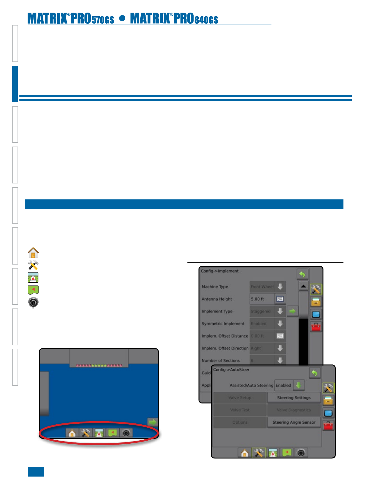
Bottom Tab Keys
The bottom tab keys are always available on screen. These keys give
access to jobs, setup options and navigation.
Home/Job Screen
Unit Setup
Vehicle View Guidance
Field View Guidance
RealView Guidance or
RealView Camera Full Screen Video View
NOTE: RealView Guidance options are only available with a camera
installed on the system.
Figure 2-1: Bottom Tab Keys
0.0
mph
0.00
ac > 0.0 <
Unavailable Options When Job is Active
When a job is active some setup options are unavailable. See the
Unit Setup Mode Menu Structure Chart for indication of which options
are not accessible.
Figure 2-2: Examples of Unavailable Options
5
98-05273-ENUS R4
HOME OVERVIEWSETUPIMPLEMENT FULL SCREENGPS INTRODUCTIONGUIDANCEDROPLET MONITOR
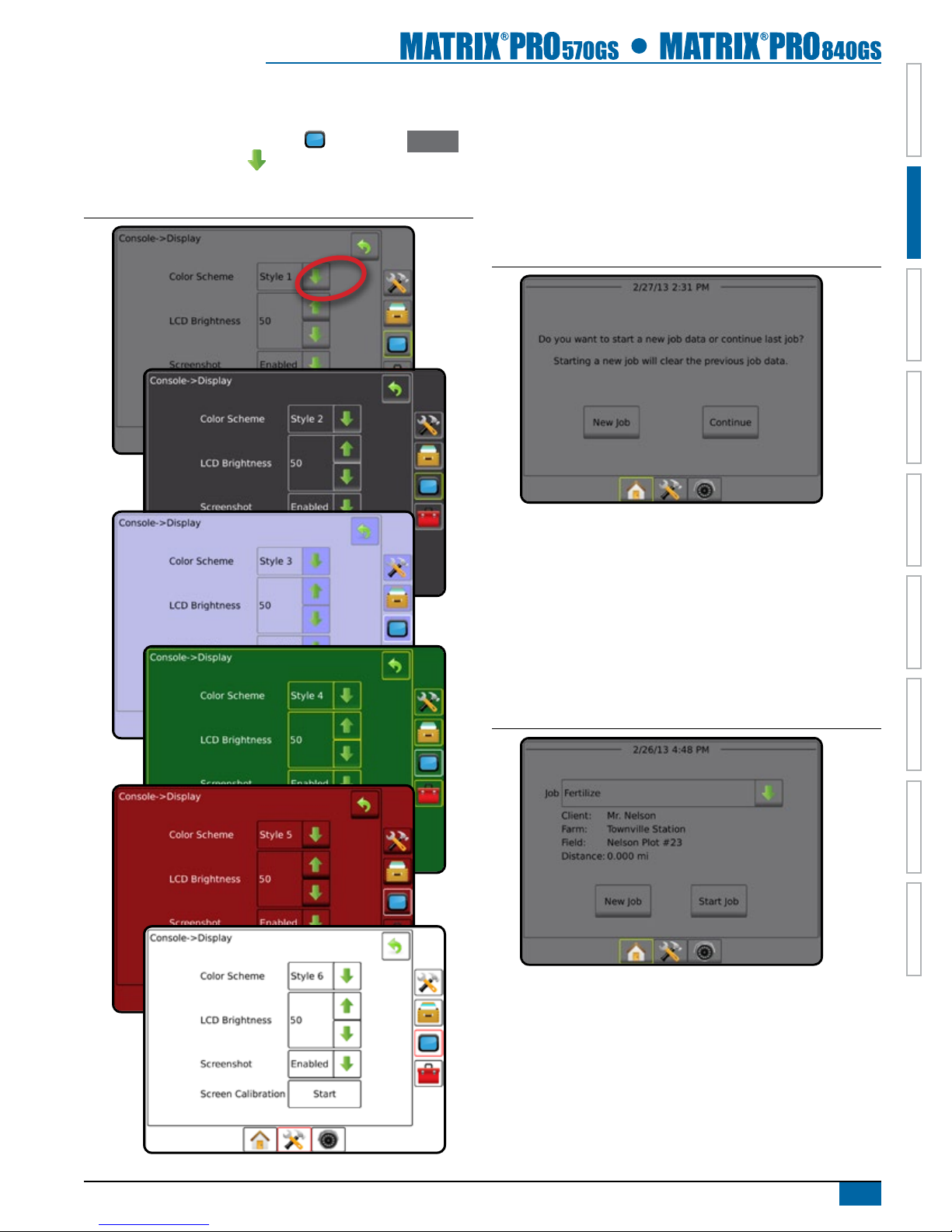
Console Screen Colors
The console is available in six color schemes. From the Unit Setup
Bottom Key, press CONSOLE side tab and enter the Display
options. Press DOWN arrow to access the Color Scheme
options to select color mode.
Figure 2-3: Color Schemes
Simple or Advanced Mode
To change between simple mode and advanced mode, see the
conguration chapter under Data Management – Options.
In simple mode, only one job will be available at a time. Only
bounded area and coverage areas are displayed on the home
screen. Only the current job is available for saving in Reports. Use
with Fieldware Link is not available.
Figure 2-4: Simple Mode Home Screen
In advanced mode, more than one job will be available at any time.
Client, farm, eld and job names; bounded and coverage areas;
and distance from selected job are displayed on the home screen.
Of the names, only the job name can be entered using the console.
All saved jobs can be made into a PDF, SHP or KML le in Data-
>Reports. With Fieldware Link, a user can input client, farm and
eld data as well as duplicate/edit jobs for reuse of boundaries and
guidelines. Client, Farm and Field information can only be inputted
using Fieldware Link.
Figure 2-5: Advanced Mode Home Screen

6www.teejet.com
HOMEOVERVIEW SETUP IMPLEMENTFULL SCREEN GPSINTRODUCTION GUIDANCE DROPLET MONITOR
Warnings and Information Pop-ups
A pop-up warning or information box will be displayed for
approximately ve (5) seconds. To remove the information box, tap
anywhere on the screen.
Setup Option Information
Press the option’s icon or option’s name of any menu item to display
a denition and range values of that item. To remove the information
box, press anywhere on the screen.
Figure 2-6: Example of Information Text Box
Drop Down Menu Selections
Press DOWN arrow to access the options. Use the UP/DOWN
arrows or slide bar if necessary to scroll through the extended
list. Select the appropriate option. To close the list without selecting an
option, tap anywhere on the screen outside the drop down menu.
Figure 2-7: Example of Drop Down Menu
Backward
Forward
Scrolling Screens
Some screens have more information or options that are visible
beyond the current screen. Use the UP/DOWN arrows or
slide bar to access additional options or information not currently
visible on the screen.
Figure 2-8: Example of Scrolling Screen
Keyboard Entry Screen
Press the KEYPAD icon . Use the numeric keypad to enter
a value.
Press the ACCEPT icon to save the settings or the
CANCEL icon to leave the keypad without saving.
Figure 2-9: Example of Keyboard
Antenna to Boom (ft)
1 2 3
14.50
Clear
4 5 6 <--
7 8 9
0 . +/-

7
98-05273-ENUS R4
HOME OVERVIEWSETUPIMPLEMENT FULL SCREENGPS INTRODUCTIONGUIDANCEDROPLET MONITOR
Conguration (page 12)
Implement
–
Machine Type
GPS Antenna Height
Implement Type
Symmetric Implement Layout
Implement Offset Distance
Implement Offset Direction
Number of Implement Sections
Guidance Width
Application/Working Width
Applied Area Alarm
–
Straight
Mode
Boom Offset Direction
Antenna to Boom Distance
Overlap
Delay On/Off Times
Spreader
Mode
Setup Type: TeeJet
• Antenna to Disks Distance
• Overlap
• Delay On/Off Times
• Spread Offset Distance
• Section Offsets
• Section Lengths
Setup Type: OEM
• Antenna to Disks Distance
• Start/Stop Distance
• Section Start/Stop Offsets
Staggered
Mode
Section 1 Offset Direction
Antenna to Section 1
Overlap
Delay On/Off Times
Section Offsets
AutoSteer
–Enabled/Disabled
–Valve
Setup
Valve Type
Valve Frequency
Minimum Duty Cycle Left/ Right
Maximum Duty Cycle
–Steering
Settings
Coarse Steering Adjustment
Fine Steering Adjustment
Deadband
Lookahead
–Valve Test
–Valve Diagnostics
–Options Steering Wheel Sensor
–
Steering
Angle
Sensor
Enable
Sensor Calibration
On Line Calibration
Tilt
Correction –Enabled/Disabled
Field Level
Lightbar –
LED Brightness
Display Mode
LED Spacing
GPS –
GPS Type
GPS Port
GPS Status Information
Program Receiver
PRN
Conguration (page 12)
Video –Cameras
Sensors –Pressure:
Maximum Pressure Rating
Low Pressure Alarm
High Pressure Alarm
Droplet Size
Monitor –Enabled/Disabled
Tip Selection
\
Data Management (page 20)
Job Data
–Transfer
Export
Import
Delete
– Manage
New
Copy
Delete
Reports –
Save PDF
Save KML
Save SHP
Save All Types
Options – Job Mode
Machine
Settings
–Transfer
Export
Import
Delete
– Manage
New
Copy
Delete
Save
Load
Console Settings (page 26)
Display –
User Interface Color Scheme
LCD Brightness
Screenshot
Screen Calibrate
Cultural –
Units
Language
Time Zone
Audio
Volume –Audio Volume
Demo Mode – Start
About –
System Information
QR Code - direct link to User Manual
Save System Info
Tools (page 29)
Extras –Calculator
Units Converter
Available during an active job
Not Available during an active job
UNIT SETUP MODE MENU OPTIONS
8www.teejet.com
HOMEOVERVIEW SETUP IMPLEMENTFULL SCREEN GPSINTRODUCTION GUIDANCE DROPLET MONITOR
CHAPTER 3 JOBS / HOME SCREEN
Once the power up sequence has completed, the Home screen will appear with the option to start a new job or continue an existing job.
The console must have GPS before starting or continuing a job.
Setup for the specic machine and its components must be completed before starting a job. Once a job is
active, some setup options are not available to be changed. See the Unit Setup Mode Menu Structure chart in the introduction chapter for
details.
To change between simple mode and advanced mode, see the conguration chapter under Data Management –>Options.
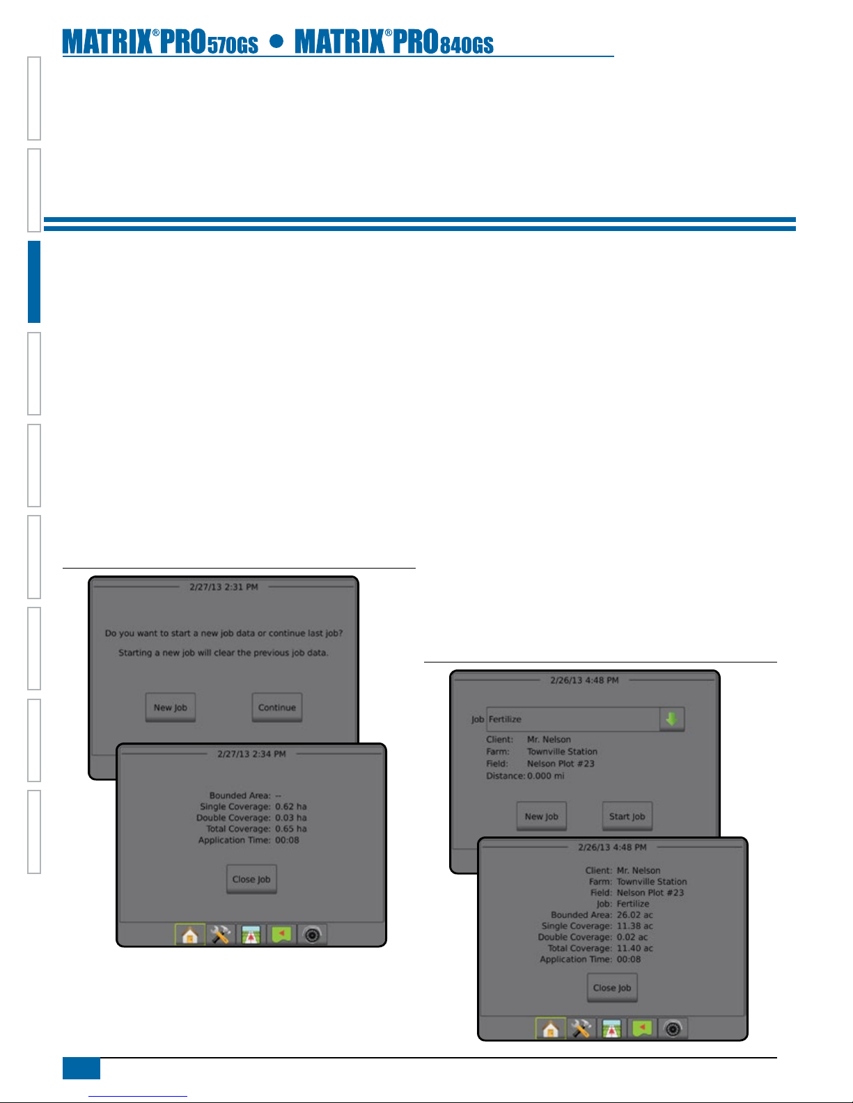
Simple Mode
In simple mode, only one job will be available at a time. Only bounded
area, coverage areas and application time are displayed on the home
screen. Only the current job is available for saving in Reports. Use
with Fieldware Link is not available.
Figure 3-1: Simple Mode Home Screen
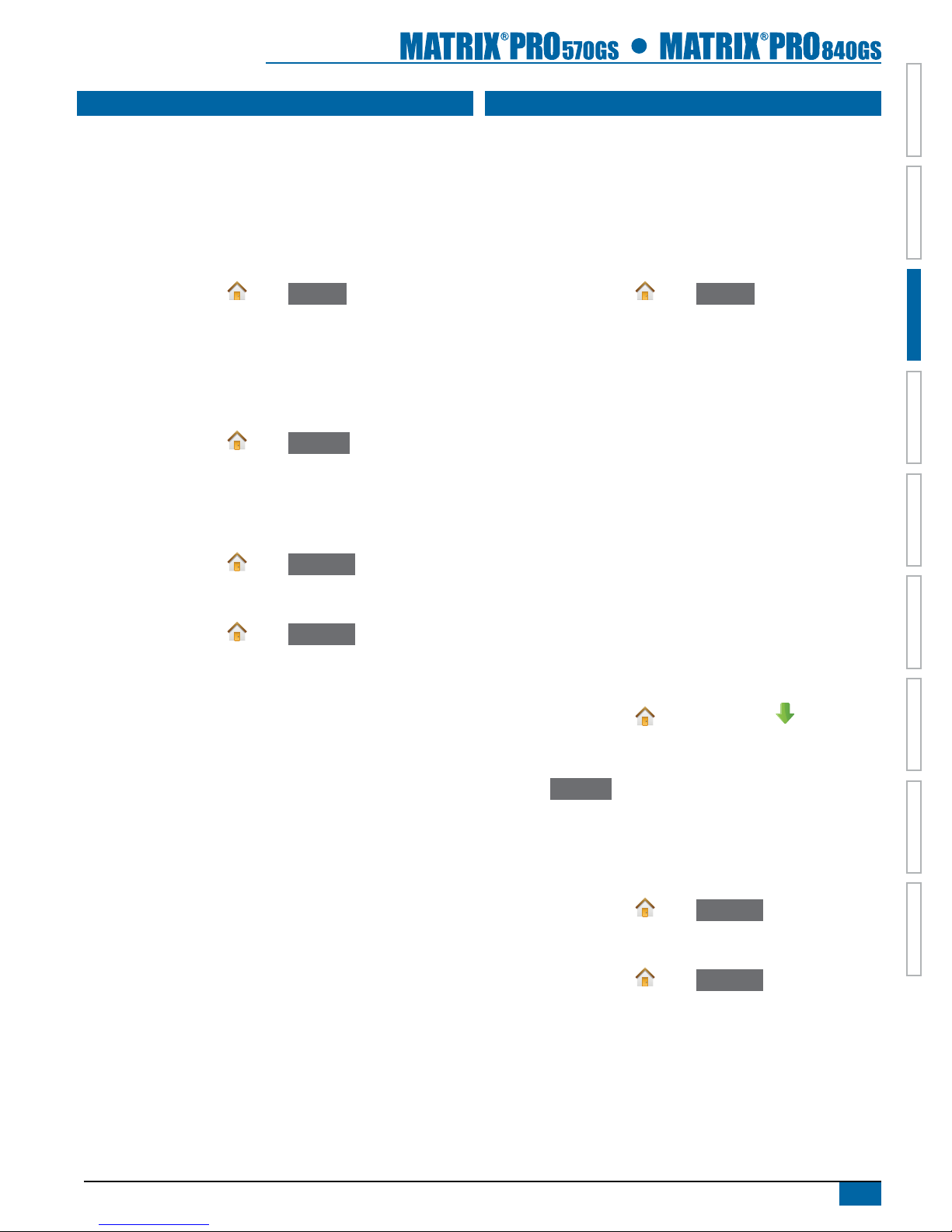
Advanced Mode
In advanced mode, more than one job will be available at any time.
Client, farm, eld and job names; bounded and coverage areas;
application time; and distance from selected job are displayed on the
home screen. Of the names, only the job name can be entered using
the console. All saved jobs can be made into a PDF, SHP or KML le
in Data->Reports. With Fieldware Link, a user can input client, farm
and eld data as well as duplicate/edit jobs for reuse of boundaries
and guidelines. Client, Farm and Field information can only be inputted
using Fieldware Link.
Figure 3-2: Advanced Mode Home Screen
9
98-05273-ENUS R4
HOME OVERVIEWSETUPIMPLEMENT FULL SCREENGPS INTRODUCTIONGUIDANCEDROPLET MONITOR
SIMPLE MODE
Once the power up sequence has completed, the Home screen will
appear with the option to start a new job or continue an existing job.
The console must have GPS before starting or continuing a job.
New Job
Starting a new job will clear the previous job data.
To start a New Job:
1. On the Home screen , press New Job .
The console will jump to Vehicle View.
Continue Job
The Continue button is not available when the current job is more
than two (2) UTM Zones away.
To continue the existing job:
1. On the Home screen , press Continue .
The console will jump to Vehicle View and begin providing navigation
information.
Close Job
To close a job:
1. On the Home screen , press Close Job .
To create a report of the job when closing a job:
1. Insert a USB drive into the USB port of the console.
2. On the Home screen , press Close Job .
3. Select:
►Yes – to create a report of the last job
►No – to return to the Home screen without saving
ADVANCED MODE
Once the power up sequence has completed, the Home screen will
appear with the option to start a new job or continue an existing job.
The console must have GPS before starting or continuing a job.
New Job
Starting a new job will clear the previous job data.
To start a New Job:
1. On the Home screen , press New Job .
2. Press:
►Yes – to automatically generate a name
►No – to enter a name using the on screen keyboard
Client, farm and eld information are inputted using Fieldware Link.
The console will jump to Vehicle View.
Start Job
The Matrix Pro is programd with a eld nder tool to assist the
user in nding the job closest to the vehicle’s location. With GPS
acquired, the job pick list will be updated every ten seconds. During
this update, the list of jobs is sorted by distance and the closest two
jobs are displayed on the top of the list. The remaining jobs are listed
beneath these.
The Start Job button is not available and the Distance will show “Out
of Range” when the current job is more than two (2) UTM Zones
away. The Distance will show “No Data” when the current job has no
recorded information.
To continue the existing job:
1. On the Home screen , press DOWN arrow to access the
list of jobs saved in the console.
2. Select the job name to be started/continued.
3. Press Start Job .
The console will jump to Vehicle View and begin providing navigation
information.
Close Job
To close a job:
1. On the Home screen , press Close Job .
To create a report of the job when closing a job:
1. Insert a USB drive into the USB port of the console.
2. On the Home screen , press Close Job .
3. Select:
►Yes – to create a report of the last job
►No – to return to the Home screen without saving

10 www.teejet.com
HOMEOVERVIEW SETUP IMPLEMENTFULL SCREEN GPSINTRODUCTION GUIDANCE DROPLET MONITOR
CHAPTER 4 FULL SCREEN VIDEO VIEW
RealView Full Screen Video View allows live video input to be displayed. View video feed(s) and setup cameras without GPS available.
Options for RealView Guidance are not available on this screen.
If a Video Selection Module (VSM) is installed on the system, two (2) video options are available:
►Single Camera View – one (1) of up to eight (8) camera inputs can be selected to change the view of the video input.
►Split Camera View – one (1) of two (2) sets of four (4) camera inputs (A/B/C/D or E/F/G/H) can be selected to divide the screen
into four separate video feeds.
Also available is:
►RealView Camera Snapshot – saves a still photo of the current view on the screen to a USB drive
1. Press REALVIEW CAMERA FULL SCREEN VIDEO VIEW bottom tab .
Figure 4-1: RealView Camera Full Screen Video View
11
98-05273-ENUS R4
HOME OVERVIEWSETUPIMPLEMENT FULL SCREENGPS INTRODUCTIONGUIDANCEDROPLET MONITOR
CHAPTER 5 SYSTEM SETUP
System Setup is used to congure the console, the machine and its implements. Four side tabs access options for Machine/Implement
Conguration, Data Management, Console Settings and Tools.
OVERVIEW
Four side tabs access setup options for:
Machine/Implement Conguration
• Implement (Straight, Spreader, Staggered)
• Lightbar
• Auto Steer (Valve Setup, Steering Settings, Valve Test, Valve
Diagnostics, Steering Wheel Sensor, Steering Angle Sensor)
• Tilt Correction
• GPS
• Video Conguration
• Sensors (Pressure Monitor)
• Droplet Size Monitor
Data Management
• Job Data (Transfer, Manage)
• Reports
• Options: Job Mode
• Machine Settings (Transfer, Manage)
Console Settings
• Display
• Cultural
• Audio Volume
• Demo Mode
• About System Information
Tools (Calculator, Units Converter)
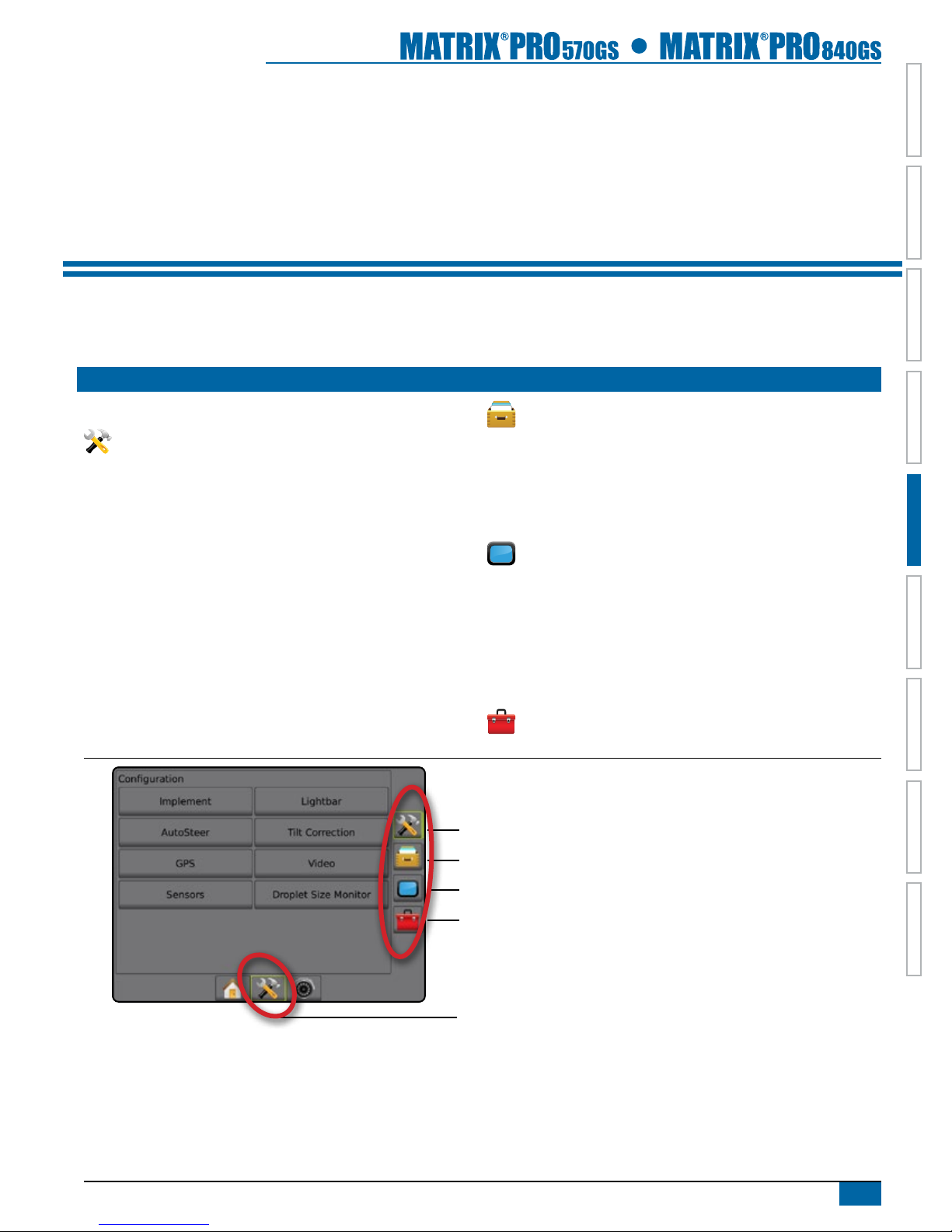
Figure 5-1: Setup Options
Conguration side tab
Data Management side tab
Console Settings side tab
Tools side tab
Unit Setup bottom tab
Side Tabs

12 www.teejet.com
HOMEOVERVIEW SETUP IMPLEMENTFULL SCREEN GPSINTRODUCTION GUIDANCE DROPLET MONITOR
Unavailable Options When Job is Active
When a job is active some setup options are unavailable. See the Unit Setup Mode Menu Structure Chart for indication of which options are
not accessible.
Figure 5-2: Examples of Unavailable Options
CONFIGURATION
Conguration is used to congure the Implement, Lightbar, AutoSteer, Tilt Correction, GPS, Video, Sensors and Droplet Size Monitor.
NOTE: Feature availability will vary depending on the devices available on the Matrix Pro GS system.
1. Press UNIT SETUP bottom tab .
2. Press CONFIGURATION side tab .
3. Select from:
►Implement – used to establish machine type, GPS antenna
height, implement type, symmetric implement layout,
implement offset distance/direction, number of implement
sections, guidance width, application/working width and
applied area alarm times.
● In Straight Mode – boom offset direction, antenna to boom
distance, overlap percentage, implement delay on time and
implement delay off time
● In Spreader Mode: TeeJet – antenna to disks distance,
overlap percentage, implement delay on time, implement
delay off time, spread offset distance, section offset
distances and section lengths
● In Spreader Mode: OEM – antenna to disks distance, start
distance, stop distance, section start offsets and section stop
offsets
● In Staggered Mode – section 1 offset direction, antenna to
section 1 distance, overlap percentage, implement delay on
time, implement delay off time and section offsets
►Lightbar – used to establish LED brightness, display mode and
LED spacing
►AutoSteer – used to enable/disable assisted/auto steering as
well as establish valve setup settings, steering settings and
steering angle sensor settings; and perform valve tests, or
valve diagnostics
►Tilt Correction – used to enable/disable and calibrate the tilt
gyro module, allowing for tilt correction for application on hilly
or sloped terrain
►GPS – used to establish the GPS type, port and PRN as well
as to view GPS status information
►Video – used to set up individual cameras
►Sensor – used to establish pressure sensor settings
►Droplet Size Monitor – used to enable/disable and set up
preset and current tips
Figure 5-3: Configuration Options
13
98-05273-ENUS R4
HOME OVERVIEWSETUPIMPLEMENT FULL SCREENGPS INTRODUCTIONGUIDANCEDROPLET MONITOR
Implement
Implement Setup is used to establish the various settings associated
with straight mode, spreader mode or staggered mode. For detailed
setup instructions, refer to the Implement chapter in this manual.
Settings will vary depending on if a SmartCable or Section Driver
Module (SDM) is present.
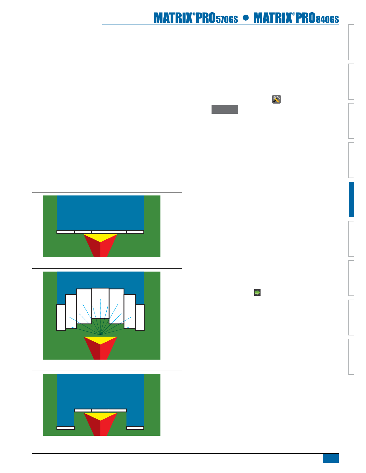
Implement Type
Implement type selects the type of application pattern that most
closely represents your system.
● In Straight Mode – the boom sections have no length and are
on a line a xed distance from antenna
● In Spreader Mode – a virtual line is created in line with the
delivery disks from which the application section or sections can
vary in length and can be at different distances from the line
● In Staggered Mode – a virtual line is created in line with
Section 1 from which the application section or sections have
no length and can be at different distances from antenna
Figure 5-4: Implement Type - Straight
Figure 5-5: Implement Type - Spreader
Figure 5-6: Implement Type - Staggered
Single Section Setup
Single Section Setup is used when a SmartCable or Section Driver
Module (SDM) is not on the system. The entire boom or delivery
area is considered to be one section.
NOTE: If a SmartCable or Section Driver Module (SDM) is present,
refer to "SmartCable or Section Driver Module Setup" to view
setup steps.
1. Press CONFIGURATION side tab .
2. Press Implement .
3. Select from:
►Machine Type – used to select the type of machine that most
closely represents your machine.
►GPS Antenna Height – used to measure the height of the
antenna from the ground
►Implement Type – used to select the layout of the sections for
the applied product location.
►Implement Offset Distance – used to enter the distance from
the centerline of the machine to the center of the implement
►Implement Offset Direction – used to enter the direction from
the centerline of the machine to the center of the implement
while facing in the machine's forward direction
►Guidance Width – used to enter the distance between the
guidelines
►Application Width [Straight Implement Type] – used to enter
the total width of the implement
►Working Width [Spreader Implement Type] – used to enter the
total width of the implement
►Applied Area Alarm – used to establish an alert to signal when
exiting or entering an applied area
4. Press NEXT PAGE arrow to set up the selected specic
implement type's options.

14 www.teejet.com
HOMEOVERVIEW SETUP IMPLEMENTFULL SCREEN GPSINTRODUCTION GUIDANCE DROPLET MONITOR
Figure 5-7: Implement
SmartCable or Section Driver Module Setup
SmartCable or Section Driver Module Setup is used when a
SmartCable or Section Driver Module (SDM) is on the system. The
boom or delivery area can be entered as up to 15 sections. Each
section can vary in width and in spreader mode, can vary in length.
Additional options available with a SDM include Application Overlap,
Application Delay and Staggered Mode.
NOTE: If a SmartCable or Section Driver Module (SDM) is not
present, refer to "Single Section Setup" to view setup steps.
1. Press CONFIGURATION side tab .
2. Press Implement .
3. Select from:
►Machine Type – used to select the type of machine that most
closely represents your machine.
►GPS Antenna Height – used to measure the height of the
antenna from the ground
►Implement Type – used to select the layout of the sections for
the applied product location.
►Symmetric Implement Layout – used to establish if sections
are paired and therefore share the same width, offset and
length values
►Implement Offset Distance – used to enter the distance from
the centerline of the machine to the center of the implement
►Implement Offset Direction – used to enter the direction from
the centerline of the machine to the center of the implement
while facing in the machine's forward direction
►Number of Implement Sections – used to select the number of
implement sections
►Guidance Width – used to enter the distance between the
guidelines
►Application Width [Straight Boom Type or Staggered Boom
Type] – used to enter the total width of all sections of the
implement
►Working Width [Spreader Boom Type] – used to enter the total
width of all sections of the implement
4. Press NEXT PAGE arrow to set up the selected specic
implement type's options.
Figure 5-8: Implement
This manual suits for next models
1
Table of contents
Other TeeJet GPS manuals


 user manual")


