TeeJet Matrix Pro 570GS User manual

VOYAGER®570G
USER MANUAL
USER MANUAL
MATRIX PRO GS
Software version 4.31
GETTING STARTED
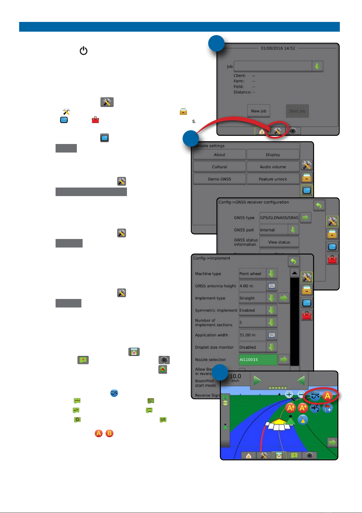
#1 Turn power on
Press the POWER button to power on the console.
#2 Home screen
Once the power up sequence has completed, the Home screen will appear
with the option to start a new job or continue an existing job.
#3 Go to Unit setup
1. Press UNIT SETUP bottom tab .
The Conguration options will be displayed rst. Data management ,
Console settings and Tools can be accessed through the side tab keys.
Cultural setup
1. Press CONSOLE side tab .
2. Press Cultural .
Culture is used to congure units, language and time zone settings.
GNSS setup
1. Press CONFIGURATION side tab .
2. Press GNSS Receiver Conguration .
GNSS is used to congure GNSS type, GNSS port and PRN as well
as to view GNSS status information.
Implement setup
1. Press CONFIGURATION side tab .
2. Press Implement .
Implement setup is used to establish the various settings associated
with straight mode, spreader mode or staggered mode. Settings will
vary depending on if an AutoSteer or BoomPilot system is present.
AutoSteer setup
1. Press CONFIGURATION side tab .
2. Press AutoSteer .
When a Steering Control Module (SCM or SCM Pro) is present,
assisted/auto steering options will be available. For detailed setup
instructions, refer to your specic AutoSteer installation manual.
#4 Go to Guidance screen
1. Press VEHICLE VIEW GUIDANCE tab , FIELD VIEW
GUIDANCE tab or REALVIEW GUIDANCE tab .
2. Press NAVIGATION AND GUIDANCE OPTIONS tab to
display navigation options.
Choose a guidance mode
►Straight AB
►Curved AB
►Circle Pivot
►Last Pass
►NextRow
►Adaptive Curve
Mark A and B points
To establish a AB guideline.
#3
#2
10.0
km/h
27.00
ha
0.0
#4

i
98-05273-EN R7
MATRIX®Pro 570GS •MATRIX®Pro840GS
HOMESETUPGUIDANCE FULL SCREENIMPLEMENT INTRODUCTIONGNSSRATE CONTROLAPPENDIX
Table of contents
CHAPTER 1 INTRODUCTION 1
Product upgrades available........................................................................................................................................................................1
SYSTEM COMPONENTS 1
Matrix Pro 570GS console............................................................................................................................................................................1
Matrix Pro 840GS console............................................................................................................................................................................2
Buttons...............................................................................................................................................................................................................2
Additional information.................................................................................................................................................................................2
RealView® camera...........................................................................................................................................................................................3
CONFIGURATIONS 3
BASIC SCREEN USE 3
Bottom tab keys ........................................................................................................................................................3
Unavailable options when job is active ......................................................................................................................3
Console screen colours.............................................................................................................................................4
Simple or advanced mode.........................................................................................................................................4
Warnings and information pop-ups ............................................................................................................................5
Setup option information ...........................................................................................................................................5
Drop-down menu selections ......................................................................................................................................5
Scrolling screens.......................................................................................................................................................5
Keyboard entry screen ..............................................................................................................................................6
Next page .................................................................................................................................................................6
Checkboxes ..............................................................................................................................................................6
CHAPTER 2 JOBS / HOME SCREEN 7
Simple mode .............................................................................................................................................................7
Advanced mode ........................................................................................................................................................7
SIMPLE MODE 8
New job..............................................................................................................................................................................................................8
Continue job.....................................................................................................................................................................................................8
Close job ............................................................................................................................................................................................................8
ADVANCED MODE 8
New job..............................................................................................................................................................................................................8
Start job..............................................................................................................................................................................................................8
Distance ..........................................................................................................................................................................8
Close job ............................................................................................................................................................................................................8
CHAPTER 3 FULL SCREEN VIDEO VIEW 9
Camera snapshot......................................................................................................................................................................................... 10
VSM camera options................................................................................................................................................................................... 10
CHAPTER 4 SYSTEM SETUP 11
OVERVIEW 11
ii www.teejet.com
MATRIX®Pro 570GS •MATRIX®Pro 840GS
HOME SETUP GUIDANCEFULL SCREEN IMPLEMENTINTRODUCTION GNSS RATE CONTROL APPENDIX
CONFIGURATION 12
Implement...................................................................................................................................................................................................... 13
Implement type ..............................................................................................................................................................13
Single section setup ...............................................................................................................................................13
Multiple sections with SDM/SFM setup....................................................................................................................14
Droplet size monitor ................................................................................................................................................15
Nozzle selection......................................................................................................................................................15
Reverse sense options............................................................................................................................................16
Mapping and guidance [Lightbar] ........................................................................................................................................................ 16
Mapping and guidance [console only]......................................................................................................................16
Mapping and guidance using an external lightbar ....................................................................................................17
User entered mapping location................................................................................................................................18
GNSS receiver conguration.................................................................................................................................................................... 19
PRN not shown..............................................................................................................................................................19
Video ................................................................................................................................................................................................................ 19
Video setup unavailable.................................................................................................................................................19
Sensors ............................................................................................................................................................................................................ 20
Sensors unavailable.......................................................................................................................................................20
Input/output module pressure sensor.......................................................................................................................20
Droplet size monitor ......................................................................................................................................................20
Product............................................................................................................................................................................................................ 21
Third-party rate control............................................................................................................................................................................. 21
AutoSteer........................................................................................................................................................................................................ 22
Assisted/Auto steering unavailable................................................................................................................................22
FieldPilot [using a SCM]..........................................................................................................................................22
FieldPilot Pro / UniPilot Pro [using a SCM Pro]........................................................................................................22
Active vehicle.................................................................................................................................................................23
Tilt correction................................................................................................................................................................................................ 24
Field level unavailable....................................................................................................................................................24
Tilt correction unavailable ..............................................................................................................................................24
DATA MANAGEMENT 24
Job data........................................................................................................................................................................................................... 24
Job data unavailable......................................................................................................................................................25
Transfer ..................................................................................................................................................................25
Manage...................................................................................................................................................................26
Reports ............................................................................................................................................................................................................ 27
Options (Job mode).................................................................................................................................................................................... 27
Machine settings.......................................................................................................................................................................................... 28
Transfer ..................................................................................................................................................................29
Manage...................................................................................................................................................................29
Copy machine prole .....................................................................................................................................................30
CONSOLE 30
About ............................................................................................................................................................................................................... 31
Display............................................................................................................................................................................................................. 31
Cultural............................................................................................................................................................................................................ 32
Audio volume................................................................................................................................................................................................ 32
Demo GNSS ................................................................................................................................................................................................... 33
Restart Demo GNSS ...............................................................................................................................................33
Feature unlock.............................................................................................................................................................................................. 33

iii
98-05273-EN R7
MATRIX®Pro 570GS •MATRIX®Pro840GS
HOMESETUPGUIDANCE FULL SCREENIMPLEMENT INTRODUCTIONGNSSRATE CONTROLAPPENDIX
TOOLS 34
Upload software........................................................................................................................................................................................... 34
Extras................................................................................................................................................................................................................ 35
CHAPTER 5 GNSS RECEIVER CONFIGURATION 36
GNSS receiver conguration.................................................................................................................................................................... 36
GNSS type..............................................................................................................................................................36
GNSS port...............................................................................................................................................................37
External receiver minimum conguration requirements.................................................................................................37
GNSS status information.........................................................................................................................................38
GNSS status information on guidance screens .............................................................................................................38
GGA Requirements........................................................................................................................................................38
Programme .............................................................................................................................................................39
PRN .......................................................................................................................................................................39
Alternate PRN ...............................................................................................................................................................39
PRN not shown..............................................................................................................................................................39
Show refresh GNSS position button ........................................................................................................................40
GNSS glossary ............................................................................................................................................................................................... 40
CHAPTER 6 IMPLEMENT SETUP 42
IMPLEMENT TYPE 42
Section numbers .....................................................................................................................................................42
Straight............................................................................................................................................................................................................ 43
Single section .........................................................................................................................................................43
Multiple sections .....................................................................................................................................................43
Spreader – TeeJet......................................................................................................................................................................................... 44
Single section .........................................................................................................................................................44
Multiple sections .....................................................................................................................................................45
Spreader – OEM............................................................................................................................................................................................ 47
Single section .........................................................................................................................................................47
Multiple sections .....................................................................................................................................................47
Staggered....................................................................................................................................................................................................... 48
Multiple sections .....................................................................................................................................................48
APPLICATION OR WORKING WIDTH 50
Single section .........................................................................................................................................................50
Multiple sections .....................................................................................................................................................50
IMPLEMENT LATERAL OFFSET DISTANCE ADJUSTMENT 51
GNSS offset adjustment calculation.........................................................................................................................51
Implement lateral offset adjustment.........................................................................................................................52
REVERSE SENSE 53
Reverse on guidance screens .................................................................................................................................53
NOZZLE SELECTION 54
Preset .....................................................................................................................................................................54
Current nozzle.........................................................................................................................................................55
iv www.teejet.com
MATRIX®Pro 570GS •MATRIX®Pro 840GS
HOME SETUP GUIDANCEFULL SCREEN IMPLEMENTINTRODUCTION GNSS RATE CONTROL APPENDIX
DROPLET SIZE MONITOR 55
Setup................................................................................................................................................................................................................ 55
Enable/disable DSM................................................................................................................................................55
Nozzle selection / current nozzle.............................................................................................................................56
Input/output module pressure sensor.......................................................................................................................56
Operation ....................................................................................................................................................................................................... 56
Status bar ...............................................................................................................................................................56
Droplet size chart...........................................................................................................................................................56
Guidance bar ..........................................................................................................................................................56
BOOMPILOT SECTION CONTROL 57
CHAPTER 7 GUIDANCE AND MAPPING 58
Overview......................................................................................................................................................................................................... 58
Screens options............................................................................................................................................................................................ 59
GUIDANCE BAR 63
Navigation activity & boom status............................................................................................................................63
Cross track error ............................................................................................................................................................63
Selectable information.............................................................................................................................................63
STATUS BAR 64
Status/Information Screens ..................................................................................................................................................................... 64
NAVIGATION SCREENS 66
Vehicleview................................................................................................................................................................................................... 66
Field View........................................................................................................................................................................................................ 67
RealView guidance...................................................................................................................................................................................... 68
GUIDANCE MODES 69
Straight AB guidance.................................................................................................................................................................................. 69
Curved AB guidance................................................................................................................................................................................... 69
Adaptive curve AB guidance................................................................................................................................................................... 69
Circle pivot guidance ................................................................................................................................................................................. 69
Last pass guidance...................................................................................................................................................................................... 69
NextRow guidance...................................................................................................................................................................................... 70
No guidance .................................................................................................................................................................................................. 70
GUIDELINES 70
Marking A and B points............................................................................................................................................................................. 70
A+ nudge feature ....................................................................................................................................................71
Next guideline feature............................................................................................................................................................................... 72
Last pass guidelines.................................................................................................................................................................................... 72
NextRow guidelines.................................................................................................................................................................................... 73
Azimuth degree ........................................................................................................................................................................................... 73
RETURN TO POINT 74
Marking a return point .............................................................................................................................................74
Delete the return point.............................................................................................................................................74
Guidance to a return point.......................................................................................................................................74

v
98-05273-EN R7
MATRIX®Pro 570GS •MATRIX®Pro840GS
HOMESETUPGUIDANCE FULL SCREENIMPLEMENT INTRODUCTIONGNSSRATE CONTROLAPPENDIX
BOOMPILOT 75
No section control module ...................................................................................................................................................................... 75
Console only ...........................................................................................................................................................75
With optional work on/off switch ..............................................................................................................................75
Using the console ..........................................................................................................................................................75
With TeeJet section control module and switchbox or ISM......................................................................................................... 75
With TeeJet section control module ..................................................................................................................................................... 76
CURVED LOOKAHEAD 76
REFRESH GNSS POSITION 76
BOUNDARIES AND POLYGONS 77
Mapping location............................................................................................................................................................77
Boundaries..................................................................................................................................................................................................... 77
Delete last marked boundary...................................................................................................................................79
Boundary on status bar ...........................................................................................................................................79
Polygons ......................................................................................................................................................................................................... 79
Delete last marked polygon .....................................................................................................................................80
MAPPING OPTIONS 81
Polygon mapping........................................................................................................................................................................................ 81
Rate control mapping................................................................................................................................................................................ 81
ZOOM IN/OUT 82
Vehicleview................................................................................................................................................................................................... 82
Fieldview........................................................................................................................................................................................................ 82
PAN MODE 82
REALVIEW SPECIFIC OPTIONS 83
RealView guidance options ..................................................................................................................................................................... 83
Camera snapshot......................................................................................................................................................................................... 84
VSM camera options................................................................................................................................................................................... 84
CHAPTER 8 THIRDPARTY RATE CONTROL 85
THIRDPARTY RATE CONTROL UNLOCK 85
SETUP OPTIONS 86
Third-party rate control............................................................................................................................................86
Product ...................................................................................................................................................................86
GUIDANCE SCREEN OPTIONS 87
Guidance bar ..........................................................................................................................................................87
Status bar ...............................................................................................................................................................87

vi www.teejet.com
MATRIX®Pro 570GS •MATRIX®Pro 840GS
HOME SETUP GUIDANCEFULL SCREEN IMPLEMENTINTRODUCTION GNSS RATE CONTROL APPENDIX
MAPPING OPTIONS 88
Duplicating and transferring maps .................................................................................................................................88
Coverage map............................................................................................................................................................................................... 88
On screen mapping........................................................................................................................................................88
Polygons map ............................................................................................................................................................................................... 89
On screen mapping........................................................................................................................................................89
Prescription map.......................................................................................................................................................................................... 89
On screen mapping........................................................................................................................................................89
Application and target rate maps.......................................................................................................................................................... 89
Application map ......................................................................................................................................................89
On screen mapping........................................................................................................................................................89
Target rate map.......................................................................................................................................................90
On screen mapping........................................................................................................................................................90
Target rates ....................................................................................................................................................................90
APPENDIX A SYSTEM CONFIGURATIONS 91
APPENDIX B MATRIXPROGS CONSOLE MENU SETTINGS 93
APPENDIX C UNIT SPECIFICATIONS 97
APPENDIX D SETTING RANGES 98
APPENDIX E UTM COORDINATES AND ZONES 98

1
98-05273-EN R7
MATRIX®Pro 570GS •MATRIX®Pro840GS
HOMESETUPGUIDANCE FULL SCREENIMPLEMENT GNSSRATE CONTROLAPPENDIX INTRODUCTION
CHAPTER 1 INTRODUCTION
The Matrix Pro GS allows the management of multiple connected modules plus GNSS mapping, Guidance, FieldPilot®, BoomPilot®,
Rate Control, and data collection in a single console using CAN bus technology. This replaces multiple consoles in the cab with one
robust system.
Product upgrades available
• FieldPilot®or FieldPilot®Pro auto steering
• UniPilot®or UniPilot®Pro assisted steering
• BoomPilot®automated boom section control
• Tilt Gyro Module
• Video Selection Modules for up to 8 cameras
• External GNSS receiver or antenna upgrades
• Fieldware®Link enhanced data organisation application
• Pressure Sensor Interface Kit for Droplet Size Monitor
• Third Party Rate Control
SYSTEM COMPONENTS
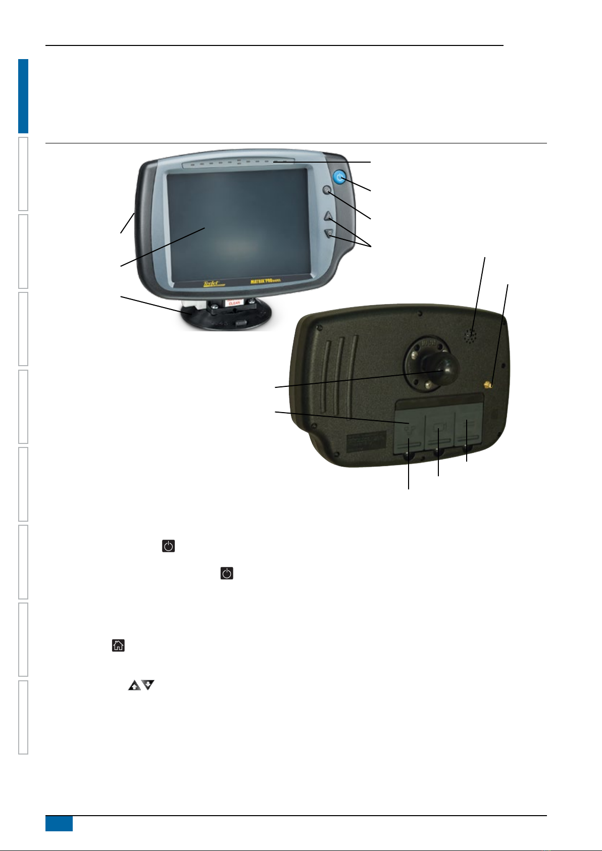
Matrix Pro 570GS console
The Matrix Pro 570GS is designed to provide years of service under typical agricultural operating conditions. A tight tting enclosure,
combined with rubber covers for all connectors mean that typical dusty environments will not cause operational problems. While
occasional splashing of water will not damage the unit, the Matrix Pro 570GS is not designed for direct exposure to rain. Take care not to
operate the Matrix Pro GS in wet conditions.
Figure 1-1: Matrix Pro 570GS console front and back
Power button
USB port with rubber cover
Rubber connector covers
GPS antenna connection
Integrated RAM mount
(assembly required)
Speaker
Recessed connectors
Speed digital connection
Camera connection
Power connection
Built in lightbar
Power button
USB port with rubber cover
Standard RAM bracket
(assembly required)
Bright touch screen
2www.teejet.com
MATRIX®Pro 570GS •MATRIX®Pro 840GS
HOME SETUP GUIDANCEFULL SCREEN IMPLEMENTGNSS RATE CONTROL APPENDIXINTRODUCTION
Matrix Pro 840GS console
The Matrix Pro 840GS is designed to provide years of service under typical agricultural operating conditions. A tight tting enclosure,
combined with rubber covers for all connectors mean that typical dusty environments will not cause operational problems. While
occasional splashing of water will not damage the unit, the Matrix Pro 840GS is not designed for direct exposure to rain. Take care not to
operate the Matrix Pro GS in wet conditions.
Figure 1-2: Matrix Pro 840GS console front and back
Built in lightbar
Power button
USB port
with rubber cover
Standard RAM bracket
(assembly required)
Bright touch screen
Home button
Zoom in/out buttons
Rubber connector
covers
GPS antenna
connection
Integrated RAM mount
(assembly required)
Speaker
Speed signal connection
Camera connection
Power connection
Buttons
Power on/off
On – Press the POWER button to power on the console. Upon
power up, the Matrix Pro GS will begin its start up sequence.
Off – Press and briey hold the POWER button until a
conrmation screen acknowledges shut down mode.
WARNING! Wait 10 seconds before restarting the console.
Home (Matrix Pro 840GS only)
The Home button provides a shortcut to the Home screen.
Up/Down (Matrix Pro 840GS only)
The Up/Down buttons adjust the vehicle’s view or
perspective to the horizon from vehicle view to bird’s eye view in
Vehicle View and Field View Guidance.
Additional information
All changes are saved automatically.
The console needs to be cycled off and back on when changing or
attaching equipment to the Matrix Pro GS system.
Start up sequence
The console takes approximately two minutes to power up. During
this time a series of screens will be displayed, LEDs will power on
and off, and brightness levels will uctuate. Once the power up
sequence has completed, the Home screen will appear.
Recommended antenna installation
The GNSS antenna should be mounted as far forward as possible
on top of the cab on a metal surface of at least 4 in / 10 cm
square.
3
98-05273-EN R7
MATRIX®Pro 570GS •MATRIX®Pro840GS
HOMESETUPGUIDANCE FULL SCREENIMPLEMENT GNSSRATE CONTROLAPPENDIX INTRODUCTION
RealView® camera
The TeeJet Technologies RealView camera allows video images
to be displayed on the Matrix Pro GS screen. The camera can be
pointed forward to enable RealView guidance over video, or it can
be positioned to view other operational aspects of your equipment.
The camera is equipped with a exible RAM mount, integral sun
shade and provides infrared illumination, allowing clear video
images even in dark conditions.
CONFIGURATIONS
The diagram that was in this location for previous software
versions has been moved to the appendix.
BASIC SCREEN USE
The Matrix Pro GS can be used as a simple current job system or advanced multi-job system. Regardless of which mode the console is
in, the basic screen functions are the same.
• Bottom Tabs and Side Tabs access the various screens and sub-screens
• Warnings and Information Pop-ups inform user of console activities and details on setup or guidance functions
• Setup options can easily be set using the drop-down menus or keyboard entry screens
To quickly nd a setup feature, see “Matrix Pro GS Console Menu Settings” in this manual.
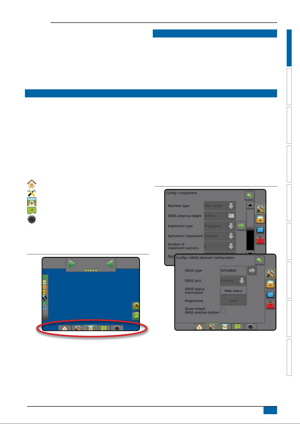
Bottom tab keys
The bottom tab keys are always available on screen. These keys
give access to jobs, setup options, and navigation.
Home/job screen
System setup
Vehicle view guidance
Field view guidance
RealView guidance or
RealView camera full screen video view
NOTE: RealView guidance options are only available with a
camera installed on the system.
Figure 1-3: Bottom tab keys
0.0
km/h
0.00
ha 0.0
Unavailable options when job is active
When a job is active some setup options are unavailable: see
“Matrix Pro GS Console Menu Settings” in this manual.
Figure 1-4: Examples of unavailable options

4www.teejet.com
MATRIX®Pro 570GS •MATRIX®Pro 840GS
HOME SETUP GUIDANCEFULL SCREEN IMPLEMENTGNSS RATE CONTROL APPENDIXINTRODUCTION
Console screen colours
The console is available in six colour schemes. From the System
Setup Bottom Key, press CONSOLE side tab and enter
the Display options. Press DOWN arrow to access the
Colour Scheme options to select colour mode.
Figure 1-5: Colour schemes
Simple or advanced mode
To change between simple mode and advanced mode, see the
conguration chapter under Data –> Options.
In simple mode, only one job will be available at a time. Only
bounded area and coverage areas are displayed on the home
screen. Only the current job is available for saving in Reports. Use
with Fieldware Link is not available.
Figure 1-6: Simple mode home screen
In advanced mode, more than one job will be available at any time.
Client, farm, eld and job names; bounded and coverage areas;
application time; and distance from selected job are displayed on
the home screen. All saved job proles can be exported as a PDF,
SHP or KML le to a USB drive using Data-> Reports.
Client information, farm information, eld information, and
prescription maps can only be inputted using Fieldware Link. A job
name can only be edited using Fieldware Link.
A user can duplicate jobs for reuse of guidelines, boundaries,
applied data, prescription map and/or polygons using Fieldware
Link or Data-> Job Data-> Manage in the console.
Figure 1-7: Advanced mode home screen
5
98-05273-EN R7
MATRIX®Pro 570GS •MATRIX®Pro840GS
HOMESETUPGUIDANCE FULL SCREENIMPLEMENT GNSSRATE CONTROLAPPENDIX INTRODUCTION
Warnings and information pop-ups
A pop-up warning or information box will be displayed for
approximately ve (5) seconds. To remove the information box, tap
anywhere on the screen.
Figure 1-8: Example of Information Text Box
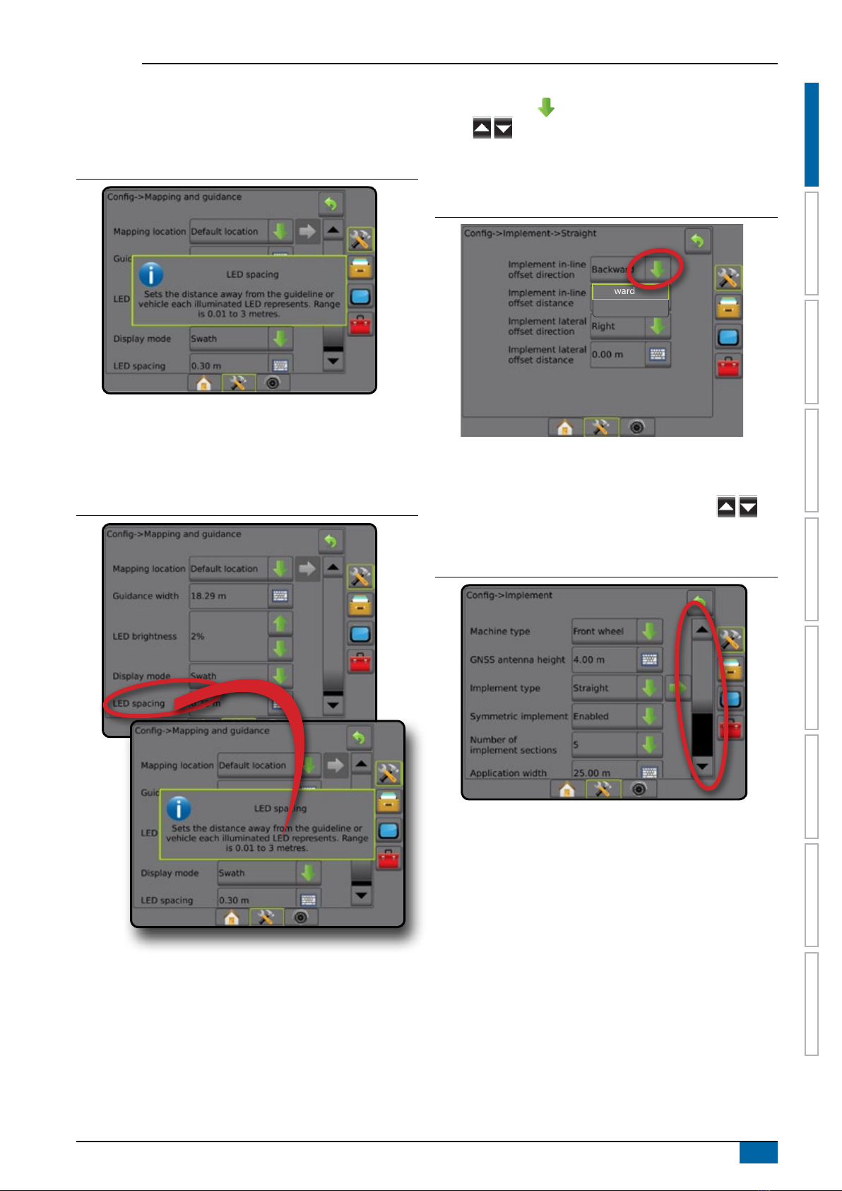
Setup option information
Press the option’s icon or option’s name of any menu item to
display a denition and range values of that item. To remove the
information box, press anywhere on the screen.
Figure 1-9: Example of Information Text Box
Drop-down menu selections
Press DOWN arrow to access the options. Use the UP/DOWN
arrows or slide bar if necessary to scroll through the
extended list. Select the appropriate option. To close the list without
selecting an option, tap anywhere on the screen outside the drop-
down menu.
Figure 1-10: Example of drop-down menu
Backward
Forward
Scrolling screens
Some screens have more information or options that are visible
beyond the current screen. Use the UP/DOWN arrows or
slide bar to access additional options or information not currently
visible on the screen.
Figure 1-11: Example of scrolling screen
6www.teejet.com
MATRIX®Pro 570GS •MATRIX®Pro 840GS
HOME SETUP GUIDANCEFULL SCREEN IMPLEMENTGNSS RATE CONTROL APPENDIXINTRODUCTION
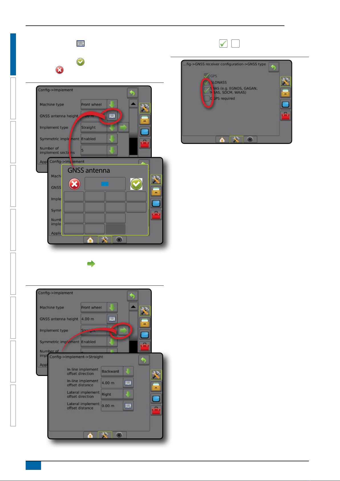
Keyboard entry screen
Press the KEYPAD icon . Use the numeric keypad to
enter a value.
Press the ACCEPT icon to save the settings or the
CANCEL icon to leave the keypad without saving.
Figure 1-12: Example of keyboard
GNSS antenna height (m)
123
12.5
Clear
456<--
789
0 . +/-
Next page
Press the NEXT PAGE arrow to set up additional options for
the selected item.
Figure 1-13: Example of next page
Checkboxes
Press the CHECKBOX / to select or deselect.
Figure 1-14: Examples of Checkboxes

7
98-05273-EN R7
MATRIX®Pro 570GS •MATRIX®Pro840GS
SETUPGUIDANCE FULL SCREENIMPLEMENT INTRODUCTIONGNSSRATE CONTROLAPPENDIX HOME
CHAPTER 2 JOBS / HOME SCREEN
Once the power up sequence has completed and the console is
receiving GNSS, the Home screen will appear with the option to
start a new job or continue an existing job.
Setup for the specic machine and its components
must be completed before starting a job. Once a
job is active, some setup options can no longer be changed. See
“Matrix Pro GS Console Menu Settings” in the appendix of this
manual.
To change between simple and advanced mode, go to Data->
Options-> Job Mode in the System Setup.
Simple mode
In simple mode, only one job will be available at a time. Only
bounded area, coverage areas, and application time are displayed
on the home screen. Only the current job is available for saving in
Reports. Use with Fieldware Link is not available.
Figure 2-1: Simple mode home screen
Advanced mode
In Advanced mode, more than one job will be available at any
time. Client, farm, eld and job names; bounded and coverage
areas; application time; and distance from selected job are
displayed on the home screen. All saved job proles can be
exported as a PDF, SHP or KML le to a USB drive using Data->
Reports.
Client information, farm information, eld information, and
prescription maps can only be inputted using Fieldware Link. A job
name can only be edited using Fieldware Link.
A user can duplicate jobs for reuse of guidelines, boundaries,
applied data, prescription map and/or polygons using Fieldware
Link or Data-> Job Data-> Manage in the console.
Figure 2-2: Advanced mode home screen
8www.teejet.com
MATRIX®Pro 570GS •MATRIX®Pro 840GS
SETUP GUIDANCEFULL SCREEN IMPLEMENTINTRODUCTION GNSS RATE CONTROL APPENDIXHOME
SIMPLE MODE
Once the power up sequence has completed, the Home screen
will appear with the option to start a new job or continue an
existing job.
The console must have GNSS before starting or continuing a job.
New job
Starting a new job will clear the previous job data.
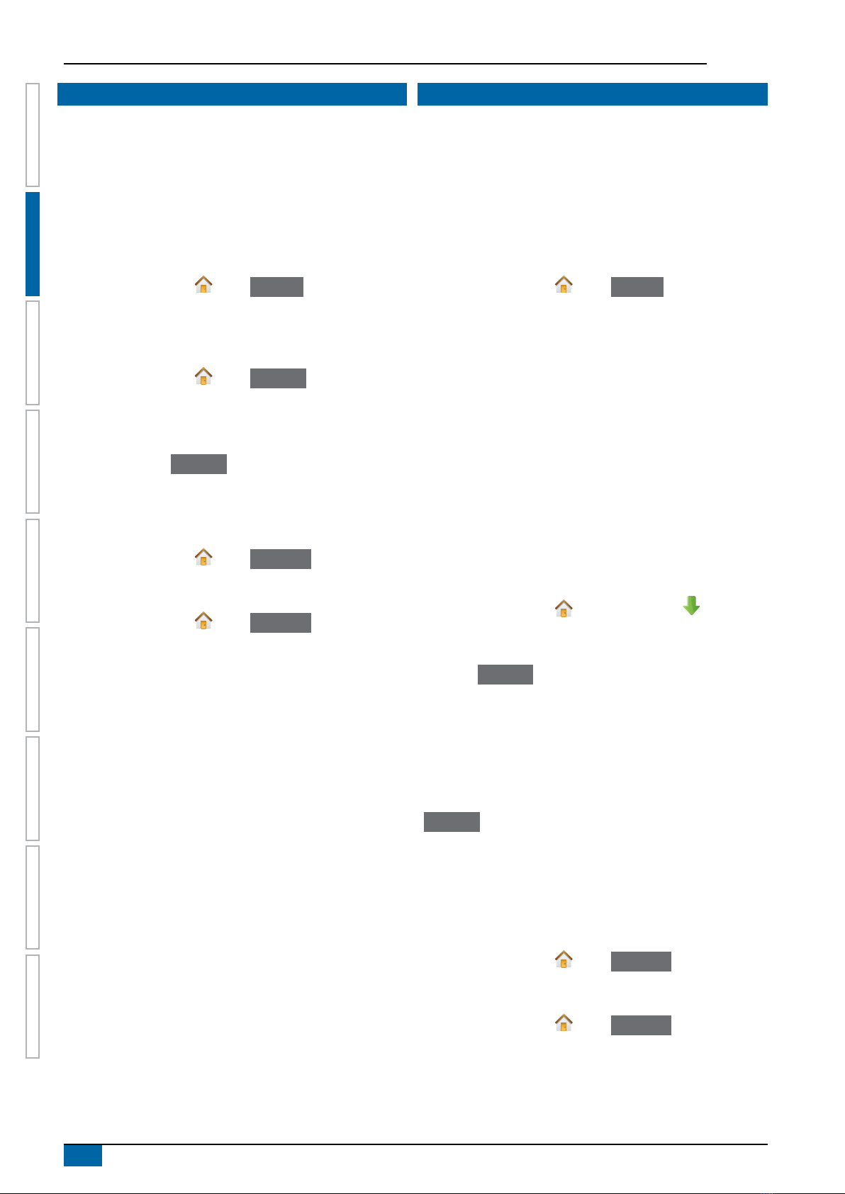
To start a New Job:
1. On the Home screen , press New Job .
The console will jump to Vehicle View.
Continue job
To continue the existing job:
1. On the Home screen , press Continue .
The console will jump to Vehicle View and begin providing
navigation information.
If a selected job is in a UTM zone other than the current or
adjacent UTM zone, Continue will be disabled.
NOTE: For more information, see the UTM Zone Appendix.
Close job
To close a job:
1. On the Home screen , press Close Job .
To create a report of the job when closing a job:
1. Insert a USB drive into the USB port of the console.
2. On the Home screen , press Close Job .
3. Select:
►Yes – to create a report of the last job
►No – to return to the Home screen without saving
ADVANCED MODE
Once the power up sequence has completed, the Home screen
will appear with the option to start a new job or continue an
existing job.
The console must have GNSS before starting or continuing a job.
New job
Starting a new job will clear the previous job data.
To start a New Job:
1. On the Home screen , press New Job .
2. Press:
►Yes – to automatically generate a name
►No – to enter a name using the on screen keyboard
Client, farm, and eld information are inputted using Fieldware
Link.
The console will jump to Vehicle View.
Start job
The Matrix Pro GS is programmed with a eld nder tool to assist
the user in nding the job closest to the vehicle’s location. With
GPS acquired, the job pick list will be updated every ten seconds.
During this update, the list of jobs is sorted by distance and the
closest two jobs are displayed on the top of the list. The remaining
jobs are listed beneath these.
To continue the existing job:
1. On the Home screen , press DOWN arrow to access
the list of jobs saved in the console.
2. Select the job name to be started/continued.
3. Press Start Job .
The console will jump to Vehicle View and begin providing
navigation information.
Distance
If a selected job is in a UTM zone other than the current or
adjacent UTM zone, “Out of Range” will be displayed next to
Distance, and
Start Job will be disabled.
NOTE: For more information, see the UTM Zone Appendix.
If a selected job has no recorded information, Distance will show
“No Data”.
Close job
To close a job:
1. On the Home screen , press Close Job .
To create a report of the job when closing a job:
1. Insert a USB drive into the USB port of the console.
2. On the Home screen , press Close Job .
3. Select:
►Yes – to create a report of the last job
►No – to return to the Home screen without saving

9
98-05273-EN R7
MATRIX®Pro 570GS •MATRIX®Pro840GS
HOMESETUPGUIDANCE IMPLEMENT INTRODUCTIONGNSSRATE CONTROLAPPENDIX FULL SCREEN
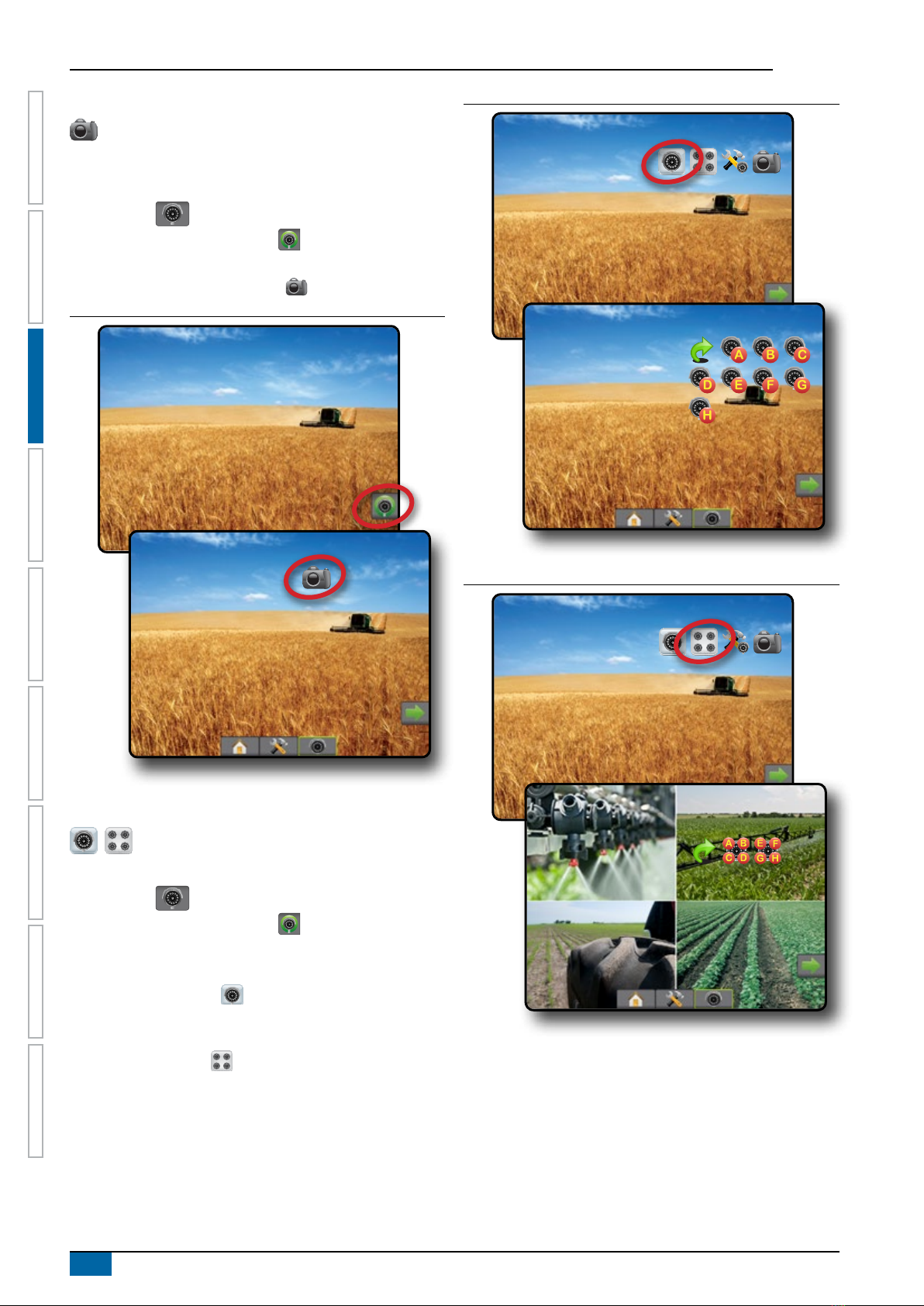
CHAPTER 3 FULL SCREEN VIDEO VIEW
RealView Full Screen Video View allows live video input to be displayed. View video feed(s) and setup cameras without GNSS available.
Options for RealView Guidance are not available on this screen.
►Single camera – a single camera is directly attached to the console
►Video selection module – if a Video selection module (VSM) is installed on the system, two (2) video options are available:
• One camera view – one of up to eight camera inputs can be selected to change the view of the video input.
• Split camera view – one of two sets of four camera inputs (A/B/C/D or E/F/G/H) can be selected to divide the screen into four
separate video feeds.
To adjust the camera view [reverse, upside down], go to Setup-> Conguration-> Video.
To enter Full screen video mode:
1. Press REALVIEW CAMERA FULL SCREEN VIDEO VIEW bottom tab .
2. Press REALVIEW OPTIONS tab to display RealView options.
3. Select from:
►Single camera view [VSM only] – one (1) of up to eight (8) camera inputs can be selected to change the view of the video
input
►Split camera view [VSM only] – one (1) of two (2) sets of four (4) camera inputs (A/B/C/D or E/F/G/H) can be selected to
divide the screen into four separate video feeds
►RealView camera image capture – saves a still photo of the current view on the screen to a USB drive
Figure 3-1: Realview full screen video view
10 www.teejet.com
MATRIX®Pro 570GS •MATRIX®Pro 840GS
HOME SETUP GUIDANCEIMPLEMENTINTRODUCTION GNSS RATE CONTROL APPENDIXFULL SCREEN
Camera snapshot
RealView camera snapshot saves a still photo of the current
view on the screen to a USB drive.
1. Insert USB drive.
2. Press REALVIEW CAMERA FULL SCREEN VIDEO VIEW
bottom tab .
3. Press REALVIEW OPTIONS tab to display RealView
options.
4. Press CAMERA SNAPSHOT icon .
Figure 3-2: RealView camera full screen video view
VSM camera options
If a Video selection module (VSM) is installed on the
system, two (2) video options are available:
1. Press REALVIEW CAMERA FULL SCREEN VIDEO VIEW
bottom tab .
2. Press REALVIEW OPTIONS tab to display RealView
options.
3. Select from:
►Single camera view – one (1) of up to eight (8) camera
inputs can be selected to change the view of the video
input.
►Split camera view – one (1) of two (2) sets of four (4)
camera inputs (A/B/C/D or E/F/G/H) can be selected to
divide the screen into four separate video feeds.
Figure 3-3: Single camera selection with VSM
Figure 3-4: Select split view with VSM
11
98-05273-EN R7
MATRIX®Pro 570GS •MATRIX®Pro840GS
HOMEGUIDANCE FULL SCREENIMPLEMENT INTRODUCTIONGNSSRATE CONTROLAPPENDIX SETUP
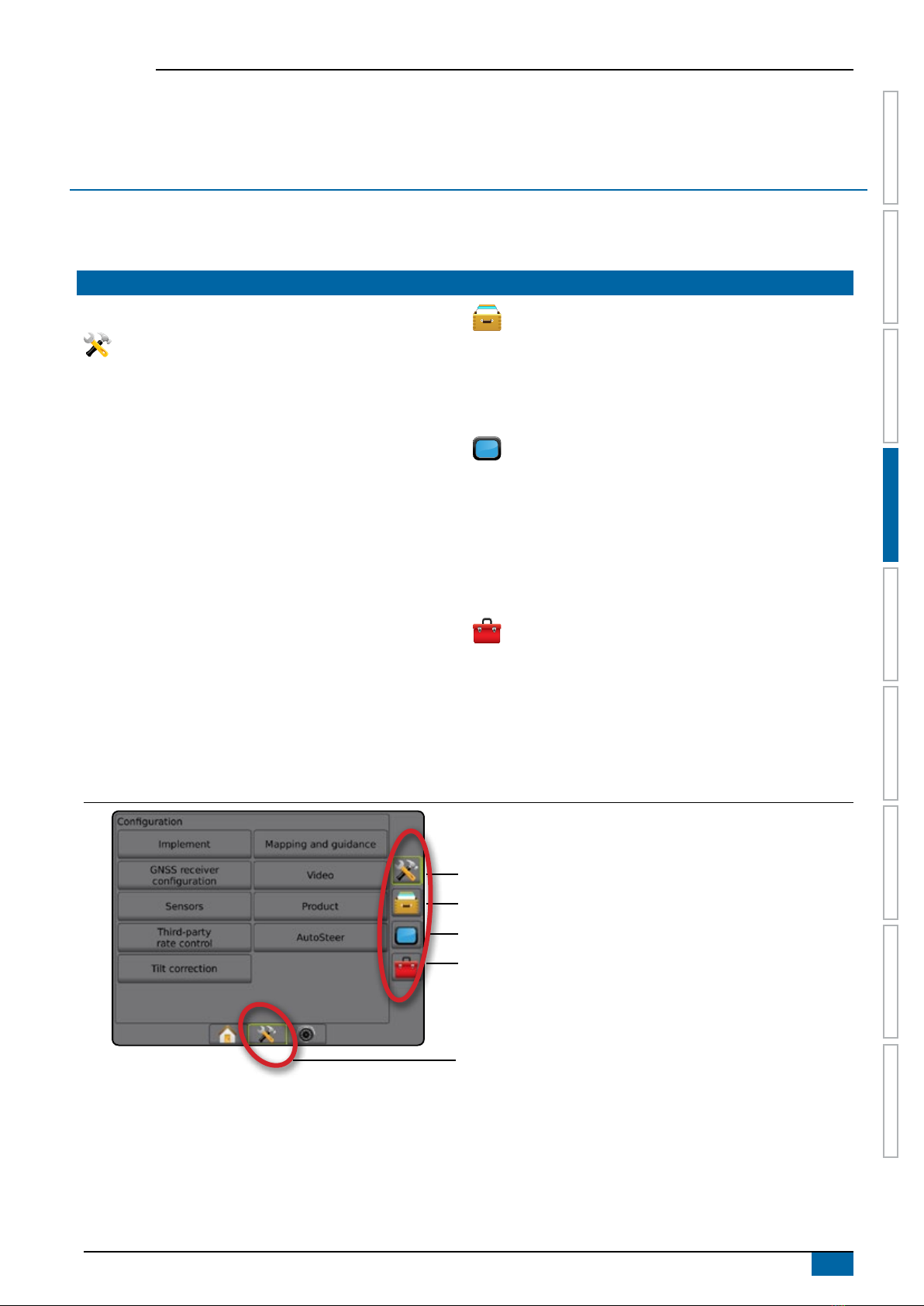
CHAPTER 4 SYSTEM SETUP
System Setup is used to congure the console, the machine and its implements. Four side tabs access options for Machine/Implement
Conguration, Data Management, Console Settings, and Tools.
OVERVIEW
Four side tabs access setup options for:
Conguration
• Implement (Straight, Spreader, or Staggered Implement
congurations; Nozzle Selection information including Droplet
Size Monitor, Reverse conguration)
• Mapping and guidance (Mapping Location, Lightbar, External
Lightbar)
• GNSS receiver conguration
• Video Conguration
• Sensors (Input/Output Module (IOM) Pressure Sensor)
• Product conguration
• Third-party rate control conguration
• AutoSteer
◄FieldPilot (Valve setup, Steering settings, Valve test, Valve
diagnostics, Steering wheel sensor, Steering angle sensor)
◄FieldPilot Pro / UniPilot Pro (Manage vehicle, Calibrations,
adjustments, Select QI values, Transport mode, Service
mode)
• Tilt correction
Data management
• Job data (transfer, manage)
• Reports
• Options (Job mode)
• Machine Settings (transfer, manage)
Console settings
• About (system information)
• Display
• Cultural
• Audio volume
• Demo GNSS
• Feature unlock
Tools
• Upload software
• Extras (calculator, units converter)
Figure 4-1: Setup options
Conguration side tab
Data Management side tab
Console Settings side tab
Tools side tab
System Setup bottom tab
Side tabs
12 www.teejet.com
MATRIX®Pro 570GS •MATRIX®Pro 840GS
HOME GUIDANCEFULL SCREEN IMPLEMENTINTRODUCTION GNSS RATE CONTROL APPENDIXSETUP
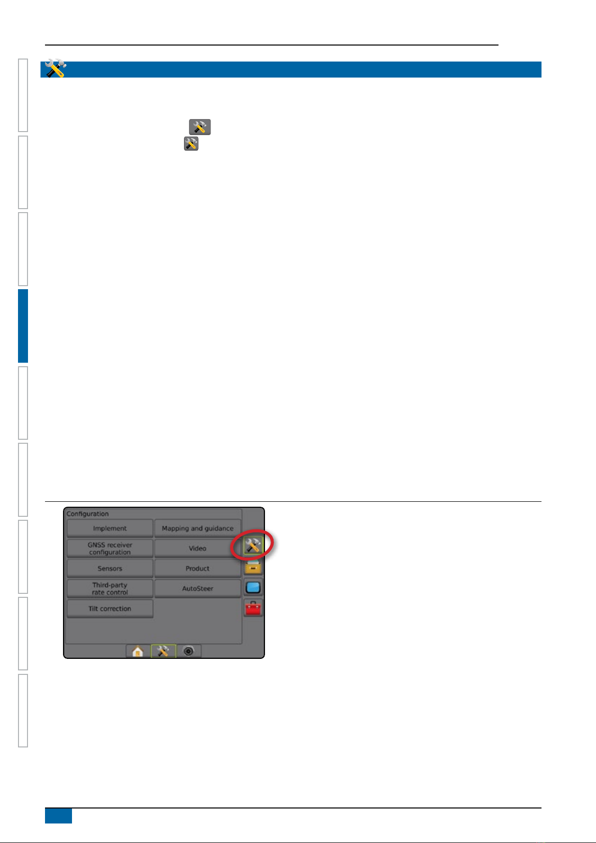
CONFIGURATION
Conguration is used to congure the system components including implements, guides, steering, monitors and sensors.
NOTE: Feature availability will vary depending on the devices available and unlocked on the Matrix Pro GS system.
1. Press SYSTEM SETUP bottom tab .
2. Press CONFIGURATION side tab .
3. Select from:
►Implement – used to set (as appropriate) machine type,
GNSS antenna height, implement type, symmetric
implement layout, section output modules, number of
implement sections, application/working width, droplet size
monitor, nozzle selection, nozzle spacing, BoomPilot start
mode, Reverse Sense Module
● In Straight mode – in-line/lateral implement offset
direction/distance, overlap percentage, implement delay
on/off time
● In Spreader mode:
TeeJet – antenna to disks distance, lateral implement
offset direction/distance, overlap percentage, delay on/
off times, spread offset distance, section offset distances,
section lengths
OEM – antenna to disks distance, lateral implement offset
direction/distance, start/stop distance, section start/stop
offset distances
● In Staggered mode – in-line/lateral section 1 offset
direction/distance, overlap percentage, delay on/off times,
section offsets
►Mapping and guidance – used to congure the mapping
location, guidance width, cross track error shown on the
lightbar
►GNSS receiver conguration – used to establish GNSS type,
port, and PRN, as well as to view GNSS status information
►Video – used to set up individual cameras
►Sensors – used to establish pressure sensor settings
►Product – used to congure product name, colour mapping
maximum/minimum rate limits and corresponding display
colours
►Third-party rate control settings – used to congure
hardware interface and communication.
►AutoSteer – used to enable/disable and calibrate assisted/
auto steering
● FieldPilot – used to establish valve setup settings, steering
settings, steering wheel and steering angle sensor
settings, and to perform valve tests or valve diagnostics
● FieldPilot Pro / UniPilot Pro – used to manage vehicle
settings, calibrate sensors, select QI values, as well as
establish transport mode and service mode
►Tilt correction – used to enable/disable and calibrate the
tilt correction function, and improve application on hilly or
sloped terrain
Figure 4-2: Configuration options
This manual suits for next models
1
Table of contents
Other TeeJet GPS manuals


