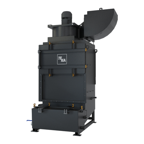
Teka Spark User manual

Table of contents
1 General 3
2 Description of the system elements 4
2.1 Illustration of the system elements 4
2.2 Intended use 5
3 Safety instructions 6
3.1 Definition of the hazard symbols 6
3.2 General safety instructions 6
4 Storage, transport and installation of the device 7
5 Commissioning 8
5.1 Connecting the suction line and exhaust air line 8
5.1.1 Positioning the perforated sheet 9
5.2 Electrical connection 9
5.3 Water supply / water quality 10
6 Operating the system 11
6.1 Explanation of the operating elements 11
6.2 Functioning of the control system 11
6.3 Error reporting of the control system 12
6.4 Set the sensitivity of the level monitoring relay 12
7 Maintenance 13
7.1 Reset to maintenance state 13
7.2 Cleaning the dust collecting tank 14
7.3 Cleaning of the spark separator 14
7.4 Maintenance of the filling level sensors 14
8 Dismantling / Disposal 15
9 List of spare parts 15
10 Technical data 15
11 EC declaration of conformity (according to 2001/95/EC) 16
12 Maintenance intervals 17
BA_Funkenvorabscheider_171107_EN
2
11.01.2022

12.1 Usage-related maintenance 17
12.2 General maintenance 17
12.2.1 Visual inspection of the device 18
12.2.2 Visual inspection of the pipelines for dust deposits 18
12.2.3 Electrical test of the electrical lines and earthing connections 18
1 General
Congratulations on purchasing the product from TEKA.
Our engineers ensure that our devices reflect the state of the art through continuous development.
Nevertheless, misuse or misconduct can endanger your safety. Please observe the following for a
successful use of the device:
Only authorised and instructed personnel can carry out transport, operation,
maintenance and repair of the device. The operator must ensure that the operating
personnel take note of these instructions.
Please read these instructions before operating the device, and observe the safety
precautions to avoid injury!
Store this manual in a safe place! These instructions are to be regarded as a component
of the product!
Adhere to all product notes!
Modifications or conversions that the operator carries out at the device without the
consent of the manufacturer, can lead to new safety hazards or to the loss of warranty
claims.
Observe the manufacturer’s instructions. Contact the manufacturer in case of any
uncertainty:
Tel: +49 2541-84841-0
E-mail: [email protected]
BA_Funkenvorabscheider_171107_EN
3
11.01.2022

2 Description of the system elements
2.1 Illustration of the system elements
Installation example:
Z.Nr. 11283702
Pos.1
Pos.2
Pos.3
Pos.4
Pos.5
Pos.6
Pos.7
Pos.8
Operating panel of the control
Connection for mains cable
Exhaust air nozzle*
Suction nozzle* (air inlet side)
Dust collecting tank (filled with water)
Toggle lever
Ball valve ¾“ for water connection
Wastewater connection ¾”
Pos.9
Pos.10
Pos.11
Pos.12
Pos.13
Pos.14
Pos.15
Pos.16
Magnet valve
Service door
Filling level sensor 3-pin
Filling level sensor 1-pin
Housing for filling level sensor
Optical filling level indicator
Perforated sheet (exhaust air side)
Bar heater (option)
* = which is the suction nozzle and which the exhaust air nozzle is defined at the time of assembly (see
section “Connecting the suction line and exhaust air line”).
BA_Funkenvorabscheider_171107_EN
4
11.01.2022

2.2 Intended use
The device is intended for commercial use. If the device is made publicly accessible, it must never be
operated unsupervised by authorized personnel, authorized by the operator.
The TEKA spark separator is a safety device to protect the filtering unit from sparks and glowing
particles, especially during welding. The sparks are extinguished when the air flow strikes the surface of
the water. Light particles are also moistened with water through the simultaneous air deflection within
the housing.
WARNING
Dangers arising from fire.
If the sucked medium is combustible fume or dust, the operator must determine beforehand
which fire protection measures are to be taken.
BA_Funkenvorabscheider_171107_EN
5
11.01.2022

3 Safety instructions
3.1 Definition of the hazard symbols
The device is constructed according to the state of the art and the recognised safety regulations.
Nevertheless, during use threats to life and limb of the user or other persons may arise. The impairment
of the machine or other property are also possible. In these instructions we warn by using corresponding
indications.
WARNING
WARNING
These instructions are made in case of risks that can lead to injury or death.
CAUTION
CAUTION
These instructions are made in case of risks that can lead to injury.
NOTICE
NOTICE
These instructions are made in case of risks that can lead to material damages.
Information notes are no hazard warnings; they call attention to useful information.
3.2 General safety instructions
WARNING
Dangers arising from improper use / unauthorised operations.
The operator must ensure that their authorised personnel are familiar with all the safety
indications in this manual in advance. The operator is responsible for ensuring that all work
is carried out by authorised and qualified personnel.
Laymen are allowed to operate the device after having received the necessary instructions.
But they are not allowed to carry out any installation, repair or maintenance work.
Dangers arising from fire.
In case of fire, if possible, switch the unit immediately off or disconnect it from the power
supply. Fire extinguishing measures which the operator is obliged to determine beforehand
must be initiated immediately.
WARNING
Dangers arising from electricity.
The operator must ensure that electrical plants and equipment are only built, modified and
maintained by a qualified electrician or under the direction and supervision of a qualified
electrician. Do not work on components if you are not sure that these are disconnected. If
necessary, disconnect the device from the electric power supply and secure it against
unauthorized restarting.
BA_Funkenvorabscheider_171107_EN
6
11.01.2022

4 Storage, transport and installation of the device
WARNING
Risk of injury from tilting or unmounted components when stored or transported.
The device must be secured against tilting and slipping when it is stored or transported. Do
not stand under or next to the floating load. Lift trucks, forklift trucks and transport cranes
must have a sufficient minimum load bearing capacity.
Dangers arising from titling or functional impairments at its destination.
The unit may only be set up on a suitable surface. The unit may only be set up on a suitable
surface. The surface must be vibration-free and horizontal. The operator must check the
bearing capacity of the surface. The unit must be secured on the surface, for example using
lag bolts or heavy-duty anchors.
NOTICE
Damage or functional impairment of the unit due to climatic influences.
The unit must be stored in a dry place and protected against moisture during transport. As a
matter of principle, the filter unit is not designed to be installed outside.
If the unit still be placed in the outdoor area, the dust collecting tank be equipped with a
heating element (bar heater, see chapter 2.1). In case of outdoor installation the magnet
valve (see chapter 2.1) must also be installed inside the building. The operator has to ensure
that the water supply of magnet valve for spark separator remains frost-free.
If the unit is placed in the outdoor area, the filter level control must be dismantled and placed
indoors. The control and measurement cables to the spark separator are embarrassed to
meet new or renew.
BA_Funkenvorabscheider_171107_EN
7
11.01.2022

5 Commissioning
WARNING
Dangers arising from a defective condition of the unit.
Make sure that the measures described in this chapter are completed before the
commissioning of the unit. All doors of the unit must be closed and all necessary connections
must be attached before turning the unit on. Do not operate the unit if any components are
defective, missing or damaged. Check the orderly condition of the unit before switching it on.
NOTICE
Damaged supply lines.
Make sure that the supply lines are protected against damage by forklift trucks and similar
events. Protect all supply lines from heat, moisture, oil and sharp edges.
5.1 Connecting the suction line and exhaust air line
For extracting the contaminated air, a suction line must be connected to the suction nozzle (see chapter
2.1).
CAUTION
Danger for the respiratory tract arising from polluted ambient air. Dust deposits in the
suction pipe are possible.
Only operate the system if the necessary suction line is fitted. The suction line must be
dimensioned according to the application in such a way that, if possible, no dust deposits
occur in the suction line. If this has not already been carried out by TEKA, a suitably qualified
employee must be consulted. If the suction line includes extraction elements (e.g. suction
arms, pipe grills, etc.), these must also be included in the layout. If this is the case then users
must be informed of whether extraction elements can be used simultaneously and, if this is
possible, then which. The regulating devices (e.g. throttle valves) of each single extraction
element must also be set appropriately during the final commissioning.
The exhaust air pipe must be attached to the exhaust nozzle (see chapter 2.1). (The exhaust air line
connects the spark separator to the filter unit.)
BA_Funkenvorabscheider_171107_EN
8
11.01.2022

5.1.1 Positioning the perforated sheet
If the perforated sheet (see chapter 2.1) is to fulfil its function it must be mounted on the exhaust air
side, i.e. on the side on which the exhaust air nozzle is located (see section 2.1). Before taking the
equipment into service, it is therefore necessary to check that the perforated sheet is mounted on the
correct side.
● Open the service door (see chapter 2.1).
● If this has not already been done, position the perforated sheet on the exhaust air side. Push
the perforated sheet fully into the guide.
Make sure that the handle is at the front.
5.2 Electrical connection
WARNING
Risk of electric shock.
Electrical plants and equipment may only be built, modified and maintained by a qualified
electrician or under the direction and supervision of a qualified electrician. Do not work on
live electrical components and elements if you are not sure that these are indeed
disconnected. If necessary, disconnect the device from the mains. The operator is
responsible for a potential-free balance of the equipment.
NOTICE
Electric malfunction possible in cause of an incorrect power supply.
Pay attention to the admissible supply voltage. Please observe the specifications on the type
plate.
● Connect the mains cable (see chapter 2.1) to the power supply.
BA_Funkenvorabscheider_171107_EN
9
11.01.2022

5.3 Water supply / water quality
Due to the moistening of the outlet air, the water is little by little extracted from the filter unit. That is why
water must be regularly be refilled. It is ensured by the automatic monitoring of the water level and the
automatic refilling through the electrovalve.
WARNING
Danger due to unhealthy exhaust air released by contaminated water.
Make sure that the supplied water is of irreproachable hygienic and microbiological quality.
The supplied water must be clear, colourless and odourless. The water must also be
“non-putrefactive in 5 days”.
Equally, in the event of a system stoppage lasting 5 or more days, the operator must check
whether the water still meets the quality requirements or whether it needs to be changed. As
soon as an extended stoppage of the system is envisaged, it is urgently recommended to
drain off the water for this period.
The operator must also make sure that the admixture of the water with the extracted
dusts/fumes does not result in any interactions that jeopardize fulfilment of the above quality
requirements.
NOTICE
Possible damage to equipment (valves, supply line, etc.) due to contaminated water.
Make sure that the supplied water is free from suspended matter and other contaminants.
● During operation, the ball valve (see chapter 2.1) has to be equipped with an open water supply
of ¾“.
● When carrying out cleaning operations, you have to pay attention that no polluted water enters
the canalisation.
● Before switching on the unit for the first time, it is advisable to let in water manually until the
water level reaches the middle of the water level indicator.
BA_Funkenvorabscheider_171107_EN
10
11.01.2022

6 Operating the system
6.1 Explanation of the operating elements
Operating elements for the device control
Representa
tion
Designation
Description / function
ON-OFF-switch
By means of this switch, the device is switched on and
off. The control is now ready for operation and begins
automatically with the level control of the dust collecting
tank.
When the device is switched off, it is not
disconnected from the power supply.
Operating elements for status and error messages
Representa
tion
Designation
Description / function
“Betrieb / Operation”
The light indicator operation gives an optical response
when the control is supplied with the mains voltage.
“Befüllen / Filling”
The light indicator filling gives an optical response when
the magnet valve is opened for the filling of the system.
The light indicator extinguishes when the maximum
nominal level is reached.
Signal horn
Honking signals that the unit signals an error.
6.2 Functioning of the control system
After switching on the power at a level below the maximum nominal level, the normally open contact of
the level monitoring relay goes into the operating position, the magnet valve for the filling of the system
is opened and the filling process is started. When reaching the maximum nominal level and after the
expiry of the overrun time the relay is switched off and the magnet valve is closed. If the level is below
the minimum nominal level, the relay goes on again and remains engaged till the maximum nominal
level is reached.
BA_Funkenvorabscheider_171107_EN
11
11.01.2022

6.3 Error reporting of the control system
The duration of the valve opening to fill the system is monitored via the time control relay (t = 30s). If the
maximum nominal level is not reached within a specified period of time, the magnet valve will be closed
and an acoustic signal is emitted by the horn. The reset of the malfunction is possible as follows:
● Manual filling of the dust collecting tank till the maximum nominal level is reached.
● Restarting the system.
An acoustic trouble signal by the horn can also be triggered when there is too much water in the spark
separator. In this case the filling level sensor has triggered. The reset of the malfunction can be carried
out as follows:
● Empty the water to a normal water level. The way of proceeding is described in chapter
“Cleaning of the dust collecting tank”.
● Restarting of the system.
6.4 Set the sensitivity of the level monitoring relay
The sensitivity of the level monitoring relay is preset by TEKA. In case of exchange or inappropriate
switching behaviour of the level monitoring relay the sensitivity must be reset.
● For the commissioning of the level monitoring relay the function FS (pos. 1) is chosen and the
sensitivity (pos. 2) is set on the lowest value of 5 kΩ. During that all probes must be immersed
in the liquid. The potentiometer for the sensitivity is turned in the direction of 150 kΩ till the
monitoring relay is safely switched off and the red LED blinks slowly. Finally it should be
checked if the level monitoring relay works as requested.
BA_Funkenvorabscheider_171107_EN
12
11.01.2022

7 Maintenance
In accordance with national regulations, the operator is obliged to carry out repeat and functional tests.
Unless otherwise specified by national regulations, we recommend regular visual inspections and
functional tests of the device as described in the chapter “Maintenance intervals”.
You find the chapter “Maintenance intervals” at the end of the document. The general
maintenance (visual inspection, etc.) is also explained there.
In this chapter the maintenance work which is caused by wear caused during operation is described.
WARNING
Work on the open system entails the risk of electrical shock or accidental restart the
system. Both pose a danger to life and limb.
When cleaning and servicing equipment during the replacement of parts or when changing
to another function, set the device to maintenance condition first (see chapter “Reset to
maintenance state”).
A recommissioning of the device must only occur if it is ensured that the device is
functionally equivalent to the original state.
The operator is obliged to store and dispose of the collected dust in accordance with national or
regional regulations. For all maintenance or cleaning work please refer to the applying
environmental regulations. Pollutants and filter elements must be disposed of or stored according
to the regulations as well. If you have any doubts, we recommend contacting a disposal
contractor in your area.
7.1 Reset to maintenance state
● Switch off the unit. Secure the unit against unauthorized restarting during maintenance.
When the device is switched off, it is not disconnected from the power
supply.
● After completion of all maintenance work the unit can be switched on again.
BA_Funkenvorabscheider_171107_EN
13
11.01.2022

7.2 Cleaning the dust collecting tank
The dust collection container must be cleaned after a certain number of operating hours. This range
depends on the amount of dust. The filling level has to be proofed at least once a week.
● The connection of the filling level sensors (see chapter 2.1) has to be dismounted from the
housing (see chapter 2.1).
● Open the toggle levers (see chapter 2.1) of the dust collecting tank and pull these out from
under the spark separator.
● Open the ball valve (see chapter 2.1) to release the water from the dust collecting tank. A drain
hose can be connected to the ball valve. Otherwise position the ball valve over a suitable water
drainage device. In case of cleaning work attention should be paid that no water contaminated
with pollutants can enter into the sewage system.
● Clean as well the filling level sensor’s housing by removing the cap. Pay attention that the
measurement electrodes of the sensor are not damaged.
● After cleaning the container push it back under the spark separator and secure with the toggle
fasteners. Take care not to damage the gasket.
● The connection of the filling level sensor has to be mounted from the water dust tank.
7.3 Cleaning of the spark separator
● Open the service door (see chapter 2.1) by loosening the locks.
● Make sure that during cleaning processes no polluted water gets into the drainage system.
● Remove all remaining dust particles on the perforated sheet (see chapter 2.1).
● Clean the interior space of the spark separator.
● Reinsert the perforated sheet into the guide rails (exhaust air side) and lock the door.
7.4 Maintenance of the filling level sensors
The filling level sensors (see chapter 2.1) have to be inspected regularly concerning wear and
calcination. If necessary the sensors have to be cleaned or changed.
BA_Funkenvorabscheider_171107_EN
14
11.01.2022

8 Dismantling / Disposal
Only authorised personnel may disassemble the machine.
WARNING
Dangers arising from electricity.
Before the dismantling of the machine it has to be disconnected from the power supply and
all supply lines.
The operator is obliged to store and dispose of the collected dust in accordance with national or
regional regulations.
9 List of spare parts
Other parts
Article no.
Magnet valve, 230 V AC
200421310340010
Filling level sensor 3-pin
100421120210028
Filling level sensor 1-pin
100421120210042
10 Technical data
Version
1000 - 3000
4000 - 6000
7000 - 12000
Control system
Supply voltage: 230 V
Frequency: 50 Hz
Type of current: L+N+PE
Width
Depth
Height
mm
mm
mm
760
560
1450
960
760
1450
1260
1060
1450
Weight (without water filling)
kg
ca. 115
ca. 150
ca. 200
Water filling during operation
L
25 - 35
50 - 80
110 - 170
Water supply
Hose nozzle ¾“
Required water pressure min./max.
bar
0,3 / 16
BA_Funkenvorabscheider_171107_EN
15
11.01.2022

11 EC declaration of conformity (according to 2001/95/EC)
TEKA Absaug- und Entsorgungstechnologie GmbH
Millenkamp 9, D-48653 Coesfeld
Designation of the device: TEKA spark separator
We declare under our sole responsibility that the following guidelines have been applied for the above
mentioned product:
Electromagnetic Compatibility: 2014/30/EC
Low Voltage Directive: 2014/35/EU
This declaration will become void if the device is exposed to modifications that are not approved by the
manufacturer in written form.
Authorized representative for the technical documentation:
TEKA Absaug- und Entsorgungstechnologie GmbH, Millenkamp 9, D-48653 Coesfeld
(Jürgen Kemper, managing director)
Coesfeld, 3rd january 2017
BA_Funkenvorabscheider_171107_EN
16
11.01.2022

12 Maintenance intervals
12.1 Usage-related maintenance
The described maintenances become necessary through the demands of the system operations. The
maintenance intervals are recommendations. Depending on the application (multi-shift operation, dust
generation, ...) it may make sense for the operator to change the intervals of maintenance, replacing
and cleaning.
Maintenance work must always be documented by means of a protocol.
The approach of the maintenance measures is described in chapter "Maintenance".
Maintenance work
Chapter
Maintenance interval
recommended by TEKA
determined by the operator
Cleaning the dust collecting tank (or
check of fill level)
7.2
weekly
Cleaning of the spark separator
7.3
monthly
Maintenance of the filling level
sensors
7.4
monthly
12.2 General maintenance
The described maintenances are independent from the demands of the system operations.
The operator is obliged to carry out repeated inspections and functional tests according to national
regulations. If not otherwise covered by national regulations, the described maintenance intervals must
be respected.
Maintenance work must always be documented by means of a protocol.
Maintenance work
Chapter
Maintenance interval
Visual inspection of the device
12.2.1
weekly
Visual inspection of the pipelines for dust deposits
12.2.2
monthly
Electrical test of the electrical lines and earthing connections
12.2.3
annually
BA_Funkenvorabscheider_171107_EN

17
11.01.2022

12.2.1 Visual inspection of the device
Visual inspection: Observation that there are no visible safety-related defects.
WARNING
Danger arising from the ready to operate condition of the device.
Follow the procedure as described in the chapter “Set to maintenance state”.
The following steps must be carried out in the course of the visual inspection:
● Check if all required pipeline elements, cable connections and hoses are connected to the filter
unit
● Check all electrical earthing connections and cables for visible damages.
● Ensure that all parts are firmly connected.
● Check all metal parts for corrosion or damages / changes of the coating.
12.2.2 Visual inspection of the pipelines for dust deposits
Visual inspection: Observation that there are no visible safety-related defects.
WARNING
Danger arising from the ready to operate condition of the device.
Follow the procedure as described in the chapter “Set to maintenance state”.
The following steps must be carried out in the course of the visual inspection:
● Open the inspection flaps of the pipeline and check the pipeline for dust deposits. Dust deposits
must be eliminated.
12.2.3 Electrical test of the electrical lines and earthing connections
WARNING
Danger arising from electricity.
The operator is responsible for ensuring that all work on electric components is carried out
by authorised and qualified personnel.
The device is subject to regular electrical checks by the operator of the device, and are subject to
national standards of the different countries.
The here recommended maintenance interval complies with the in Germany applying "Regulation 3 of
the German Social Accident Insurance - Electrical plants and equipment" (formerly known as BGV-A3).
The check must only be carried out by a qualified electrician or a person trained in electrics using
suitable measuring and test devices. The scope of testing and the methods must be in line with the
respective national standard. All contacts in the control cabinet must be checked for tight fit, and must
be readjusted if necessary.
BA_Funkenvorabscheider_171107_EN

18
11.01.2022
This manual suits for next models
1
Table of contents
Other Teka Water Filtration System manuals
Popular Water Filtration System manuals by other brands

Lectranator Systems
Lectranator Systems CRISTAL MAGIC CM3-1 Installation & operation manual

Oase
Oase FiltoClear 5000 operating instructions

Eriez
Eriez FF4 Installation, operation and maintenance instructions

DH Instruments
DH Instruments 1-2 IN. FILTER KIT instruction sheet

Pentair
Pentair FLECK 5800 SXT Service manual

Parker
Parker Sentinel user manual

Millipore
Millipore milli-q user manual

Schier
Schier PP2 installation guide

Pentair
Pentair EVERPURE EZ-RO 200/2G Installation & operation guide

Novy
Novy 6830060 installation instructions

Eureka Forbes
Eureka Forbes Aquaguard select AWS C2500 DX user manual

Clean Water
Clean Water 7500-REV4 installation guide