logo
Brands
  1. Home
  2. •
  3. Brands
  4. •
  5. Lenze
  6. •
  7. Keypad
  8. •
  9. Lenze AC Tech 844-240 User manual

Lenze AC Tech 844-240 User manual

Other Lenze Keypad manuals

Lenze ESMD01KP User manual

Lenze

Lenze ESMD01KP User manual

Lenze EPM-H315 User manual

Lenze

Lenze EPM-H315 User manual

Lenze EPM-H410 User manual

Lenze

Lenze EPM-H410 User manual

Lenze KF01G User manual

Lenze

Lenze KF01G User manual

Lenze E82ZBHT User manual

Lenze

Lenze E82ZBHT User manual

Lenze EPM-H310 User manual

Lenze

Lenze EPM-H310 User manual

Lenze E82ZBC User manual

Lenze

Lenze E82ZBC User manual

Lenze SCL series User manual

Lenze

Lenze SCL series User manual

Lenze E94AZKAE User manual

Lenze

Lenze E94AZKAE User manual

Lenze EPM-H410 User manual

Lenze

Lenze EPM-H410 User manual

Popular Keypad manuals by other brands

ACT ACT PRO 1030 manual

ACT

ACT ACT PRO 1030 manual

Cardin SSB Series manual

Cardin

Cardin SSB Series manual

Harman Kardon KP 1 Specifications

Harman Kardon

Harman Kardon KP 1 Specifications

Chamberlain KPR2000 Installation setup manual

Chamberlain

Chamberlain KPR2000 Installation setup manual

CYP CR-KP1 Operation manual

CYP

CYP CR-KP1 Operation manual

Aeware k-35 Series Quick reference card

Aeware

Aeware k-35 Series Quick reference card

Aritech CS-175 Series user guide

Aritech

Aritech CS-175 Series user guide

GE NetworX NX-1600E Series user manual

GE

GE NetworX NX-1600E Series user manual

Lenze AC Tech MC SERIES installation instructions

Lenze AC Tech

Lenze AC Tech MC SERIES installation instructions

Burg Wächter secuENTRY 7711 operating instructions

Burg Wächter

Burg Wächter secuENTRY 7711 operating instructions

Aeware in.k450 Tech book

Aeware

Aeware in.k450 Tech book

Toshiba RKP007Z user manual

Toshiba

Toshiba RKP007Z user manual

Gemini GEM-DXK1 KEYPAD operating guide

Gemini

Gemini GEM-DXK1 KEYPAD operating guide

Russound MDK-C5 User and installation manual

Russound

Russound MDK-C5 User and installation manual

Bosch D1260 Series installation guide

Bosch

Bosch D1260 Series installation guide

Elmes Electronic KB1 quick start guide

Elmes Electronic

Elmes Electronic KB1 quick start guide

Clare Controls ClareOne CLR-C1-PNC Installation sheet

Clare Controls

Clare Controls ClareOne CLR-C1-PNC Installation sheet

Bosch DS7446KP user guide

Bosch

Bosch DS7446KP user guide

https://manuals.online logo
https://manuals.online logoBrands
  • About & Mission
  • Contact us
  • Privacy Policy
  • Terms and Conditions

Copyright 2025 Manuals.Online. All Rights Reserved.

3. MOUNTING THE REMOTE KEYPAD
e diagram below illustrates how to mount the remote keypad to a panel. Use the
template in Section 2 to mark the location of the mounting holes on the panel.
2. SCL/SCM REMOTE KEYPAD TEMPLATE
Hold this page against the panel where the remote keypad is to be mounted, and
use a center punch to mark the location of the holes. e dotted line is the outline
of the remote keypad.
SCL/SCM SERIES REMOTE KEYPAD
INSTRUCTIONS
(Manual Number: KM01A-e1)
e SCL/SCM Series Remote Keypad option (#844-240) allows the SCL/SCM
Series drive to be programmed and controlled from up to 8 feet away (typically
from the front of the enclosure that houses the SCL/SCM drive). When properly
mounted, the remote keypad is rated up to NEMA 4X.
In addition to the functions available on the front of the SCL/SCM drive, the
remote keypad has Start/Stop and Forward/Reverse functions.
NOTE: e Remote Keypad option will only work with SCL/SCM drives that have
parameter version “320” or higher. e parameter version appears momentarily
on the drive display when it is powered up, and also appears on a sticker on the
drive’s heatsink.
1. PARTS LIST
e SCL/SCM Remote Keypad kit includes the following parts:
(1) Remote Keypad (1) Gasket
(2) Self-tapping Mounting Screws (1) Instruction Sheet
(1) Eight foot cable
NOTE: e supplied cable is unshielded and can only be used in low-noise
environments. In high-noise environments, use Belden 9842, Carol C4842, or
equivalent (24 gage minimum) wire only. e maximum cable length that can
be used is 8 feet.
1/8” hole
1/8” hole
1.57”
1.32”
1.38” to 1.5”
hole
3.38”
2.19”
UP
Max Depth = 0.72”
4. WIRING CONNECTIONS
NOTE: e supplied cable is unshielded and can only be used in low-noise
environments. In high-noise environments, use Belden 9842, Carol C4842, or
equivalent (24 gage minimum) wire only. e maximum cable length that can
be used is 8 feet.
REMOTE KEYPAD
(BACK VIEW)
13B
13E
11
2
UP
125611 13A 13B 2513E
Cable included with kit
does not have a shield
WARNING!
If OEM mode is selected (using Parameter 48), and if the OEM Default settings
for Parameters 11, 12, and 14 are not “13”, “21”, and “02” respectively, the remote
keypad will be disabled, and the STOP key WILL NOT work. Refer to the SCL/
SCM manual for more information on OEM Default settings.
• 630 Douglas Street • Uxbridge, MA 01569 • Ph: (800) 217-9100 • Ph: (508) 278-9100 • Fax: (508) 278-7873 • www.actechdrives.com
PANEL
REMOTE
KEYPAD
GASKET
MOUNTING
SCREWS
WARNING!
Improper wiring may result in damage to the Remote Keypad. Keep the remote
keypad cable away from power wiring.
e Belden and Carol cables specified consist of two twisted pairs. Make sure
one twisted pair is used for connections to 13B and 13E, and the other is used for
connections to 11 and 2. Do not mix connections between twisted pairs.
8. TROUBLESHOOTING
Reverse/Forward key: Selects Forward or Reverse direction. e
R/F key is only active if Parameter 17 - ROTATION is set to “02”
(FORWARD AND REVERSE).
When the R/F key is pressed, the symbol for the opposite direction
will blink on the display. Press the Mkey within four seconds to
confirm the rotation change.
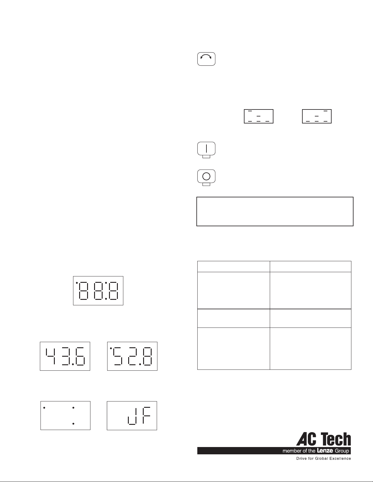
Below are the display symbols used to indicate direction:
FORWARD REVERSE
6. REMOTE KEYPAD FUNCTIONS
e Mkey and the Land Mkeys on the remote keypad function the same as the
Mode button and the Land Mbuttons on the drive. e other remote keypad
functions are described below:
STOP key: Press STOP to Stop the drive. e STOP key is active
whenever the remote keypad is operational.
RUN key: Press RUN to Start the drive. TB-1 must be closed to
TB-11. See the wiring diagram in Section 4
WARNING!
If the remote keypad display is totally blank or only the decimal points are lit, or it
is displaying a “JF” fault, the STOP key WILL NOT stop the drive. e remote
keypad must be operational in order for the STOP key to be active.
5. SETTING UP THE SCL/SCM DRIVE
To set up the SCL/SCM drive to work with the Remote Keypad, the following
parameters must be programmed:
P11 TB-13B FUNCTION Set to REMOTE KEYPAD (13)
P12 TB-13E FUNCTION Set to REMOTE KEYPAD (21)
P14 CONTROL Set to REMOTE KEYPAD ONLY (02).
When this is done, and the Remote Keypad is connected, only the Remote Keypad
can start the drive and select direction. is results in some functions of the drive
being unavailable. ese are explained below:
1. e Dynamic Braking option cannot be used because TB-13E is required for
the Remote Keypad.
2. Settings 05, 06, and 07 on TB-13A (Parameter 10) are disabled. ese settings
are related to direction control. Only the Remote Keypad can be used for
direction commands.
Refer to the SCL/SCM Installation and Operation Manual for more information.
NOTE: Once the drive is set up for Remote Keypad control, the buttons on the
front of the drive are disabled. If they are pressed, the drive display and Remote
Keypad display will show “SE”, indicating that the buttons are disabled.
7. REMOTE KEYPAD DISPLAY
e SCL/SCM Remote Keypad has a three digit display like the SCL/SCM drive.
e displays below are examples of the drive in RUN mode. On the left, the drive is
running at 43.6 Hz. On the right, the speed has been changed to 52.8 Hz (during
speed command changes, the upper left decimal point turns on).
e displays below are examples of problems that will occur if the drive is not properly
programmed or if the keypad is not wired properly to the drive.
Make sure Parameters 11,
12, and 14 are properly
set.
Make sure the keypad is
properly wired to the drive
and the cable is away from
noise.
RUN
RF
STOP
CONDITION / DISPLAY POSSIBLE CAUSES
Remote Keypad display is blank,
or only the decimal points are
illuminated.
Parameter 14 - CONTROL is set to “01”
(TERMINAL STRIP ONLY).
Parameter 11 - TB-13B is not set to “13”.
Parameter 12 - TB-13E is not set to “21”.
e Remote Keypad is not wired
correctly to the drive.
Remote Keypad and/or SCL/SCM
dire dislplays “JF”.
JF indicates a communication problem.
Check for proper wiring between the
remote keypad and the drive.
e R/F key does not work to
change rotation direction.
To use the R/F key to change rotation
direction, Parameter 17 - ROTATION
must be set to “02” (FORWARD AND
REVERSE).
Once the desired rotation direction is
selected, the “M” key must be pressed
within 4 seconds to confirm.