teko ASTRA-863 User manual

Rev. 863-av1_12_en
1
ASTRA-863
Indication unit
User guide
This operating manual is intended to
study the principle of operation, proper
use, storage and maintenance of the
indication unit "Astra-863" version A
(hereinafter referred to as BI) (Pic. 1).
The manufacturer reserves the right to
make changes to the design, firmware,
circuit solutions and product packaging that
do not worsen its technical characteristics,
do not violate mandatory regulatory
requirements, without prior notice to the
consumer.Abbreviations:
IU –indication unit ASTRA-863version A;
Instruction –Instructions built into the
PKM program Astra Pro, Pconf-Pro or
Pconf-RR, or Astra-812 Pro setup instruc-
tions from the keyboard or User instruc-
tions on Wireless extender (available on
the website www.teko.biz);
Buzzer –built-in sound signaling device;;
Control panel –control panel and fire control device "Astra-
8945 Pro" or "Astra-812 Pro";
Wireless extender –radio expander "Astra-RI-M RR" in au-
tonomous mode;
Control device –Control device (Control panel; Wireless ex-
tender);
RS-485 –wired interface Astra-RS-485»;
PKM ASTRA Pro –monitoring firmware package "Astra
Pro" for configuring and monitoring the Control Panel (see on
the website www.teko.biz);
Pconf-Pro - program for configuring Control panel (located on
the website www.teko.biz);
Pconf-RR –computer program "Pconf-RR" for configuring and
monitoring RR (see on the website www.teko.biz);PC –per-
sonal computer;
PO –firmware;
Wireless device –radio channel devices (detectors, relay
blocks, annunciators, etc.) of the Astra-RI-M system
1 FUNCTION
1.1 IU is for:
- receiving notifications from the control device via the wired inter-
face RS-485CONTROL DEVICE,
- displaying the generalized state of the system based on the
CONTROL PANEL or WIRELESS EXTENDER on 8 system
indicators,- displaying the states of CONTROL PANEL logical
partitions or Wireless devices registered in WIRELESS EXTEND-
ER on 38 indicators,
- sound signaling of incoming notifications,
- accepting Touch Memory identifiers from the TM input and trans-
ferring them to the CONTROL PANEL.
1.2 Binding of indicators to partitions or Wireless device is
done from a PC through the program Pconf-Pro, ZL Astra Pro
or Pconf-RR in accordance with the Instructions for CONTROL
DEVICE.
1.3 IU has two independent power inputs (main and backup)
in accordance with GOST R 53325.
1.4 The IU has an input for monitoring the health of external
power sources (terminals ZONE).).
1.5 IU has the ability to connect to the RS-485 CONTROL
PANEL ring interface using Astra-A ILS short circuit isolators.
The IU is powered by external redundant DC sources with a
nominal voltage of 12 V or 24 V.
2 SPECIFICATION
Vltage, V..............................................................from 10 to 27
Average current consumption* at 12 (24) V, mA, .........62 (55)
Increase in current consumption at voltage
power supply 12 (24) V:
- with each additional indicator, not more, mA...................4 (2)
- when the buzzer is turned on, not more, mA ..................2 (3)
Maximum current consumption at 12 (24) V, mA............236(144)
Input ZONE parameters:
Zone terminal voltage in standby mode, V5Short circuit current
at ZONE terminals, mA,
not more ....... 20 Resistanceofwires connected totheZONEinput
(excludingexternalelement), Ohm,nomore220Leakage resistance
between ZONEinput wires
or each wire and"Earth", kOhm, notless than...........................20
ZONE input resistance, kOhm:
- in "Normal" state....................................................from 3 to 5
- in "Violation" state..........................from 0 to 3 or more than 5
ZONE input integration time, ms...................................300±30
OUT parameters:
Maximum load current, mA, not more.................................100
Output voltage, V, not more................................................. 27
RS-485 interface range, m, not more................................1000
TM interface range, m, not more ..........................................25
Overall dimensions, mm, not more....................... 22514523
Weight, kg, not more............................................................0,3
Operating conditions
Temperature range, °С....................................from -10 to + 55
Relative humidity, %....................................до 93 при + 40 °С
without moisture condensation
_______________________
* When using only one partition/Wireless device/valve status indicator
3 DELIVERY SET
IU ASTRA-863version A......................................................1 pc.
Screw...................................................................................3 pc.
Dowel...................................................................................3 pc.
Resistor C1-4-0.25 W 3.9 kOhm ± 5%.................................1 pc.
Manual.............................................................................1 copy.
Sticker..................................................................................2 pc.
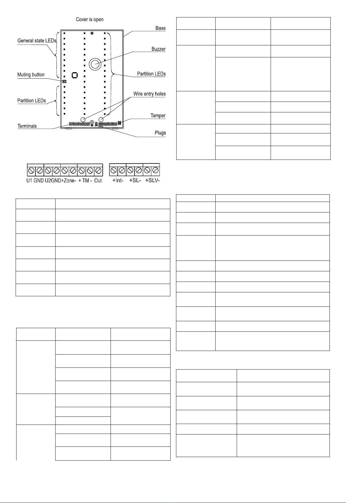
4 DESIGN
4.1 Structurally, the IU is made in the form of a block consist-
ing of a base and a removable cover. A printed circuit board
with radio elements is mounted inside the block (Pic. 2).
4.2 The board has three-color (red-green-yellow) indicators:
-POWER indicator to show IU power status,- 8 indicators for
displaying the generalized current status of all partitions
or Wireless device of the system bound to the IU,
- 38 indicators to display the status of a section/valve or
group of sections when working with the CONTROL PAN-
EL or to show the status of the Wireless device when
working with the WIRELESS EXTENDER.
4.3 Installed on the board: a buzzer for sound notifications
and a mute button.
4.4 The board has an opening button, which, when the cover
is removed, generates a “Tamper” notification, and is also used
to restore factory settings.
Pic. 1

Rev. 863-av1_12_en
2
Pic. 2
4.5 Screw terminals are installed on the board:
Table 1
Terminal
Terminal function
U1, GND
Input for connecting the main power supply
U2, GND
Input for connecting a backup power supply
+Zone-
Control input of the generalized signal "Fault"
of the power supply
+TM-
Input for connecting the TM reader
Out
Output for connecting the TM reader LED
+Int-
Input for RS-485 interface connection
+SL-, +SLV-
Not used
5 NOTIFICATION
Notification when working with CONTROL PANELTable
2 - Notifications to general status indicators
Name
Notification
LED
Power
Power is norm
Solid green
Backup power
1 time green flash per
sec.
Failure
backup power
two times yellow
flashes per sec.
Failure
power
1 time yellow flash
per sec.
Failure
Norm
Solid green
Failure
Solid yellow
Sabotage
Alarm
not used
Не горит
not ready/ready
1 time green flash per
2 sec.
Taken into custody
Solid green
Name
Notification
LED
Violation/Alarm
2 times red flashes
per sec.
Test
Standby mode
is off
Test
4 times green and
yellow flashes during
testing period
Fire danger
not used
is off
norm
is off
attention
1 time red flash per
sec.
Fire
not used
is off
norm
is off
Fire1/
Fire2
solid red
Note –In this version of the system, the indicators START
SYSTEMS, SYSTEMS ON, STOP SYSTEMS are not used and
are off
Table 3 Partition indicator notifications
Notification
LED
Armed
Solid green
Disarmed
1 time green flash every 2 sec
Entry/Exit
Delay
1 time green flash per sec.
No connec-
tion with
Control Pan-
el
All indicators, except for the power indicator,
turn on synchronously in yellow 1 time per
sec.
Fire1
Solid red
Fire2
Solid red
Attention
1 time red flash per sec.
Alarm
2 times red flashes per sec.
Failure
1 time yellow flash per sec.
Sabotage
2 times yellow flashes per sec.
Test
Flashing alternately green and yellow, turn-
ing on 4 times per sec. during the entire test
time
Table 4 - Notifications for partition indicators when working with
a valve
Notification/ Valve
state
LED
Valve in operation
2 times red flashes per sec.
Valve in initial state
Solid green
Failure
valve
1 time yellow flash per sec.
Sabotage
2 times yellow flash per sec.
Switching the valve to
operation / initial state
1 time green flash per sec.

Rev. 863-av1_12
3
Notification/ Valve
state
LED
Required
service
not used
Test
Flashing green and yellow alter-
nately when turning on
4 times / sec during the entire test-
ing time
Table 5 –Buzzer notifications
Notification
Buzzer
Alarm/Violati
on
Sounds continuously for 10 minutes or until
manual shutdown
Fire
Turns on 1 time per sec. until manual shut-
down
Fire danger
Turns on 1 time in 2 sec. until manual shut-
down
Failure
Turns on once every 4 seconds for 10
minutes or until manual shutdown
5.2 Indication with WIRELESS EXTENDER
Table 6 - Notifications for general indicators
Name
Notification
LED
Failure
Norm
Solid green
Radio channel
blocking
Solid yellow
No communica-
tion with Wireless
device or general
fault
1 time yellow flash per
sec.
Opening
2 times yellow flashes
per sec.
Violation
No alarm
Solid green
Violation/ Alarm
2 times red flashes per
sec.
Test
Standby mode
Solid green
Test
Flashing yellow/green
alternately 4 times per
sec. during the entire
time of testing
Attention
Required
service
8 times yellow flashes
per sec.
Service is not
required
Solid green
Fire
Norm
Solid green
Fire
1 time green flash per
sec.
Table 7 - Notifications for single indicators
Notification
LED
Norm
Solid green
Fire
1 time red flash per sec.
Alarm/Violation
2 times red flash per sec.
Test
Flashes yellow and green alternately
4 times per sec. during the entire
testing time
Opening
2 times yellow flashes per sec.
Wireless device
mulfunction
1 time yellow flash per sec.
No connection with
wireless device
Failure
power supply
8 times yellow flashes per sec.
Table 8 –Buzzer notifications
Notification
Buzzer
Alarm
Sounds continuously for 10 minutes or until
manual shutdown
Fire
Turns on 1 time / sec until manual shutdown
Tampering
Turns on once every 4 seconds for 10
minutes or until manual shutdown
6 TEST modes, firmware change and re-
store factory settings
6.1 The IU provides the operating modes "Test at power on",
"Change firmware" and "Restore factory settings".The Power-
On Test mode is designed to check the operation of the IU and
is activated when the IU is powered on. The duration of testing
is no more than 10 sec., while all indicators (except for the
TEST indicator) during the testing time flash at a frequency of 1
time per sec., sequentially changing color: green-red-yellow-
green (the TEST indicator lights up yellow continuously). Buzz-
er in test mode turns on at a frequency of 4 times per sec.
6.2 Firmware update mode
The firmware is changed through the Astra-984 interface de-
vice with a PC using the Firmware Change Module from the
Pconf-Pro, PKM Astra Pro or Pconf-RR firmware pack-
age.Actions order:
1) Switch off the power supply of the IU.
2) Disconnect RS-485 interface wires from IU.
3) Install a jumper in IU on plug F2.
4) Switch on the power supply of the IU.
5) Connect the Astra-984 interface device to the IU, then to
the PC USB port
6) On the PC, launch the Firmware Changer from the Pconf-
Pro firmware package, PKM Astra Pro or Pconf-RR .
7) Select the firmware version for IU from those offered in the
Firmware change module.
8) Write new firmware to the IU, during the firmware change,
the POWER indicator on the IU is red. Wait for the program's
message about the successful recording.
9) Close the program.
10)Switch off the power supply of the IU.
11)Remove jumper from plug F2.
12)Disconnect the Astra-984 interface device from the PC and
IU..
6.3 Restoring factory settings
Performed before re-registration to CONTROL DEVICE or regis-
tration to another CONTROL DEVICE.
Runs with power on.
Sequence of actions (perform within 1 min):
1) close plug F1 for at least 1 second, but no more than 2 sec-
onds;
2) press the opening button and hold it pressed for at least 5,
but not more than 10 sec..
If the factory settings are successfully restored, only one indi-
cator remains on - POWER (see Table 2), the rest of the indi-
cators are off.
7 UNDERWORK PROCEDURE
7.1 IU after transportation in conditions different from operat-
ing conditions, keep unpacked in operating conditions for at
least 4 hours.
7.2 Registering IU in CONTROL PANEL
It is performed through the Configuration Module from the
Astra Pro PKM kit, the Pconf-Pro program, Pconf-RR or
through the Astra-812 Pro CONTROL PANEL menu when the
IU is under its control.
1 Push the base latches out of the grooves of the cover
with a screwdriver, remove the cover
2 Connect IU to CONTROL DEVICE via RS-485 line (see
table 1)
3 Connect power wires to terminals U1, GND and U2,
GND IU. Power on.

Rev. 863-av1_12_en
4
4 Run a program on the PC (Configuration module from the
Astra Pro, Pconf-Pro or Pconf-RR PKM kit) designed to
configure the CONTROL DEVICE with which the IU should
work, or go to the Astra-812 Pro CONTROL PANEL engi-
neer menu. From the program menu or CONTROL PANEL,
start the Register device mode on the CONTROL DEVICE
5Testing:
In case of successful registration, the abbreviated name
“IU” will appear in the program window or on the CONTROL
PANEL screen of Astra-812 Pro.
6At the end of the registration, if it is necessary to store
the IU for a long time before using it at the facility, it is al-
lowed to turn off the power.When the power is turned on, re-
registration in the same CONTROL DEVICE is not required if
the IU has not been forcibly deleted through the program or
using the F1 plug on the IU board (see paragraph 6.3)
8 INSTALLATION
8.1 It is recommended to mount the IU on the wall in a con-
venient place for observation..
8.2 When installing, it is allowed to use mounting devices
(cabinets, boxes, etc.).
8.3 Installation order
1 On the surface chosen for mounting the IU, mark the two
upper holes according to the figure, drill the holes, install
the dowels, tighten the screws
2Push the base latches out of
the grooves of the cover with a
screwdriver, remove the cover
3 Hang the IU on the screwed screws in the place chosen
for installation and mark the bottom hole. Remove IU, drill
hole, install dowel.
4Insert wires through the wire entry holes on the base and
the IU board to connect the power supply (main and back-
up), RS-485 interface, TM, expansion line
5 Hang the IU on the top screwed-in screws in the place
chosen for installation, screw in the bottom fixing screw
fixing the IU to the wall
6 Connect the wires to the screw terminals on the board
7 Close the lid until it clicks
8 Run the PKM program Astra Pro, Pconf-Pro or Pconf-
RR, designed to configure the CONTROL DEVICE with
which the IU should work, and configure the IU in accord-
ance with the Instruction.
The IU indicators are configured from the "System outputs"
menu item of the PKM Astra Pro configuration module or
from the "Indicators and AP" window of the Pconf-Pro pro-
gram.
9 MAINTENANCE
9.1To ensure reliable operation of the alarm system, it is
necessary to carry out IU maintenance at least once every 12
months.
Actions order:
- inspection of the integrity of the IU case, reliability of
fastening, contact connections,
-cleaning the IU case from contamination,
-performance check according to the method of p. 6.1.
9.2 Maintenance of the IU must be carried out by trained
personnel..
9.3 IU repairs are made at the factory.
10 WARRANTY
The operation warranty period is 5 years from the date of opera-
tion start-up, but no longer than 5 years 6 months from the date
of manufacturing subject to the requirements of User guide .
Note!
For detailed information about the product, please refer to the
instruction manual on the website www.teko.biz, which is an
integral part of the operating documentation. This instruction
manual supplied with the product does not contain information
about labelling, compliance with standards, disposal, transpor-
tation and storage.
Manufacturer:
ZAO NTC TEKO
420108, Russia, Kazan,
Gafuri str., 71
Tel.:+7(843) 528-03-69
www.teko.biz
Made in Russia
Popular Measuring Instrument manuals by other brands

Iradion
Iradion Eternity Series Operator's manual

S+S Regeltechnik
S+S Regeltechnik AERASGARD FSFTM-CO2-Modbus Series Operating Instructions, Mounting & Installation

Labgear
Labgear SQ-701 instruction sheet

Hydrion
Hydrion 10 manual

Agilent Technologies
Agilent Technologies G8610A Operation manual

Endress+Hauser
Endress+Hauser Liquiline M CM42 operating instructions