Tekonsha Shur-Set III Guide
Technical Assistance Call Toll-Free: 1-888-785-5832 or www.tekonsha.com
ABCD/Tow Charger/12 Volt Lead-Acid Battery
Instructions and Installation
BREAKAWAY BATTERY CHARGER INSTALLATION
1
12 Volt Sealed Lead-Acid Battery
To maximize the life of the battery the following
conditions should be met:
1. Avoid over or undercharge. This is the
single worst enemy of lead-acid batteries.
2. Batteries should not be stored in
a discharged state or at elevated
ambient temperatures.
3. Avoid exposing batteries to heat!
Service life is shortened considerably
at ambient above 30°C (86°F).
4. Due to the characteristics of this battery,
after six to nine months of storage,
the battery should be recharged.
5. Charge the battery at the proper rate.
Current should be limited to 1.2 amps
or less.
6. Provide adequate air circulation when
charging battery. Do not charge battery
in any other container besides the
supplied battery box.
7. CAUTION Do not place batteries in
close proximity to objects which can
produce sparks or flames.
8. Do not expose battery case to organic
solvents or adhesives.
9. CAUTION Do not attempt to disassem-
ble batteries. Contact with sulfuric acid
may cause harm.
10. CAUTION Fasten batteries tightly and
make provisions for shock absorption if
exposure to shock or vibration is likely.
11. WARNING Do not throw batteries into
fire; batteries so disposed may rupture
or explode.
Battery Data Chart
•12 VOLT
•4amp/hr – max discharge current 20 hr.
rate = 225 mA
•5amp/hr – max discharge current 20 hr. rate
= 250 mA
•Maximum Discharge Current = 40 amps
•Maximum charge current must be limited
to 1.2 amps
•Length = 3.54” Width = 2.76” Height =
4.13”
Weight = 3.8 lbs
Terminals: Fasten Tab .187” x .032”
•Service Life:
Under normal operating conditions, 4-5
years in standby applications or 200-1000
charge/discharge cycles depending upon
depth of discharge and rate of charge.
1. Remove Charger and Battery from
the battery case.
2. Mount battery case securely to
frame, jack post or other suitable
location on trailer.
3. Bolt Breakaway Switch✼to frame
of trailer or battery case bracket.
4. Install battery and charger into the
battery case. Feed wires out the back,
then close the top.
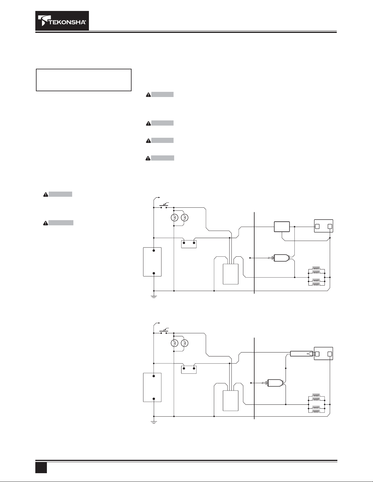
5. Wire per schematic diagram.
Properly insulate all connections.
6. For Technical Assistance and Warranty
Information call: 1-888-785-5832
or www.tekonsha.com
Important Facts to Remember
1. CAUTION Improper installation of the
breakaway battery will destroy the brake
control. The negative (-) terminal must
attach to ground and positive (+) terminal
must attach to the breakaway switch.
2. WARNING Check your Breakaway
System✼periodically to insure that
wiring and connections are secure.
A short or an open circuit can result
in a no-brake condition.
3. If excessive discharging of the
breakaway battery occurs, check
battery and recharge using a Heavy
Duty Two Stage /Maintenance Charger.
If using a commercial (AC to DC)
make certain the 12 volt charge is
limited to 1.2 amps or less.
4. If the secondary battery needs charging,
current will be drawn from the tow vehi-
cle’s battery at anytime the tow vehicle is
connected to the trailer. The most current
which will be drawn is 1.2 amps.
5.
To only charge the breakaway battery when
vehicle is running, a battery isolator may be
installed in the 12 volt supply line (BLACK
wire for tow charger)
.
READ THIS FIRST:
Check condition of battery prior to
installation and prior to each trip.
Tow
Charger
RED
BLACK
RED
BLACK
BLACK
BLACK
BLACK
BLACK
BLACK (+)
BLACK (+) RED (+)
WHITE (–)
BLUE
BLUE
BLUE
BLUE
WHITE WHITE
+12 Volt System
Stop Light Switch
+12 Volt System
Stop Light Switch
+12 Volt
Battery
+12 Volt
Battery
Automatic
Reset
Circuit
Breaker
Automatic
Reset
Circuit
Breaker
+12 Volt
Breakaway
Battery
+12 Volt
Breakaway
Battery
ABCD +
RED
TOW VEHICLE
TRAILER
TOW VEHICLE
TRAILER
Breakaway
Switch✼
Breakaway
Switch✼
–
+
RED
–
+12 V
+12 V
HEAVY DUTY QUICK/MAINTENANCE TWO STAGE CHARGER
ABCD (Accelerated Battery Charging Device)
+
–
+
–
Brake
Control
Brake
Control
TRAILER
BRAKES
TRAILER
BRAKES
BLUE
✼Refer to Breakaway Switch Installation Instructions for complete operating instructions and
cautionary statements.
TOW VEHICLE
CHASSIS GROUND
TOW VEHICLE
CHASSIS GROUND
P/N 2218 REV O 06/03

Installation Guide
1. Mount Battery Case securely to
frame, jack post or other suitable
location on trailer with Breakaway
Switch Cable towards tow vehicle.
2. WARNING Switch location
should be selected to ensure
unobstructed line of pull in
event of vehicle separation.
3. Bolt breakaway switch bracket
to frame of trailer or battery case
bracket using 1/4” bolt and lock nut
or (2) 1/4” jam nuts. (Bolt and nuts
not included in kit.)
4. WARNING Do not over tighten bolt.
Switch must be able to pivot.
5. Check and install battery.
6. Wire per schematic. Properly
insulate all connections.
7. Attaching to tow vehicle: Attach
Breakaway Switch Cable to tow
vehicle frame being certain the
cable does not drag on the ground
and no strain or restriction is placed
on the cable.
8. WARNING Do not hook cable
to safety chain loop or hitch ball.
Technical Assistance Call Toll-Free: 1-888-785-5832 or www.tekonsha.com P/N 2218 REV O 06/03
ABCD/Tow Charger/12 Volt Lead-Acid Battery
Instructions and Installation (Continued)
BREAKAWAY BATTERY CHARGER INSTALLATION
2
+_
TOW VEHICLE
BREAKAWAY SWITCH
ELECTRICAL CONNECTOR
BATTERY
12 VOLT
SPLICE TO BRAKE OUTPUT
FROM TRAILER BRAKES
BRAKE OUTPUT FROM
BRAKE CONTROL
BLUE
BLUE
BLACK
BLACK
BRAKE
OUTPUT
FROM
TRAILER
BRAKES
TOW VEHICLE GROUND GROUND
Important Facts to Remember
1. ATTENTION INSTALLER: Please
give this sheet to consumer upon
completion of installation.
2. SAFETY ITEM: Solder all wire
connections.
3. Check condition of battery prior
to each trip.
4. WARNING Disconnect trailer plug
before testing breakaway unit. Failure
to do so will result in severe damage
to electronic brake control.
5. WARNING Check your breakaway
system periodically to insure that
wiring and connections are secure.
A short or an open circuit can result
in a no-brake condition.
6. For optimal performance, it is
recommended that breakaway
devices be replaced every 3-5 years.
7.
For Technical Assistance and Warranty
Information call: 1-888-785-5832 or
www.tekonsha.com
READ THIS FIRST:
Read and follow all instructions
carefully before installing or operating
the Breakaway Switch. Keep these
instructions for future reference.
BREAKAWAY SWITCH
INSTALLATION INSTRUCTIONS
This manual suits for next models
1


