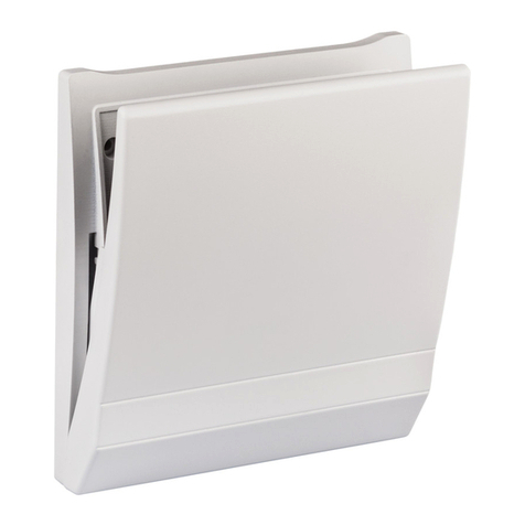
TEKTELIC Communications Gen4 User manual

© 2021 TEKTELIC Communications Inc., all rights reserved.
All products, names, and services are trademarks and registered trademarks of their respective companies.
TEKTELIC Communications Inc.
7657 10th Street NE
Calgary, AB, Canada T2E 8X2
Phone: (403) 338-6900
TEKTELIC Communications Inc.
Smart Room Sensor Gen4
User Guide
Document Type:
User Guide
Document Number:
T0007525_UG
Document Issue:
1.0
Document Status:
Released
Product Name:
Smart Room Sensor Gen4
Product Code & Revision:
T0007496 (CO2 Module)
T0007497 (PIR Module)
T0007498 (CO2 & PIR Module)
Issue Date:
August 17, 2021

Smart Room Sensor (Gen4) User Guide T0007525_UG Version 1.0
TEKTELIC Communications Inc. Page 2 of 18
Revision History
Version
Date
Editor
Comments
1.0
August 17, 2021
T. Danshin,
S. Stewart
Released

Smart Room Sensor (Gen4) User Guide T0007525_UG Version 1.0
TEKTELIC Communications Inc. Page 3 of 18
Table of Contents
Revision History .............................................................................................................................. 2
List of Tables ................................................................................................................................... 4
List of Figures .................................................................................................................................. 5
1Product Description................................................................................................................. 6
1.1 Overview .......................................................................................................................... 6
1.2 Specifications.................................................................................................................... 7
1.2.1 Transducer Details .................................................................................................... 8
1.2.2 Temperature/Humidity Sensor................................................................................. 8
1.2.3 Ambient Light Sensor................................................................................................ 9
1.2.4 Barometer............................................................................................................... 10
1.2.5 CO2Concentration Sensor ...................................................................................... 10
1.2.6 PIR Sensor ............................................................................................................... 10
2Installation............................................................................................................................. 11
2.1 Included Product and Installation Material ................................................................... 11
2.2 Safety Precautions.......................................................................................................... 11
2.3 Unpacking and Inspection.............................................................................................. 11
2.4 Required Equipment for Installation.............................................................................. 11
2.5 Smart Room Sensor Mounting....................................................................................... 11
3Power UP and Commissioning, and Monitoring ................................................................... 13
3.1 Required Equipment ...................................................................................................... 13
3.2 Power Up/Down Procedure........................................................................................... 13
4Operation, Alarms, and Management................................................................................... 14
4.1 Configuration.................................................................................................................. 14
4.2 Default Configuration..................................................................................................... 14
4.3 LED Behaviour ................................................................................................................ 14
4.4 Reset Button Function.................................................................................................... 15
5Compliance Statements......................................................................................................... 16
References .................................................................................................................................... 18

Smart Room Sensor (Gen4) User Guide T0007525_UG Version 1.0
TEKTELIC Communications Inc. Page 4 of 18
List of Tables
Table 1-1: Smart Room Sensor Models.......................................................................................... 6
Table 1-2: Smart Room Sensor Functional Variants ...................................................................... 6
Table 1-3: Smart Room Sensor Specifications ............................................................................... 7

Smart Room Sensor (Gen4) User Guide T0007525_UG Version 1.0
TEKTELIC Communications Inc. Page 5 of 18
List of Figures
Figure 1-1: The Smart Room Sensor models.................................................................................. 6
Figure 1-2: The typical and maximal tolerance for %RH at 25°C................................................... 9
Figure 1-3: The typical and maximal tolerance for the temperature sensor in °C........................ 9

Smart Room Sensor (Gen4) User Guide T0007525_UG Version 1.0
TEKTELIC Communications Inc. Page 6 of 18
1Product Description
1.1 Overview
The Smart Room Sensor is a multi-purpose LoRaWAN IoT sensor packed into a very small form
factor. The Smart Room Sensor is ideal for monitoring and reporting temperature, humidity,
light, barometric pressure, motion, and CO2levels in an indoor environment. Table 1-1 presents
the available Smart Room Sensor models and corresponding LoRa channel plan [1]. Table 1-2
presents the features available in the three functional variants (CO2, PIR, and CO2 & PIR).
Table 1-1: Smart Room Sensor Models
Family
Module T-Code
LoRaWAN RF Region
Tx (Uplink) Band
Rx (Downlink) Band
Smart Room CO2
T0007496
US915
902-915 MHz (ISM)
923-928 MHz (ISM)
Smart Room PIR
T0007497
US915
902-915 MHz (ISM)
923-928 MHz (ISM)
Smart Room CO2 & PIR
T0007498
US915
902-915 MHz (ISM)
923-928 MHz (ISM)
Table 1-2: Smart Room Sensor Functional Variants
Sensing Function
Room Sensor Model
CO2
PIR
CO2 & PIR
Temperature
X
X
X
Relative Humidity
X
X
X
Light
X
X
X
Barometer
X
X
CO2
X
X
PIR
X
X
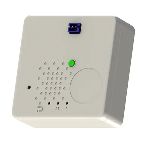
Figure 1-1 illustrates the Smart Room Sensor functional variants. All variants share the same
external dimensions.
CO2 Model PIR & PIR+CO2 Model
Figure 1-1: The Smart Room Sensor models.

Smart Room Sensor (Gen4) User Guide T0007525_UG Version 1.0
TEKTELIC Communications Inc. Page 7 of 18
1.2 Specifications
The Smart Room Sensor specifications are listed in Table 1-3.
Table 1-3: Smart Room Sensor Specifications
Parameter
Requirement
Use environment
Indoor commercial/residential only
Operating temperature
0°C‒60°C
Storage temperature
-40°C‒60°C
RH
5%‒95%, non-condensing
Size
71 mm x 71 mm x 23 mm (enclosure)
71 mm x 71 mm x 26 mm (with bracket assembly)
Weight
91 g (with battery)
Power source
Battery operated, with FET based reverse polarity protection.
Network technology/Frequency band
LoRaWAN with different regional variants (see Error!
Reference source not found.)
Air interface
LoRa
Lifetime
CO2model with baseline use case1transmitting 4 packets per
hour.
•>5.7 years with 2xAA LTC batteries
PIR model with baseline use case transmitting 4 packets per
hour.
•>5.9 years with 2xAA LTC batteries
CO2& PIR model with baseline use case transmitting 4
packets per hour.
•>5.5 years with 2xAA LTC batteries
Maximum transmit power
15 dBm
Number of indicator LEDs
2 (red and green)
Measurement sensing functions
Temperature, humidity, light, pressure, CO2concentration
Detection sensing functions
Human movement
Temperature measurement accuracy
< ±0.3°C between 0°C and 5°C
±0.2°C between 5°C and 60°C
Humidity measurement accuracy
< ±4% between 0% and 100%
±2% between 20% and 80%
1
Baseline use case:
Temperature: 22°C
Tx power: 14 dBm
LoRa SF: 10
LoRa BW: 125 kHz

Smart Room Sensor (Gen4) User Guide T0007525_UG Version 1.0
TEKTELIC Communications Inc. Page 8 of 18
Light sensitivity
Detection of weak light to typical work light conditions (5 lux
to 1000 lux)2
Peak sensitivity at 550 nm
Pressure measurement accuracy
< ±1 hPa between 300 hPA and 1200 hPa
CO2concentration measurement
accuracy
±30 ppm +3% of reading between 400 ppm and 5000 ppm
Extended range ±10% of reading for an extended range of up
to 10000 ppm3
Motion detection
Pyroelectric infrared sensor
Ceiling mount:
•X-angle: 104° (no mask)
•Y-angle: 104° (no mask)
Height: 3 m (no mask)
1.2.1 Transducer Details
1.2.2 Temperature/Humidity Sensor
The Room Sensor includes a combination temperature/humidity transducer from Sensirion
(SHTC3). It is a small footprint, very low power device. It features operation over I2C protocol
and operates from 0% to 100% RH and -40°C to 125°C with a typical accuracy of ±2% RH and
±0.2°C. The typical and maximum accuracies specified across the operating relative humidity
and temperature range of the sensor are shown in Figure 1-2 and Figure 1-3, respectively.
2
The sensor provides light intensity measurements, but they are not calibrated in lux. See the Technical Reference
Manual Invalid source specified. for more details.
3
No data available from manufacturer on performance outside the range of 15°C to 35°C and 0% to 80% RH.

Smart Room Sensor (Gen4) User Guide T0007525_UG Version 1.0
TEKTELIC Communications Inc. Page 9 of 18
Figure 1-2: The typical and maximal tolerance for %RH at 25°C
Figure 1-3: The typical and maximal tolerance for the temperature sensor in °C.
1.2.3 Ambient Light Sensor
A phototransistor and bias resistor form a light detection transducer on the Room Sensor. The
light sensor provides a sufficient window of detection to allow detection of desired light levels.
This window will be tuned as necessary by changing the resistor to give a detection window

Smart Room Sensor (Gen4) User Guide T0007525_UG Version 1.0
TEKTELIC Communications Inc. Page 10 of 18
corresponding to the light levels to be detected. The output of the light transducer is an analog
voltage that is read by the MCU ADC.
Vishay’s TEMT6200FX1 is a phototransistor specifically designed for ambient light sensing as it
includes a filter to give a response similar to the human eye, thus being capable of detecting
weak light to typical work light conditions.
1.2.4 Barometer
A barometer is included in the Room Sensor in order to measure the barometric air pressure.
Infineon’s DPS310 is designed for low power applications while provided highly accurate
measurements. The sensor can operate over a range of 300 hPa to 1200 hPa, and can
communicate over I2C or SPI protocols. The pressure accuracy of the sensor is ±1 hPa between
300 hPa and 1200 hPa while operating between 0°C and 65°C.
1.2.5 CO2Concentration Sensor
The Room Sensor includes the Senseair Sunrise to measure the CO2concentration using non-
dispersive infrared (NDIR). It operates over an I2C interface and can measure in the range of 400
ppm to 5000 ppm with an accuracy of up to ±30 ppm +3% of the reading. This sensor also
features an extended range of up to 10000 ppm with a projected accuracy of extended range
±10% of the reading.
1.2.6 PIR Sensor
A motion detection feature on the Room Sensor is implemented with a PIR sensor. Panasonic’s
EKM1291111 is specifically designed to be sensitive enough to detect small movements with a
wide field of view of 104° x 104°.
The motion detection system uses a ceiling mount type lens that has an expected coverage area
of 7.7 m x 7.7 m when ceiling mounted at a height of 3 m. Note that this is the theoretical
maximum sense range claimed by the transducer manufacturer. The sense range is determined
as the projection of the transducer FoV on the ground, and therefore, should not be interpreted
as the coverage area where the sensor can detect moving people. In general, due to the conical
nature of the transducer FoV, people need to be closer to the sensor to be detected. The
amount of IR radiation from a moving person, which is also impacted by the person’s clothing
or type of skin cover, also plays an important role at determining the detection range.

Smart Room Sensor (Gen4) User Guide T0007525_UG Version 1.0
TEKTELIC Communications Inc. Page 11 of 18
2Installation
2.1 Included Product and Installation Material
The following items are included with each sensor:
•Smart Room Sensor
•Mounting Bracket
•User Guide
2.2 Safety Precautions
The following safety precautions should be observed:
•The Smart Room Sensor is intended for indoor use only.
•The Smart Room Sensor contains lithium batteries.
•NEVER allow small children near batteries: if a battery is swallowed, immediately seek
medical attention.
•To reduce risk of fire, explosion or chemical burns: replace only with approved 2xAA LTC
batteries; DO NOT recharge, disassemble, heat above 100°C (212°F) or incinerate battery.
2.3 Unpacking and Inspection
The following should be considered during the unpacking of a new Smart Room Sensor:
1. Inspect the shipping carton and report any significant damage to TEKTELIC.
2. Unpacking should be conducted in a clean and dry location.
3. Do not discard the shipping box or inserts as they will be required if a unit is returned for
repair or re-configuration.
2.4 Required Equipment for Installation
There are no tools required for Smart Room Sensor installation.
2.5 Smart Room Sensor Mounting
Smart Room Sensor is designed to be mounted using the supplied mounting bracket. The
bracket can be attached using screws or double-sided tape (not included).
When mounting on a vertical surface, ensure that the Room Sensor will not be orientated with
the case retaining screws towards the ceiling. This could cause the Room Sensor to accidently

Smart Room Sensor (Gen4) User Guide T0007525_UG Version 1.0
TEKTELIC Communications Inc. Page 12 of 18
slip off the mount and fall. There are no orientation concerns when the Room Sensor is
mounted to a horizontal surface.

Smart Room Sensor (Gen4) User Guide T0007525_UG Version 1.0
TEKTELIC Communications Inc. Page 13 of 18
3Power UP and Commissioning, and Monitoring
3.1 Required Equipment
No special equipment is required to power on the Smart Room Sensor.
3.2 Power Up/Down Procedure
Once the sensor information has been added to the Network Server, pull out the battery tabs
to engage the battery. To turn off the device the batteries must be removed, but to simply
reset the device, the external reset button can be pushed; see Section 4.4 for description of the
reset function.

Smart Room Sensor (Gen4) User Guide T0007525_UG Version 1.0
TEKTELIC Communications Inc. Page 14 of 18
4Operation, Alarms, and Management
4.1 Configuration
The Smart Room Sensor supports a full range of Over-the-Air (OTA) configuration options.
Specific technical details are available in the Room Sensor Technical Reference Manual [2]. All
configuration commands need to be sent OTA during a sensor’s downlink windows.
4.2 Default Configuration
The default configuration on the Smart Room Sensor is:
•Report Temperature and Humidity every one (1) hour.
•CO2 model only:
oReport the carbon dioxide (CO2) concentration every 15 (fifteen) minutes.
•PIR model only:
oReport motion after 1 (one) PIR event.
oClear motion after 5 (five) minutes of no motion.
•CO2 & PIR model only:
oReport the carbon dioxide (CO2) concentration every 15 (fifteen) minutes.
oReport motion after 1 (one) PIR event.
oClear motion after 5 (five) minutes of no motion.
4.3 LED Behaviour
During the join procedure:
•After the Sensor has gone through the initial boot procedure, the join procedure will
begin. During that time, the red LED will blink continuously until the sensor has joined a
network.
During normal operation:
•The green LED will blink when the Sensor transmits a packet.
•The red LED will blink when the Sensor receives a packet.

Smart Room Sensor (Gen4) User Guide T0007525_UG Version 1.0
TEKTELIC Communications Inc. Page 15 of 18
4.4 Reset Button Function
There is a reset button on the device, that can be pushed by a pin, such as a paper clip. The
button should not be pushed hard. The reset is instant, i.e. the button does not need to be kept
pushed. The reset restarts the microprocessor. All the FW load and configuration parameters in
the Flash are remembered during the reset.

Smart Room Sensor (Gen4) User Guide T0007525_UG Version 1.0
TEKTELIC Communications Inc. Page 16 of 18
5Compliance Statements
Federal Communications Commission
This device complies with Part 15 of the FCC Rules. Operation is subject to the following two
conditions:
1. This device may not cause harmful interference, and
2. This device must accept any interference received, including interference that may
cause undesired operation.
To comply with FCC exposure limits for general population / uncontrolled exposure, this device
should be installed at a distance of 20 cm from all persons and must not be co-located or
operating in conjunction with any other transmitter.
Changes or modifications not expressly approved by the party responsible for compliance could
void the user’s authority to operate the equipment. This equipment has been tested and found
to comply with the limits for a Class B digital device, pursuant to Part 15 of the FCC Rules. These
limits are designed to provide reasonable protection against harmful interference in a
residential installation. This equipment generates uses and can radiate radio frequency energy
and, if not installed and used in accordance with the instructions, may cause harmful
interference to radio communications. However, there is no guarantee that interference will
not occur in a particular installation. If this equipment does cause harmful interference to radio
or television reception, which can be determined by turning the equipment off and on, the user
is encouraged to try to correct the interference by one of the following measures:
•Reorient or relocate the receiving antenna.
•Increase the separation between the equipment and receiver.
•Connect the equipment into an outlet on a circuit different from that to which the
receiver is connected.
•Consult the dealer or an experienced radio/TV technician for help.
Innovation, Science and Economic Development Canada
This device contains licence-exempt transmitter(s)/receiver(s) that comply with Innovation,
Science and Economic Development Canada’s licence-exempt RSS(s). Operation is subject to
the following two conditions:
(1) This device may not cause interference.
(2) This device must accept any interference, including interference that may cause undesired
operation of the device.

Smart Room Sensor (Gen4) User Guide T0007525_UG Version 1.0
TEKTELIC Communications Inc. Page 17 of 18
This device should be installed and operated with minimum distance 0.2 m from human body.
L’émetteur/récepteur exempt de licence contenu dans le présent appareil est conforme aux
CNR d’Innovation, Sciences et Développement économique Canada applicables aux appareils
radio exempts de licence. L’exploitation est autorisée aux deux conditions suivantes:
(1) L’appareil ne doit pas produire de brouillage.
(2) L’appareil doit accepter tout brouillage radioélectrique subi, même si le brouillage est
susceptible d’en compromettre le fonctionnement.
Cet appareil doit être installé et utilise à une distance minimale de 0.2 m du corps humain.

Smart Room Sensor (Gen4) User Guide T0007525_UG Version 1.0
TEKTELIC Communications Inc. Page 18 of 18
References
[1]
LoRa Alliance, "LoRaWAN 1.1 Regional Parameters," ver. 1.1, rev. B, Jan 2018.
[2]
TEKTELIC Communications Inc., "LoRa IoT Smart Room Sensor (Gen4) Technical Reference
Manual," ver 0.1.
Table of contents
Other TEKTELIC Communications Security Sensor manuals

