Operating Instructions--7A19
If the P6201 Probe is used,
a
one megohm input
impedance may be achieved. Consult your local
TEK-
7
RONIX Field Engineer or Representative for further
information.
Vertical Gain Check and Adjustment
To check the gain of the 7A19, set the VOLTSIDIV
switch to 10 mV and connect 20 mV, 1kHz signal from the
oscilloscope Calibrator to the INPUT connector. The
vertical deflection should be exactly two divisions. If not,
adjust the front panel GAIN control for exactly two
vertical divisions.
lnput Coupling
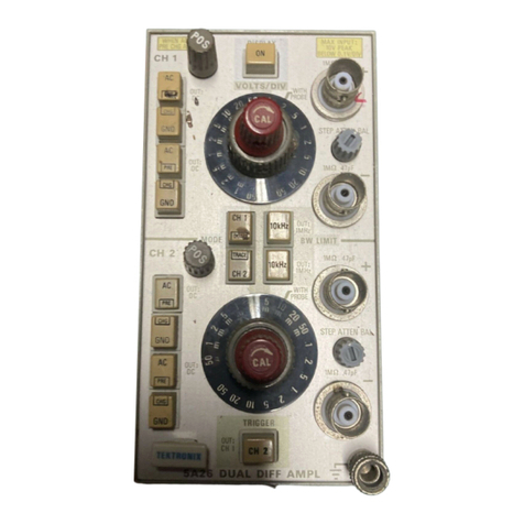
The input coupling switch allows a choice of input
coupling methods. The type of display desired and the
applied signalwill determine the coupling to use.
The DC coupling position can be used for most
applications. For AC signals with frequencies below about
1kHz, and square waves whose low-frequency components
are important to the display, it is necessary to use DC
coupling to obtain asatisfactory presentation.
DC GND position disconnects the signal source from the
amplifier and connects itto a resistive 50 ohm termination,
thus providing the same type of load to the signal source.
The input to the amplifier is also provided with a ground
reference.
In the AC coupling position, the DC component of the
signal is blocked by a capacitor in the input circuit. The AC
coupling position provides the best display of signalswith a
DC component much larger than the AC component.
"Phe PRE-CHG feature should be used when there is a
possibility of having a residual charge on the input
capacitor of the opposite polarity to the intended input,
and when the algebraic sum of the charges may be greater
than the maximum input linlitations of the amplifier. To
use this feature, first set the coupling switch to PRE-CHG,
then connect the signal source to the INPUT and wait
about two seconds for the coupling capacitor to charge, set
the coupling switch to AC.
Another useful feature of the PRE-CHG position is that
it can be used as a calibrated 100X attenuator having an
input impedance of five kilohms in series with two
microfarads. "Phis extends the Low Frequency response to
less than 20 Hz. lnput power should be limited to
118
watt
inthis mode.
The AC GND positiondisconnects the signal source from
the amplifier and connects it to a capacitive coupled 50
ohm termination, thus providing the same type of load to
the signal source. The input to the amplifier is also pro-
vided with a ground reference.
VOLTSIDIV Switch
The amount of deflection produced by a signal is
determined by the signal amplitude, the attenuation factor
of the probe, the setting of the VOLTSIDIV switch, and
the setting of the lnput Coupling switch. Calibrated
deflection factors represented by the VOL 1-SIDIV switch
apply only when the probe attenuation
is
XI
and when the
Input Coupling switch is not inthe PRE-CHGposition (the
PRE-CHG position has an attenuation of 100X).
POLARITY Switch
1
he POLAR1I'Y switch provides a means of inverting the
displayed signal. With the POLARITY switch set to+UP, a
positive-going signal at the INPUT produces an upward
deflection of the CRT display. With the POLARITY switch
set to INVERT, a positive-going signal will produce a
downward deflection of the CRT display.
Trace Identification and Readout Functions
When the IDENTIFY button
is
pressed, the trace is
deflected upward about 0.3 division to identify the 7A19
trace. Phis feature is particularly useful when multiple
traces are displayed on the CRT. In mainframes with
readout, it also replaces the deflection factor readout with
the word "IDENTIFY".
The 7A19 is equipped with probe encoding circuitry
that, when used with acoded probe, corrects the deflection
factor readout.
VARIABLE DELAY (Option
4)
The optional VARIABLE DELAY line provides ameans
for delaying the signal applied to the INPUT for up to+500
DS.
APPLICATIONS
General
The following ~nformationdescribes the proceduresand
techniques for making measurements with
a
7A19 and the
associated rE
K
1"HONIX oscilloscope and time-base. These
applications are not described in detail, since each
application must be adapted to the requirements of the
individual measurements. rhis instrument can also be used
for many applications which are not described in this
Scans by ArtekMedia © 2008
