manuals.online logo
Brands
  1. Home
  2. •
  3. Brands
  4. •
  5. Tektronix
  6. •
  7. Laboratory Equipment
  8. •
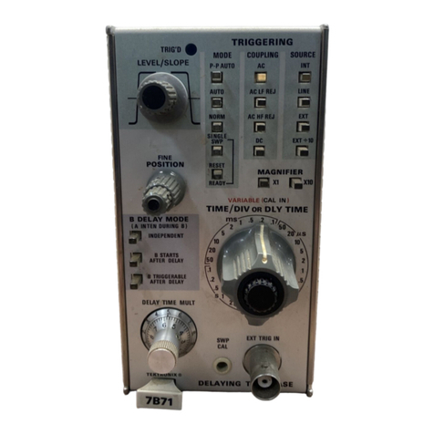
  9. Tektronix 7B71 User manual

Tektronix 7B71 User manual

-

_

_
_~
:
r

-

z
s

r

-
ί
..
ι
.

1

+

_

7

~

.

.
_

.
.

..

.

-

~

.

ι
!"
:_

`1

~

`=
ςΓ
-
Ν

1

λ

_

.
.~
ν
^>
ν

λ
=,
.
εχ
,-
t,

-

F
Y
,~~~
-,

α
-i

J+
.ι
="
.'
νε
~
ς
.

.~,_

_

.
.
,~
~ _,
.
.
:
.

.~
.~~i~~--~~+}-
ξ
, : .
ι

~
._
;~
.11~-i
ι
~xr
. .
.
.~

.r,
._
.~
τ
_
.

.

.,

~
.
_-
τ
^

.>

.
.,
.
.

~

,
._
'1
1
F7"
,

wc
af
ι
i
;
o
i
n
7z'i
-
f-~

,
aronix
monsfarners
pinto,
am
.
i
ul
fKa
inshuxmi
Puy
:
AiwA6
i
-
ιe
dlki'od
"
~
d
to
the
in
your
procedure
will
ass
u
re
you
the
f,osie
5
i
possible
service
.
IfIcase
include
the
niOrun
-
iz-ni
"Iype
and
Soricii
or
Model
Nuin-
ber with
A
recluesis
io,-
ports
or
service
.
)eC
;I'
;ca6ons
(1n(2
price
chonge
privi-
rEmyeed
.
i'
=
,
,
'klrionix,
Inc
. .
ted
in
the
Wited'
COOMMS
OY
A
$
publvatim
may
no
,
he
Oducad
in
un,
Ono
without
'Wands6un
COV
.yrig
Π
i
ownei,
SE
CTIO
N
1
SECTION
2
P
age
S
PECIF
ICATIO
N
S
Introduction
1-1
E
lectrical
C
h
aracteristics
1-1
Swee
pR
ate
1-1
Swee
p
Acc
u
racy
1-1
Swee
p
L
engt
h
1-1
Swee
pH
ol
d
-Off
Time
1-1
V
ariable
-
Time
Delay
1-1
Delay
Time
Accuracy
1-1
M
ulti
p
lier
Incremental
L
inearity
1-1
J
itter
1-1
Differential
Ti
m
e
M
easure
m
ent
Accuracy
1-2
Trigger
Sensitivity
1-2
Internal
Trigger
J
itter
1-2
External
T
rigger
In
p
ut
1-2
L
evel
R
ange
1-2
Ρ
-
Ρ
Auto
Sensitivity
1-2
E
nviron
m
e
n
tal
C
h
aracteristics
Altitude
1-2
Ph
ysical
C
h
aracteristics
F
inis
h
1-2
Dime
n
sions
1-2
W
eig
h
t
1-2
O
P
ERATI
N
G
I
N
STR
U
CTIO
N
S
General
2-1
Installation
2-1
F
ront
P
anel
Controls
2-1
Test
Setu
p
C
h
art
2-4
General
O
p
erating
Infor
m
ation
2-4
Swee
p
Calibration
C
h
ec
k
2-4
Si
m
plified
O
p
erating
Instructions
2-6
Normal
Swee
p
2-6
M
agnifie
d
Swee
p
2-6
Delaye
d
Swee
p
2-6
P
us
h
button
Switc
h L
ogic
2-6
Triggere
d
L
ig
h
t
2-7
Trigger
M
o
d
e
2-7
Trigger
Cou
p
ling
2-9
Trigger
Source
2-10
Trigger
Slo
p
e
2-10
Trigger
L
evel
2-10
H
ori
z
ontal
Swee
p
R
ate
2-12
Swee
p
M
agnifier
2-12
H
ori
z
ontal
P
osition
Control
2-13
Page
SECTION
2
OPERATING
INSTRUCTIONS
(cont)
Applications
2-13
General
2-13
Measurement
Techniques
2-13
Time
Duration
Measurements
2-14
Determining
Frequency
2-15
Risetime
Measurements
2-15
Delay
Sweep
Time
Measurements
2-16
Delayed
Sweep
Magnification
2-17
Displaying
Complex
Signals
Using
Delayed
Sweep
2-18
Pulse
Jitter
Measurements
2-18
SECTION
3CIRCUIT'
DESCRIPTION
Introduction
3-1
Block
Diagram
Description
3-1
Detailed
Circuit
Description
3-1
Trigger
Input
3-1
Input
Source
3-1
Trigger
Amplifier
3-2
General
3-2
External Input
Amplifier
3-2
Input
Stage
3-2
Peak
Detector
3-3
Slope
Comparator
3-3
Output
Stage
3-4
Trigger
Generator 3-4
Trigger
Pulse
Generator
3-4
Sweep
Gate
Stage
3-4
Triggered
Hold-Off
Stage
3-4
Bright
Line
Auto
3-5
Time-Base
Generator
3-5
General
3-5
Normal
Trigger
Mode
Operation
3-5
Single
Sweep
Operation
3-8
Alternate
Operation
3-8
Delayed
Sweep
Operation
3-8
Delay
Pickoff
3-9
Horizontal
Preamp
3-9
Readout
Block
3-9
SECTION
4
MAINTENANCE
Preventive
Maintenance
4-1
General
4-1
Cleaning
4-1
Visual
Inspection
4-1
Transistor
and
Integrated
Circuit
Checks
4-1
Recalibration
4-1
CHANGE
INFORMATION
Abbreviations
and symbols
used
in
this
manual
are
based
on
or
taken
directly
from
IEEE
Standard
260
"Standard
Symbols
for
Units",
MIL
STD-12B
and
other
standards
of
the
electronics
industry
.
Change
information,
if
any,
is
located
at
the
rear
of
this
manual
.
SECTION
4
MAINTENANCE
(cont)
Page
Troubleshooting
4-2
Troubleshooting
Aids
4-2
Troubleshooting
Equipment
4-2
Troubleshooting
Techniques
4-2
Corrective
Maintenance
4-6
General
4-6
Obtaining
Replacement
Parts
4-6
Soldering
Techniques
4-7
Component
Replacement
4-7
Instrument
Repackaging
4-10
SECTION
5
PERFORMANCE
CHECK/CALIBRATION
Introduction
5-1
Test
Equipment
Required
5-1
Short-Form
Procedure
and
Index
5-2
Performance
Check/Calibration
Procedure
5-4
General
5-4
Preliminary
Control
Settings
5-5
Check/Adjust
Steps
(refer
to
Short-Form
Procedure
5-6
for
index
to
steps)
SECTION
6
ELECTRICAL
PARTS
LIST
Abbreviations
and
Symbols
Parts
Ordering
Information
Index
of
Electrical
Parts
List
SECTION
7
DIAGRAMS
AND
MECHANICAL
PARTS
ILLUSTRATIONS
Diagrams
Mechanical
Parts
Illustrations
SECTION
8
MECHANICAL
PARTS
LIST
Mechanical
Parts
List
Information
Index
of
Mechanical
Parts
Illustrations
Mechanical
Parts
List
Accessories
7
Β
71
F
ig
.
1-1
.
7Β
71
Delaying
Time
Base
.
In
tro
d
uction
VA
R
IA
BLE
R
ange
(
u
ncali
b
rate
d
)
5
s/
d
iv
to
0
.1
s
/div an
d
0
.2
μ
s
/d
iv
to
0
.02
μ
s
/d
iv
50
ms/
d
iv
to
0
.5
μ
s/
d
iv
Over
any
2
div
i
n
terval
wit
h
in
center
8
d
iv
Ch
ange
information,
if
any,
affecting
t
h
is
section
will
be
found
at
t
h
e
rear
of t
h
e
man
u
al
.
T
he
71371
Time
Base
U
nit
is
d
esigne
d
specifically
for
use
with
Te
k
tronix
7700-Series
Oscillosco
p
es
.
H
owever,
it
is
com
p
ati
b
le
wit
h
all
7000-Series
Oscillosco
p
es
.
T
he
71371
p
rovi
d
es
cali
b
rate
d swee
p
s
from
5
seco
n
d
s/
d
ivision
to
0
.02
microseco
n
ds/
d
ivision (2
nanosecon
d
s/
d
ivision
with
Χ
10
M
AG
N
I
F
I
ER
)
.
Sweep
r
ates
may
b
e
varie
d
continuously
(
u
ncali
b
rated)
between
calibrate
d
steps
.
Swee
p
triggeri
ng
is
to
200
mega
h
ert
z
or ve
r
tical
a
m
p
lifier
b
an
dwid
th,
w
h
ic
h
-
ever
is
less
.
T
h
e
d
elaying
sweep
feature
of
the
71371,
in
delaye
d
swee
p
operation,
gives
co
n
tin
u
ous sweep d
elay
from
0
to
10
times
the
setting
of the
ΤΙΜΕ
/DI
V
O
R
D
L
Y
5
secon
d
s/
d
ivision
to
0
.02 micro-
seco
n
d
s/
d
ivisio
n
in
α
1-2-5
se-
qu
ence
.
Χ
10
mag
n
ifier
exten
d
s
swee
p
r
ate to 2
n
an
oseco
nd
s/
d
ivision
.
Continuously
varia
b
le
betwee
n
cali-
br
ate
d
sweep
rates
.
Extend
s
uncali-
b
rate
d
sweep
rate
to
at least
12
.5
seco
nd
s/
d
ivision
.
M
easure
d
in
7700
series
mainframe
+15
0
C
to
+35
°
C

0
0
C
to
+50
°
C
U
η
m
αg
Κ
I
_-_
Μ
α
9
_
Γ
._
U
nmag
T
M
ag
_
._
.
3%
ο
TA
BLE
1-1
Electrical
C
ha
r
acteristics
TIME
selector
.
T
h
e
sweep
free-runs
provi
d
ing
αb
rig
h
t
b
ase-
line
in
t
h
e
a
b
se
n
ce of
ade
qu
ate
triggeri
ng
signal
i
nΡ
-
Ρ
A
U
TO
a
nd
AUTO
t
r
iggering
mo
d
es
.
T
h
e
P
erformance
C
h
ec
k
proce
du
re
given
in
Section
5
of
t
h
is
man
u
al
p
rovi
d
es
α
convenient
met
h
od
of
ch
ec
k
ing
p
er-
formance
of
t
h
is
instrument
.
T
h
e
followi
ng
elect
r
ical
ch
aracteristics
apply
at
an
ambient
tem
p
erature
of
0
0
C
to
+50
0
C,
unless
ot
h
erwise
noted
.
W
armu
p
time
for
given
accuracy
is
20
m
inutes
.
Exclude Following
P
ortions
of
Sweep
H
ol
d-Of
f
Ti
m
e
5
s/
d
iv
to
5
μ
s/
d
iv
2
μ
s /
d
iv
to
0
.02
μ
s/
d
iv
Varia
b
le
Time
Delay
Delay
Time
Accuracy
5
s/
d
iv
to
1
s/div

W
ithin
2%
ο
Multi
p
lier
Incremental
L
inearity

W
it
h
in
0
.2%
10
d
ivisions
to
13
divisions
.
s
.
713711
En
d
of
Swee
p
;
b
eyon
d
100
divisions
J
itter

1
1
part
o
r
less
in
50,000
of
10
ti
m
es
t
he
ΤΙΜΕ
/DI
V
setting
Sp
ecification
--7
Β
71
Trigger
Sensitivity
T
ABLE
1-1
(cont)
-------------
Perfor
m
ance
Characteristic
Differential
Time
Measurement
Accuracy
Delay
Time
1
μ
sto0
.5s
1
sto5s
ουριιη
g
AC
AC
LF
REJ
Z
AC
HF
REJ
DC
Single
Sweep
Internal
Trigger
Jitter
W
ithin
1°/
ο
and 2
minor
divisions
W
ithin
2°/
ο
and 2
minor
divisions
Triggering
Fre
q
uency
sweep
only
.
Minimum
Trig-
gering Signal
R
equire
d
__
I
_
NT_
.___
ΓΕΧΤ
___
7575
mV
375
mV
75
mV
375
mV
75
mV
75
mV
375
mV
Triggering
re
quirements
same
as
nor
m
al
swee
p
.
When
triggere
d
,
swee
p
generator
p
rod uces
one
1
n
anosecond
or
less
at
150
mega-
hertz
.
TABLE
1-1
(cont)
_
._
.
.
:
Characteristic

Performance
Input
R
and
C
L
evel
R
ange
(Excluding
Ρ
-
Ρ
AU
TO)
ΕΧΤ
ΕΧΤ
=
10
Ρ
-
Ρ
AUTO
op
eration
Sensitivity
L
ow
Freq
uency
R
es
p
onse
Characteristic
Altitude
1
megohm
within
2%, 20
picofarads
within
2
p
icofara
d
s
.
At
least
+1
.5
volts
to
--1
.5
volts
.
At
least
+15
volts
to --15
volts
.
0
.5
div
Internal,
125
millivolts
E
xternal
200
Hz
to
20
MHz
.
U
pp
er
frequency
an d
am
p
litude limits
same
as
NOR
M
AL
Trigger
Sensi-
tivity
.
M
ust
Trigger
on50
h
ertz,
2
division
signal
.
TABLE
1-2
E
nvironmental
Characteristics
This
instrument
will
meet
the
electrical
characteristics
given
in
Table
1-1
over
the following
environmental
limits
.
E
xternal
Trigger
Input
M
aximu
m
I
nput
500
volts
(DC
+
P
eak
AC)
.
500
Voltage
volts
(P-
Ρ
AC)
at
1
kilohertz
or
less
.
TABLE
1-3
Physical Characteristics
1
On
Internal
Triggering
Only
;
t
he
specifie
du
pp
er
-3
dB
frequency
Finish
Front
panel
is
anodize
d
aluminum
.
of
the
V
ertical
System
replaces
upper
limit
fre
q
uencies
in
t
he
above
table
when
the
number
in
the
table
is
greater
than
the
-3dB
Dimensions
Fits
single
plug-in
com
partment
of
frequency
of
the
Vertical
System
.
7000-series
oscilloscope
.
2
W
ill
not
trigger
on
sine
waves
of
3
divisions
or
less
internal
or
1
.5
volts
external
below
120
Hz
.
W
eight
A
p
proximately
2
.88
poun
d
s
.
General
Installation
General
C
hange
information,
if
any,
affecting
this
section
will
be
found
at
the
rear
of
the
manual
.
The
71371
d
elaying
sweep
p
lug-in
unit
op
erates
with α
Tek
tronix
7000-series
in
d
icator
oscillosco
p
e
and
α
7A-series
vertical
plug-in
un
it
to
form
α
complete
oscillosco
pe
system
.
To
use
t
he
71371
effectively,
its
o
p
eratio
nand
capabilities
sh
oul
d
be
kn
own
.
'T
h
is
section
d
escribes
t
he
ope
r
ation
of
t
he
front-
p
anel
controls,
gives
first-time
and
general
o
p
erati
n
g
information
and
lists
some
basic
a
pp
lica-
tions
for
th
is
i
n
strument
.
The
71371
is
desig
ned
to
op
erate
in
t
he
h
orizontal
p
lug-in
com
p
artments
of
Tektronix
7000-series
oscilloscopes
.
The
71371
can
also
b
e installe
d
in
α
vertical
p
lug-in
com
p
artment
to
p
rovi
d
e
αsweep
t
h
at
ru
n
s
vertically
on
t
he
CRT
.
How-
ever,
w
hen
use
d
in
t
h
is
ma
nn
er,
t
h
ere
is
no
retrace
blan
k
ing
or
i
n
ter
n
al
triggering
p
rovision
an
d
t
he
unit
may
not
meet
t
he
s
p
ecifications
given
in
Section
1 .
The
instructions
in
this
manual
are
writte
n
for
use
of
t
he
71371
in
α
h
orizontal
p
lug-i
n
com
p
artment
of
t
h
e
oscillosco
p
e
.
Wh
en
t
he
71371
is
u
se
dwith
an
oscillosco
pe
w
h
ic
h
h
as
two
h
orizo
n
tal
p
lug-i
n
com
p
artments,
install
t
h
is
unit
i
n
t
h
e
Α
(DE
L
AYI
N
G
TIME
BASE)
compartment
.
Then,
if
a
d
elaye
d
-swee
p
unit
is
installe
d
in
t
he
Β
(rig
h
t)
compart-
me
n
t,
d
elayed-swee
p
o
p
eration
is
available
.
'T
he
71371
will
operate
p
ro
p
erly
in
t
he Β
com
partment
for
all
h
orizo
n
tal
mo
d
es of
operation
excep
t
d
elayi
ng swee
p
.
To
install
the
71371
into
α
p
lug-in
co
m
partment,
push
it
in
u
n
til
it
fits
firmly
i
n
to
t
he
indicator
p
lug-in
com
p
art-
ment
.
To
remove,
pull
t
he
release
latc
h
(see
Fig
.
2-1)
to
dise
n
gage
t
he
unit
from
t
he
i
n
d
icator
and
pull
it
out
of
t
he
p
lug-in
compartment
.
Even
t
h
oug
h
t
h
e
h
orizontal
gai
n
of
t
he
in
d
icator
oscillosco
p
e
is
sta
nd
ar
d
ize
d
to
min
imi
ze
a
d
j
ustme
n
t
w
h
en
i
n
serting
p
lug-in units,
t
he sweep
calib
r
a-
tion of
t
he
71371
sh
oul
dbe c
h
ec
k
ed
w
hen
it is
inserte
d
into
t
h
e
in
d
icator
to
verify
measureme
n
t
accuracy
.
The
pro-
ce
d
ure for
check
ing
the
unit
is
given
und
er
Swee
p
Cali
b
ra-
tion
C
h
eck
in
t
h
is
section
.
FRONT-PANEL
CONTROLS
All
controls
requi
r
e
d
for
t
he
o
pe
r
ation
of
the
71371
are
locate
d
on
t
he
front
p
anel of
t
he u
n
it
(see
Fig
.
2-2)
.
To
Α
F
ig
.
2-1
.
Locatio
n
of
release
latc
h
.
ma
ke
full
use
of
t
he
ca
p
abilities
of
t
h
is
i
n
stru
m
e
n
t,
t
he
o
pe
r
ator
s
h
oul
d
be
familiar
wit
h
t
he
fu
n
ctio
n
an
d
use
of
each
of
t
h
ese
con
trols
.
Α
b
r
ief
descri
p
tion
of
t
h
e
fro
n
t-
p
anel
con
trols
an
d
con
n
ector
is
give
n
h
ere
.
More
d
etailed
informatio
n
is
given
under
Ge
n
eral
O
p
erating
Information
.
Triggering
Controls
713711
LEVEL
IS
L
O
PE

Selects
t
he
amplitu
de
p
oi
n
t
a
nd
slope
of
trigge
r
signal
on
w
h
ic
h
t
he
sweep
is
triggere
d
.
Wh
en
t
he
in
d
ica
tor
line
on
t
he
outer
ring
is
to
t
he
left
of
center,
t
he sweep
is
triggere
d
on
t
he
positive-going
slo
pe of
t
he
trigger signal,
as
s
h
own
by
t
he
p
ositive-going
waveform
.
To
t
he
rig
ht
of
center,
t
he
swee
p
is
trig-
gere
d
on
t
he
negative-goi
ng
slo
pe
of
t
he
trigger
signal as
s
h
own
b
y
t
he
n
egative-going
waveform
.
ΤR
IG'D

L
ig
h
t
in
d
icates
t
h
at
t
he sweep
is
triggere
d and
will
produce
α
display
with co
r
rect setting
of
t
he
POSI
TION
con
trol
and
t
he
controls
on
t
he
associated ve
r
tical
unit
an
d
i
nd
i-
cator
oscillosco
p
e
.
Ope
r
ati
ng
Instructions-713711
TR
IGG
ER
I
NG
TR
IG'D
"

MODE

CO
UPL
I
NG
LEVEL
/S
L
OPE
Ρ
-
Ρ
AUTO
AC
ι
r
ιτ
ιη
~ ;
ιπι
., ,
CA
L
IN
Ι
,
ΧΙΜΕ
/DI
V
O
R
D
L
Y
TIME
εΙ

ms
'5
.2
7_
~lj
2
T
RIGG
ER
CO
N
T
RO
LS
S
WEEP
CO
N
T
RO
LS
T
RIGG
ER
CO
N
T
RO
L
M
OD
E
2-2
Se
r
ies
of
push-button
switc
h
es to
select
t
he
trigge
r
m
ode
.
Selecte
d
mo
d
e
is
i
nd
icated
by
lig
h
te
d
b
utto
n
.
Ρ
-
Ρ
AU
TO
:
Swee
p
automatically
t
r
igge
r
ed
at
p
oint
selecte
d
b
y
t
he
LEVEL/SLOPE
control
w
hen
the
tr
igge
r
signal
re
p
etitio
n
r
ate
is
a
b
ove a
b
out
200
h
e
r
tz
a
nd
wit
h
i
n
t
he
freq
uency
ra
n
ge
Fig
.
2-2
.
Fr
o
n
t-
P
an
el
co
n
trols
and
co
nn
ectors
.
selecte
d by
t
h
e
CO
UPL
I
NG
switc
h
.
T
r
igge
r
ed
sweep
can
b
e
o
b
tai
ned
t
hroug
h
out
t
he
r
an
ge
of
t
h
e
LEVEL
/S
L
O
PE
control
.
Wh
en
t
h
e
t
r
igge
r r
ep
etition
r
ate
is
b
elow
t
he
lowe
r
freq
u
e
ncy
li
m
it
(o
r
above
upp
e
r
limit
fo
r
AC
HF
REJ)
o
r
w
hen
t
he
tr
igger
sig
n
al is
i
nade
q
uate,
the
swee
p
f
r
ee
r
uns
at
the
swee
p
r
ate
selecte
d b y
t
he
ΤΙΜΕ
/DI
V
switc
h
to
pr
oduce
α
r
efere
nce
tr
ace
.
A
U
TO
:
Swee
p
i
n
itiate
d
by
t
h
e
app
lied
trigge
r
signal at
p
oi
n
t
selecte
d
b
y
t
h
e
LEVEL
/S
L
O
PE
co
n
trol
w
h
e
n
t
h
e
trigger
sig
n
al
re
p
etitio
n
rate
is
above
abo
u
t
30
h
ertz
a
n
d
wit
h
in
t
h
e
fre
q
u
ency
range
selecte
d
by
t
h
e
CO
U
-
PL
I
N
G
switc
h
.
Triggere
d
sweep
can be
obtai
ned only
ove
r t
he
am
p
lit
ud
e
range
of
t
he app
lie
d
trigger
signal
.
Wh
en the
LEVEL
/
SL
O
PE co
n
trol
is
outsi
de the
am
p
lit
ude
r
an
ge,
t
he
t r
igge
r
re
p
etition
rate
is
b
elow
t
he
lower
fre
q
uency
limit
(or
above
up
p
er
limit
for
ACHF
REJ)
or
t
he t
r
igger
sig
n
al is
inade
q
uate,
t
he
swee
p
free
r
uns
at
t
he sweep
r
ate
selecte
d
by
t
he
ΤΙΜΕ
/DI
V
switc
h
to
p
ro
duce
α
refere
n
ce
trace
.
NORM
:
Swee
p
i
n
itiate
dby
t
he
a
pp
lie
d
trigger
signal
at
any
p
oint
selecte
dby
t
he
LEVEL
/
S
L
O
PE
control
over
t h
e
fre-
q
uency
r
an
ge
selecte
db
y
t
he
CO
UPL
I
NG
switc
h
.
Trigge
r
ed
swee
pcan
b
e
obtaine
d
only
over
t
he
am
p
litu
d
e
range
of
t
he
a
pp
lied
trigger
signal
.
Wh
en
t
h
e
LEVEL
/S
L
O
PE
con
trol
is
out-
si
d
e
t
he
am
p
litu
d
e
range,
t
h
e
trigger
re
p
etition rate
is
outsi
d
e
the
fr
e
q
uency
range
selected
b
y
the
CO
UPL
I
N
G
switc
h
or
the
t r
igger
signal
is
ina
de
q
uate,
t
h
ere
is
no
trace
.
SI
NG
LE
S
WP
:
Swee
p
i
n
itiate
d
by
t
he
a
pp
lie
d
trigger
signal
at
any
p
oi
nt
selecte
dby
t
he
LEVEL
/
SL
O
PE
control
over
the
fre-
q
uency
range
selecte
d
by
t
he
CO
UPL
I
NG
switc
h
.
Triggere
d
swee
pcan
be
o
b
taine
donly
over
t
he
am
p
litu
d
e
range
of
a
p
p
lie
d
trigger
signal
.
After
t
h
e
first
sweep
is
d
is
p
laye
d
,
furt
h
er
swee
p
s cannot bep
r
ese
n
te
du
n
til
the
RESE
T-
RE
ADY
p
us
h
-
b
utton
is
presse
d
.
Wh
en
t
he
LEVEL
/S
L
O
PE
control
is
out-
si
d
e t
he
am
p
litu
d
e
ra
n
ge,
t
he
trigger
r
ep
etition
rate
is
outsi
de
t
he
fr
equency
range
selecte
d
by
t
he
CO
UPL
I
NG
switc
h
,
the
trig-
ger
sig
n
al
is
ina
d
eq
uate
or
w
h
en
t
he
RE
SET"-RE
ADY
lig
h
t
is
off,
t
h
ere
is
no
t r
ace
.
CO
UPL
I
N
G
SOUR
C
E
Op
e
r
ating
Instructions---71371
RE
S
E
T-
R
EADY
:
P
us
h
-butto
n
to
reset
t
h
e
Swee
p
Ge
n
erator
for
th
e
next
sweep
in t
h
e
single-
swee
p
mo
d
e
.
T
h
e
RESET-
READYbutto
n
remains
lig
h
te
d
to
i
n
dicate
t
h
at
t
h
eu
n
it is
r
eady
to
b
e
triggere
d
.
Afte
r
t
h
e unit
is
triggere
d
an
d
α
sweep
is
com-
p
leted,
t
he
RESET-READY
lig
h
t
goes
out
until
t
he
button
is
p
resse
d
agai
n
.
Series
of
p
us
h
-button
switc
h
es
to
select
t
he
trigger
cou
p
ling
.
Selected
coup
li
ng
is in
d
icate
d
b
y
lig
h
te
d
b
utto
n
.
AC
:
R
e
j
ects
DC
an
d
attenuates
AC
sig
n
als
below
a
b
out
30
h
ertz
.
Acce
p
ts
sig
n
als
between
30
h
ertz
and
200
mega
h
ertz
.
AC

LF

REJ
:
R
e
j
ects

DC

an
d
attenuates
signals
below
ab
o
u
t
30
k
ilo
h
ertz
.
Acce
p
ts
sig
n
als
b
etween
30 k
ilo
he
r
tz
an
d
200
mega
h
ertz
.
AC HF
R
EJ
:
Acce
p
ts
signals
be-
tween
about
30
h
ertz
an
d
50
k
ilo
h
ert
z
.
R
ejects
DC
an
d
atte
n
-
uates
sig
n
als
outsi
d
e
t
h
is
fre-
q
ue
n
cy
range
.
DC
:
Accepts
all
trigger
signals
from
DC
to
200
mega
h
ertz
.
Series
of
push
-button
switc
h
es
to
select
t
he
trigger
source
.
Selecte
d
so urce
is
in
d
icate
d
b
y
lig
h
te
d
button
.
ΙΝΤ
:
Trigger
signal
obtained
inter-
nally
from
α
vertical
unit
.
L
I
N
E
:
Trigger
signal
obtai
ned
internally
from
α
sam
p
le
of
t
h
e
line
voltage
a
pp
lie
d
to
t
h
is
instrument
.
ΕΧΤ
:
Trigge
r
sig
n
al
obtaine
d
from
an
external
signal
app
lie
d
to
t
h
e
ΕΧΤ
TRIG
IN
con
n
ector
.
ΕΧΤ
-~
10
:
Trigger
signal
obtai
ned
from
an
exter
n
al
signal
a
pp
lied
to
t
he
ΕΧΤ
TRIG
IN
connector
as
in
t
he
ΕΧΤ
p
osition
.
In
t
h
is
2-
3
O
pe
r
ati
ng
I
n
structions--71371
ΕΧΤ
TRIG
IN
Swee
p
Co
n
trols
P
OSITIO
N
Controls
h
orizo
n
tal
p
osition
of
d
isplay
.
FINE
ΤΙΜΕ
/DI
VO
R
DL
Y
TIME
VAR
IA
BLE
M
AG
N
I
F
I
ER
2-
4
p
ositio
n
t
he
exter
n
al
signal
is
atte
nu
ate
d10
times
befo
r
e
it
is
a
pp
lie
d
to
t
h
e
t r
igger
circuit
.
In
p
ut
con
nector for
external
trigger
signal
.
Pr
ovi
d
es
more
p
recise
co
n
trol
of
h
orizontal
p
ositions
.
Selects
the
basic
sweep
rate
of
t
he
out
p
u
t
sawtoot
h
a
nd
selects
basic
d
elay
ti
m
e
(to
be
multi
p
lie
d
b
y
t
he
D
EL
AY
TIME
MUL
T
dial
setting)
.
T
he
V
A
R
IA
BLE
control
must
be
in
calibrate
d
positio
n
and
M
AG
N
I-
F
I
E
D
switc
h
set
to
Χ
1
for
in
d
icate
d
swee
p
rate
.
Two-position
switc
h
actuate
d
by
t
he
VA
RIA
BLE
kn
ob
to
select
cali-
brate
d
or
un
calib
r
ate
d
swee
p
r
ates
.
At
t
he
in
p
osition,
t
he
V
A
R
IA
BLE
control
is
ino
p
erative
and
t
he
swee
p
rate
is
calibrate
d
.
Wh
en
p
resse
d
an
d
release
d
,
t
h
e
kn
ob
moves
out to
activate
t
h
e
VA
R
IA
BLE
control
for
uncalib
r
ated
swee
p
rates
.
The
swee
p
rate
in
each
ΤΙΜΕ
/DI
V
switc
h p
osition
ca
n be
re
d
uce
d
to
at
least
t
h
e
sweep
rate
of the next
a
d
j
acent
position,
to
p
r
ovi
de
con-
tinuously
variable
sweep
rates
fro
m
2
nanoseco
nd
s/
d
ivision
(X10-
MAGNIFIER
on)
to
about
12
.5
secon
d
s/division,
with
M
AG
N
I-
F
I
ER
at
Χ
1
.
P
ush
-button
switc
h
es
to
select
t
h
e
h
orizo
n
tal
mag
n
ification
.
T
h
e
Selecte
d
magnification
is
in
d
icate
d
by
α
lig
h
te
d
button
.
Χ
1
:
M
agnifie
d
swee
p
at
t
he
b
asic
sweep
rate
i
n
d
icate
dby
TIME/
DI
V
switc
h
.
Χ
10
:
M
ag
n
ifie
d
swee
p
at
α
swee
p
rate
10
ti
m
es
faster
t
han
t
he
b
asic
swee
p
r
ate
in
d
icate
dby
t
he
ΤΙΜΕ
/DI
V
switc
h
.
T
h
e
p
ortio
n
of the normal
sweep
with
in
t
he
ce
n
ter
d
ivisio
n of
t
he
graticule
is
t
he
p
ortio
n sh
own
in
magnifie
d
form
.
S
WP
CA
L
Screw
d
river

ad
j
ust
m
ent
to
set
amplitu
de
of
t
he outp
ut
sawtooth
.
Delay
Controls
Β
D
EL
AY
M
OD
E
Series
of
p
u
sh
-button
switc
h
es to
(
Α
ΙΝΤΕΝ

select
t
he
d
elay
logic
to
t
he
com
D
UR
I
NG
Β
)

p
anion
delaye
d
-swee
p
unit
(
Β
)
.
Selecte
d
d
elay
mo
de
is in
d
icate
d
by
α
lig
h
te
d b
utton
.
General
Swee
p
Calibration
C
h
ec
k
INDEPENDENT
:
T
he
71371
and
t
he
com
p
an
ion
d
elaye
d
-swee
p
unit
(
Β
)
o
p
erate
i
nde
p
end
ently
as
normal
time-base
units
.
Β
STA
R
TS
A
F
TER
D
EL
AY
:
T
he
com
pan
ion
d
elayed-swee
p
unit
(
Β
)
p
ro
d
uces
αsweep
immediate-
ly
following
t
he
d
elay
time
selecte
d
by
t
he
ΤΙΜΕ
/DI
VO
R
D
L
Y
TIME
switc
h an
d
t
he
D
EL
AY
TIME
MUL
T
d
ial
.
Β
TRIGG
ER
A
BLE
A
FT
ER
D
EL
AY
:
T
he
com
p
anion
d
elaye
d
-
sweep
unit
(
Β
)
pro
d
u
ces
αsweep
after
t
he
first
trigger
p
ulse
is
receive
d
followi
ng
t
he d
elay
time
selected
b
y
t
he
ΤΙΜΕ
/DI
V
O
R
D
L
Y
TIME
switc
han
d
t
h
e
DELAY
TIME
MUL
T
DIA
L
.
D
EL
AY
TIME
MUL
T

P
rovides
varia
b
le

delay
fo
r
t
he
delay
p
ulse
to
t
he
com
p
anion
d
elaye
d
-swee
p
u
n
it
(
Β
)
from
0
to
10
times
t h
e
basic
delay
time
selec-
te
d
b
y
t
h
e
ΤΙΜΕ
/DI
V
O
R
D
EL
AY
TIME
switc
h
.
'TEST
S
E
TU
P
C
H
A
RT
F
ig
.
2-3
s
h
ows
t
he
front panel
of
t
h
e
71371
.
T
h
is
ch
art
ca
n be
re
pr
od
uced and
use
d
as
α
test-setu
p
recor
d
for
sp
ecial
measureme
n
ts,
app
licatio
n
s
or
proce
d
ures,
or
it
may
be
use
d
as
α
trai
n
ing
ai
d
for
familia
r
ization
with
t
h
is
instr
u
ment
.
G
E
NER
A
L
OPERATING
INF
O
RM
ATION
W
he
n
ever
t
h
e
71371
is
inserted into
α
p
lug-in
com
p
art-
m
ent oth
er
t
h
a
n
t
he one
in
w
h
ic
h
it
was
calibrated,
t
he
sweep
calib
r
ation
s
h
ould
b
e ch
ec
ke
d
and
r
ead
j
uste
d
if
F
ig
.
2-3
.
7Β
71
Test
Set
up
C
h
art
.
O
p
erating
Instructions-7B71
2-5
O
p
erating
Instructions

71371
n
ecessary
.
Allow
five
m
i
n
utes
warmu
p
before
performing
t
h
is
proce
d
ure
.
1
.
Connect
αone-k
ilo
h
ertz
calibrator
signal
from
the
In
d
icator
Oscillosco
p
e
Cali
b
rator
to
t
he
V
ertical
unit
in
p
ut
conn
ector
.
2
.
Set
t
h
e
ΤΙΜΕ
/DI
V
switc
h
to
1
ms
an
d p
ress
t
he
to
p
T
R
IGG
ER
I
NG
and
Β
D
EL
AY
M
OD
E
pu
s
hb
utto
n
s
.
3
.
Set
t
he
V
ertical
unit to
d
isplay
at
least
two
divisions
of
t
he
signal
vertically
.
4
.
C
h
ec
k
t
he
CR
T
d
is
p
lay
for
one
co
m
plete
cycle
p
er
d
ivisio
n
.
5
.
If
necessary,
ad
j
ust
t
he
S
WP
CA
L
a
d
ju
stment
for
one
com
p
lete
cycle
per
division
.
Si
m
plifie
d
O
p
erating Instructions
T
he
following information
is
p
rovi
d
e
d
to
ai
d
in
q
uic
k
ly
obtaining
t
he
correct
settings
for
t
he
71371
to
p
resent
α
display
.
T
he o
p
erato
r s
h
oul
d
be
familiar
with
t
he
com
p
lete
functio
n an
d
o
pe
r
ation
of
t
he
unit
as
d
escribe
d
in this
section
before
usi
ng
t
h
is
p
roce
d
ure
.
Normal
Swee
p
.
T
he
followi
ng
p
roce
dure
will
provide
a
stable
d
isplay
for
most
n
ormal-sweep
a
pp
lications
.
1
.
Select
the
TRIGG
ER
I
N
G
M
ODE,
CO
UPL
I
N
G
an
d
SOUR
C
E
w
h
ic
h
fit
t
he
r
e
q
ui
r
ements
of
t
h
e
signal
to
be
d
isplaye
d
.
2
.
Tu
rn
t
h
e
LEVEL
/SL
O
PE
control
to
t
he d
esire
d
slo
pe
.
3
.
If
the
green
'TRIG"D
lig
h
t
is
n
ot
on, a
dj
ust
the
'LEV
EL
/S
L
O
PE
control
t
hr
oug
h
out
the
ra
nge
of
t
he
selec-
te
d
slo
p
e
until
t
he
TRIG"D
lig
h
t
comes
on
.
If
the
lig
ht
d
oes
n
ot
come
on
at
any
setti
ng
of
t
he
LEVEL
/S
L
O
PE
control,
t
he
tr
igger
sig
n
al is
i
n
a
de
q
uate or
t
he
CO
U
PL
I
N
G
and
SO
UR
CE
switc
h
es
are
set
i
n
correctly
.
4
.
Set the
ΤΙΜΕ
/DI
V
switc
h
and
P
OSITIO
N
control
for
αd
isplay
w
h
ic
h remains
on
t
he
d
is
p
lay
area
h
orizontally
(V
A
R
IA
BLE
control
s
h
oul
dbe
in
CA
Lp
osition
for
cali-
b
rate
d
swee
p
rates)
.
5
.
If
t
he
d
is
p
lay
d
oes not
start
at
t
he
correct
point
on
.t
he
waveform,
rea
d
j
ust
t
he L
E
VEL
/S
L
O
PE
control
for
t
h
e
d
esire
d
triggeri
n
g
.
2-6
M
agnifie
d
Swee
p
.
Α
magnifie
d
-swee
p
d
is
p
lay
can
b
e
ob
tained
as
follows
after
αn
ormal-swee
p
d
is
p
lay
is
obtaine
d
as
given
in
steps
1-5
above
.
1
.
A
d
j
ust
t
h
e
P
OSITIO
N
control
to
move
t
h
e
area to be
m
agn
ifie
d
wit
h
in
t
he
ce
n
ter
d
ivision
of
t
he
C
R
T
.
2
.
If
necessary,
change
t
he
ΤΙΜΕ
/DI
V
switc
h
setting
so
the co
m
plete
area to be
magnified
is
with
in
t
he
center
d
ivi-
sio
n
.
3
.
P
ress
t
he
X10-MAGNIFIER
pus
h
-butto
n
.
4
.
U
se
t
he
fi
ne
range
of
t
he
P
OSITIO
N
control
to
establis
h
precise
p
ositio
n
ing
of
t
h
e
m
agnifie
d d
isplay
.
Delaye
d
Swee
p
.
T
he
followi
n
g
p
rocedure
can
b
e
use
d
to
o
b
tain
αd
elaye
d
-swee
p
dis
p
lay
w
hen
t
he
71371
is
use
d
in
an
oscillosco
p
e
t
h
at
h
as
d
ual
time
base
ca
p
abilities
and
w
h
en
use
d
wit
hα
compa
n
ion
d
elaye
d
-swee
p
unit
(
Β
)
.
Obtain
α
d
is
p
lay
as
give
n
in
ste
p
s
1-5
un
d
er
Normal
Swee
p
.
Then
procee
d
as
follows
:
1 .
Pr
ess
t
h
e
Β
STA
R
TS
A
F
TE
R
D
EL
AY
push
-button
.
2
.
Set
t
he
i
n
d
icator
oscillosco
pe
h
orizontal
mo
de
to
dis-
play
the
Α
time
base
(71371)
.
3
.
Set
the
time/
d
ivision
switc
h of
t h
e
com
p
a
n
ion
d
elaye
d
-swee
p
unit
(
Β
)
so
t
he
inte
n
sifie
d
zone
on
t h
e
dis-
play
is
t
he d
esired
lengt
h
(i
n
tensified
zone
will
bed
is
p
laye
d
in
d
elayed
form)
.
If
t
he
intensified
zone
is
not
visible,
a
dj
ust
t
he
in
d
icato
r
i
n
te
n
sity
controls
.
4
.
Ad
j
ust
t
he
D
EL
AY
TIMEMUL"
Τ`
d
ial
to
p
osition
t
he
i
n
te
n
sified
zone
to
t
he
portio
n
of
t
he
d
is
p
lay
to be
d
elayed
.
5
.
Set
t
he
in
d
icato
r
oscillosco
p
e h
ori
z
ontal
mo
de
to
dis-
play
t
h
e
Β
time
base
(
d
elaye
d
swee
p
u
n
it)
.
6
.

If
αd
elaye
d
sweepwith
less
j
itter
is
desire
d
,
p
ress
t
he
71371
Β
TRIGG
ER
A
BLE
A
F
TE
R D
EL
AY
p
us
h
-b
u
tto
n
.
T
he
triggering
controls
of
t h e
com
p
anio
n d
elayed-sweep
u
nit
(
Β
)
m
u
st
be
set
to
obtain
α
stable
d
is
p
lay
.
See
t
he
instr
u
ction
manual
for
that unit
for
furt
h
er
information
.
P
us
h
butto
n
Switc
h L
ogic
T
he
'TRIGG
ER
I
N
G
M
OD
E
,
CO
UPL
I
NG
and
SOUR
C
E
switc
h
es an
d
t
he Β
DE
L
AY
M
OD
E
switch
are
arrange
d
in
α
sequence
w
h
ic
h p
laces
th
e
m
ostoften-used
positio
nat the
top
of
eac
h
series
of
p
us
h
buttons
.
W
it
h
t
h
is
ar
r a
n
gement,
α
stable
d
is
p
lay
can
usually
be o
b
taine
d by
p
r
essing
t
he
to
p
p
us
h
-b
u
tto
ns
;
Ρ
-
Ρ
AU
TO, AC, ΙΝΤ
a
n
d
I
N
DEPE
N
D
EN
T
.
Wh
en an
a
d
eq
uate
t
r
igger
signal
is
app
lied,
t
he
unit
is
trig-
gere
d
as
i
n
dicate
d by
t
he
illumi
n
ated
TRIG'D
lig
h
t
at
any
setting
of
the
LEVEL
/S
L
O
P
E
control
.
If
t
h
e
T
R
IG'D
lig
h
t
is
n
ot
on,
eit
h
er
t
he
trigger
signal
a
p
plie
d
to
t
h
is
unit
from
t
h
e
vertical
u
n
it
is
i
na
d
eq
uate
or
it is
below
t
he lower
fr
e-
quency
limit
of
t
he
ACCO
UPL
I
NG
switc
hp
osition
.
If
the
d
esire
d d
is
p
lay
is
not
o
b
tained wit
h
t
he pu
s
hb
utto
n
s
p
us
he
d
in,
ot
h
er
selections
must
be
ma
d
e
.
Refer
to
t
he
following
d
iscussions
or
t
he
instruction
manuals
for
t
he
associate
d
in
d
icator
oscilloscope
an
d
vertical
unit
for
more
informatio
n
.
T
riggere
d
L
ig
h
t
The
7RIG'D
lig
h
t
pr ovides
α
convenient
in
d
ication
of
t
h
e
con
ditio
n
of
t
he
triggeri
ng
circuits
.
If
t
he
T
R
IGG
ER
I
N
G
controls
a
r
e
correctly
set
an
d
an adeq
uate
trigge
r
signal
is
ap
plie
d
,
t
he
ΤR
IG'D
lig
ht
is
on
.
Un
d
er
certain
con
d
itions,
t
he
TRIG'D
lig
h
t
may
be
off, in
d
icating
t
h
at
t
he
swee
p
is
n
ot
triggere
d
.
T
he
cause
migh
t
be
α
misa
d
j
uste
d
LEV
EL/
SL
O
PE
control,
i
n
correctly
set
CO
UPL
I
N
G
or
SO
UR
C
E
switc
h
es,
low
t r
igge
r
signal
am
p
litu
d
e,
o
r
α
trigger
sig
n
al
re
p
etitio
n
r
ate
outsi
de
t
heaccep
table
f r
equency
range
.
T
h
is
feature
can be
use
d
as
α
general
in
d
ication
of
correct
trig-
ge
r
ing
.
It is
p
a r
ticularly
useful
w
h
en
setti
ng up
t
he
trigger
circuits
w
hen α
trigger
signal
is
available
wit
hout α
d
is
p
lay
on the
CRT
.
It
also
in
d
icates
th
at
t
h
is
u
n
it
is
co
r
rectly
tr
iggere
d
w
h
en
op
erating
as
α
delayi
n
g-swee
p
unit
(
Α
) .
α
:
ι
c
ιν
υυαι
rιcα
;
INN
.-
,-_
+
p
r
ε
»
ιι
Fig
.
2-4
.
View
of
fro
n t
panel
s
h
owi
ng
pu
s
h-bu
tto
n
s
associate
d
wit
h
t
h
e
M
OD
E
,
CO
UPL
I
NG
a
nd
SO
UR
CE
switc
h
es
.
COUPLING
SOU
R
CE
pus
h
buttons
!!
p
us
h
b
u
ttons
Trigger
M
ode
O
perating
Instructions-71371
The
p
us
hbuttons
locate
d
un
d
er
t
he
M
ODE
title
(see
F
ig
.
2-4)
select
t
he
mo
d
e
in
w
h
ic
h
t
he sweep
is
triggered
.
T
he
selected
mo
d
e
is
indicate
d by α
lig
h
te
dp
us
hb
utto
n
.
iι
e
LEVEL
/S
L
O
P
E
c
υιι
t r
οΙ
can
be
set
so
t
he d
is
p
layed
wavefo
r
m
starts at
any
p
oint
with
in
th
is
r
a
n
ge
on
eit
h
er
slo
p
e
.
In
t
he
Ρ
-
Ρ
A
U
TO
mode,
t
he
trigger circuit
automatically
com
p
ensates
fo
r
c
h
anges
in
trigger
signal
am
p
litude
for
signals
above
t
he
minimum
amplitude
re
q
uire
m
ent
.
Therefore,
if
t
he
L
E
VEL
/S
L
O
PE
con
trol
is
set
so
t
he
dis
p
laye
d
waveform
sta
r
ts
at
α
certain
pe
r
ce
n
tage-point
on
the
lea
d
ing
ed
ge of
α
low-amplitude
signal,
it
triggers
at
the
same
p
ercentage-
point
on
t
h
e
lea
d
i
ng ed
ge of
α
h
ig
h-amp
litude
sig
n
al
if
t
he
LE
V
EL
/S
L
O
PE
control
is
n
ot
chan
ge
d
.
T
h
is
op
eration
is
illustrate
d
in
F
ig
.
2-5
.
Wh
en
t
h
e t r
igger
re
p
etition rate
is
belowabout
200
h
ertz
(o
r
outsi
de
t
hef
r e
q
uency
range
selecte
d
by
t
h
e
CO
UPL
I
N
G
switc
h
),
or
w
hen
t
h
e
trigge
r
signal
is
ina
d
equate,
t
he
swee
p
free
ru
n
s
at
t
he sweep
rate
in
d
icate
d
by
t
he
ΤΙΜΕ
/DI
V
switc
h
to
p
ro
d
uce α
reference
trace
(T
R
IG'D
lig
h
t
off)
.
Wh
en an
ade
q
uate
trigger
signal
is
agai
nap
p
lie
d
,
t
he
f
r
ee-
running
con
d
itio
n end
s a
n
d
α
triggere
d
display
is
pr
ese
n
te
d
.
Τ
h
-
~

node
is
p
articularly
useful
w
h
en
ob
servi
ng
α
se
r
ies
of
waveforms,
since
it is
not
necessary
to
reset
t
he
LEVEL
/S
L
O
PE
control
for
each
observatio
n
.
Also,
because
of
t
h
e
ease of
obtaining
α
triggere
d
dis
p
lay
in
th
is
mo
d
e,
t
he
Ρ
-
Ρ
A
U
TO
trigge
r
mo
de can be
used
for
most
ap
plications
and
t
h
e
remaining
mo
d
es
used
only
for
s
p
ecial
a
pp
lications
o
r
w
hen
sta
b
le
triggering
is
not
obtain-
able
in
t
h
is
mode
.,-~

~
ι
N
hen
t
he
AU
TO
pu
s
h
-button
is
il
f
uminate
d
,
α
t
r
iggered
d
is
p
lay
is
prese
n
ted wit
h
t
he
correct
setting
of
t
he
L
EVEL
/S
L
O
PE
control
(see
T
r
igge
r
L
evel
d
iscussion)
w
h
enever
an ade
q
uate
trigge
r
signal
is
a
p
p
lie
d
.
T
he
range
of
t
he
LEVEL
/S
L
O
PE
control
i
n
t
h
is
mo
de
is
±8
vertical divi-
sions
.
The
TRIG'D
lig
h
t
indicates
w
hen
t
he d
is
p
lay
is
triggere
d
.
Wh
e
n
t
he
trigger
repetitio
n
r
ate
is
b
elow
about
30
h
ertz
(or
outsi
dethe
fre
q
ue
ncy
ra
n
ge
selected
by
t
he
CO
UPL
I
NG
SNι
it
r
!
,
1
υ
V
ηεη
all
ad
e
q
uate
it
igger signal
is
agai
n
applie
d
,t
he
free-
running
condition
e
nd
s
andα
triggere
d
d
is
p
lay
is
p
resente
d
.
2-7
Op
erating Instructions

71371
F
ig
.
2-5
.
LEVEL
/S
L
O
PE
control
op
eration
for
(P-P)
AU
TO
mo
d
e
t r
iggeri
n g
.
(
Α
)
LE
VE
L
/S
L
O
PE
co
n
trol
set
so
dis
p
laye
d
waveform
starts
at
a
b
o
u
t
25%
poi
n
t
of
α
two-
d
ivisio
n
waveform
.
(
Β
)
displayed
waveform
still
triggere
d
at
a
b
o
u
t
25%
of
lea
d
i
ng ed
ge,
w
h
e n
sig
n
al
amplitude
increases
to
pro
d
u
ce
α
six-
d
ivision
d
is
p
lay
(L
E
VEL
/S
L
O
PE
control
at
same
setti
n
g
for
bot
h
waveforms)
.
Wh
en
t
h
eL
E
VEL
/SL
O
PE
control
is
at
α
setting
outsi
de
t
he
am
p
litu
de
range
of
t
he
trigger
signal,
t
he swee
p
also free
ru
n
s
at
t
he
swee
p
r
ate
i
nd
icate
d by the
ΤΙΜΕ
/DI
V
switc
h
.
T
h
is
ty
p
e
of
f r
ee-ru
n
ning
d
is
p
lay
can be
useful,w
hen
it
is
d
esire
d
to
meas
u
r
e
o
n
ly
t
he
maximum
p
eak
-to-
p
ea
k
am
p
li-
tude
of
α
signal
with
out
observing
t
he
waves
hap
e
(suc
h
as
in
b
an
d
wid
t
h
meas
u
rements)
.
~
Nh
en
t
he
NORM
η
us
h
-
b
ιι
tt
οη
is
p
ressed,
.
Γh
e
range
of
the
LEVEL
/S
L
O
PE
control
in
th
is
mode
is
±8
vertical
divisions
.
T
he
T
R
IG"D
lig
h
t
i
n
d
icates
w
h
en
t
he d
is
p
lay
is
triggere
d
.
T
h
e
NORM
trigger
mo
de
m
u
st
be used
to
p
ro
d
uce
trig-
gere
d
d
isplays
with
trigge
r
re
p
etitio
n
rates
below
about
30
h
ertz
.
Wh
en
t
he
LEVEL
/S
L
O
PE
control
is
at
α
setting
out-
si
de
t
he
am
p
lit
u
de
range
of
t
h
e
trigger
signal,
w
hen
t
he
trigger
re
p
etition rate
is
outside
t
he
fre
quency
range
selec-
te
d
b
y
t
he
CO
UPL
I
NG
switc
h
or
SI
NG
LE
S
WP
.
Wh
e
n
t
he
signal to
be d
is
p
laye
d
is
not
re
p
etitive
or
varies
in
amplitu
d
e,
waves
hape
or
repetition
rate,
α
conventional
re
p
etitive
ty
p
e
dis
p
lay
may
produce an
un
stable
p
resentation
.
Α
stable
dis
p
lay
can
often
be
obtain-
ed
u
n
d
er
t
h
ese
circumsta
n
ces
b
y
u
sing
t
he
single-sweep
feature
of
t
h
is
unit
.
T
he
SI
NG
LE
S
WP
M
ODE
is
also
useful
to
p
h
otogra
ph
non-repetitive
or
unstable
d
isplays
.
To
obtai
nα
single-s
w
ee
p
display
of
α
re
p
etitive
sig
n
al,
first
obtain
t
he
best
possible
d
is
p
lay
in
t
he
NORM
M
OD
E
.
2-8
Then
with
out
c
h
anging
t
h
e
oth
er
TRIGG
ER
I
N
G
controls,
p
ress
t
he
SI
N
G
LE
S
WP
p
u
s
hb
utton
.
Wh
en
rea
dy
to
view
t
he
single-swee
p
dis
p
lay,
p
ress
t
h
e
RE
S
E
T-
R
EADY
pu
s
h-
b
utto
n
.
Α
single
trace
is
p
r
esente
d each
time
t
he
RESET-
READY
pushbutton
is
pressed,
(as
long
as
t
h
e
repetitive
signal
remains connected
to
t
he
system
an
dTRIGGERIN
G
controls
are
correctly
set)
and
furt
h
er
swee
p
s
cannot
be
p
resente
d
until
the
RE
SE
T-
R
EADY
p
us
h
button
is
p
ressed
again
.
If
t
h
e
d
is
p
laye
d
sig
n
al
is
α
com
p
lex
waveform
com-
p
ose
d
of
p
ulses
of
varying
am
p
litu
d
e,
successive
single-
sweep
d
is
p
lays
may
not
start
at
t
he
same
p
oi
n
t
of
t
he wave-
form
.
To
avoid confusion
d
ue
to
t
h
e
CR
T
p
ersistence,
allow
t
he
d
is
p
lay
to
d
ecay
before
p
r
essi
n
g t
h
e
R
ES
E
T-READY
p
us
hb
utton
again
.
At
fast
sweep
rates,
it
may
be
difficult
to
view
t
he
single-swee
p
d
is
p
lay
.
T
h
e
app
arent
trace
intensity
can be
increase
d
by
re
d
uci
ng
t
he
ambie
n
t
lig
h
t
level
or
using
α
viewing
hoo
d
as
recommen
ded
in
the
in
d
icator
instructio
n
manual
.
Non-repetitive,
ran
d
om
signals
can
be
displayed
in
t
h
e
single-swee
p
mo
de by
first
ob
taining
t
h
e
best
possible
dis-
play
in
the
N
O
RM
M
OD
E with α
signal
w
h
ic
h
is
about
the
same
amplit
ude
an
d
fre
q
uency
as
t
he
ra
nd
om
signal
.
T
h
en
without ch
anging
t
he
ot
h
er
TR
IGG
ER
I
NG
controls,
pr
ess
t
he
SI
NG
LE
S
WP
p
u
s
hb
utton
.
Wh
en
rea
dy
for
t
h
e
ran
d
om
signal,
p
ress
t
he
RE
S
E
T-
RE
ADY
p
u
s
hb
utto
n
.
T
he
RE
SE
T-
RE
ADY
p
us
h
button
remains
lig
h
ted
to
indicate
t
h
at
the
un
it
h
as
b
een
reset
and
is
rea
d
y
to
p
ro
duce α
swee
p
.
T
he
lig
h
t
goes
out
after
t
he
ran
d
om
signal
triggers
t
h
e
unit
.
To
p
repare
t
he
unit
for
an
ot
h
er
single-sweep
display,
press
t
he
RE
SET-READY
p
us
hbu
tton
again
.
Wh
en
u
si
ng
t
he
single-sweep
mo
de to
p
h
otog
r
aph wave-
forms,
t
he
graticule
must
be
ph
otog
r a
ph
ed
se
p
arately
i
n
t
he
nor
m
al
manner
to
p
reve
n
t
over-ex
p
osi
ng
t
h
e
film
.
Be
sure
t
he camera system
is
well
p
r
otecte
d
against
stray
lig
h
t,
o
r
operate
t
he
system
in
α
dar
kened
room
.
For
repetitive
waveforms,
p
ress
t
he
RE
S
E
T-READY
push
bu
tton only
once
for eac
h
waveform
unless
t
h
e
signal
is
com
p
letely
symmetrical
.
Ot
h
erwise,
multi
p
le
waveforms
may
appear
on
t
he
film
.
F
or
ra
nd
om
signals,
t
h
e
camera
lens
can be
left
o
p
en
un
til
t
he
ran
d
om
signal
triggers
t
he
unit
(RE
S
E
T-
RE
ADY
p
us
h
butto
n
lig
h
te
d
)
.
F
urt
h
er
information
on
p
hotog
r
aph
ic
tec
h
niques
is
given
in
t
he
camera
instructio
n
ma
n
ual
.
ι
he pus
hb
uttons
locate
d
below
the
CO
UPL
I
N
G
title
(see
F
ig
.
2-4)
select
t
he
met
h
od
i
n
w
h
ic
h
t
he
trigge
r
sig
n
al
is
conn
ecte
d
to
t
he
tr
igger
ci
r
cuits
.
T
he
selecte
d
cou
p
ling
is
in
d
icate
dby α
lig
h
te
d
p
us
h
butto
n
.
E
ac
h
p
osition
permits
selection
or
re
j
ectio
n
of
t
he
fre
q
uency
com
po
n
e
n
ts
of
t
he
trigger
signal
w
h
ic
h
trigger
t
he swee
p
.
F
ig
.
2-6
gra
ph
ically
illustrates
t
he ban
d
of
fre
q
uencies
cove
r
ed b
y
eac
h
position
of
t
he
CO
UPL
I
N
G
switc
h
.
In
ge
n
eral,
ACCO
UPL
I
NG
can be
use
d
for
most
αμμιι
cαt
ίοη
s
.
H
owever,
if
t
he
signal
contains
u
n
wante
d
fre-
que
n
cy
com
p
onents
or
if
the sweep
is
to
be
triggered
at
α
low
re
p
etition rate
or
DC
level,
one
of
the
r
emaining
CO
UPL
I
N
G
switc
h p
ositio
n
s
will
p
rovi
de
α
bette
r
d
is
p
lay
.
T
he t
r
iggering
p
oint
in
t
he
AC
p
ositio
n
d
ep
en
d
s
upon
t
he
average
voltage
level
of
t
he
trigge
r
signal
.
If
t
he
trigger
signal
occu
rs
randomly,
t
he
average
voltage
level will
vary,
causi
ng the
trigge
r
i
ng p
oint
to
vary
also
.
This
s
h
ift
of
t
he
triggering
point
may
be
enoug
h
so
it is
imp
ossible
to
main-
tai
n
α
stable
d
is
p
lay
.
In
such
cases,
use
DC
cou
p
li
ng
.
AC
LF
REJ
.
In
t
he
AC
LF
REJ
positio
n
,
DC
is
re
j
ecte
d
an
d
low-frequency
trigger
signals
below about
30
kilo
h
ertz
are
attenuate
d
.
T
h
erefore,
the
swee
p
is
triggere
d only by
t
he
h
ig
h
er-fre
que
n
cy
com
pon
ents
of
t
he
trigger
signal
.
This
position
is
p
articularly
useful
for
p
rovi
d
ing sta
b
le
triggering
if
the
trigger
signal
con
tains
line-fre
q
uency
com
p
one
n
ts
.
Also,
t
he
AC
LF
REJ
p
ositio
n
p
rovi
d
es
t
h
e
best
alternate-
mo
d
e
vertical
d
is
p
lays
at fast
sweep
rates
w
hen
com
p
aring
two
or
more
unrelate
d
signals
(wit
h
d
ual-trace
vertical
or
slave
d
triggering
op
eration
for
d
ual-vertical
unit
op
eration)
.
AC
HF
REJ
.
T
h
e
AC
H
F
REJ
p
ositio
n
p
asses
all
low-
frequency
signals
between
about
30
hertz
and
50
kilo
h
ertz
.
DC
is
re
j
ecte
d and
signals
outsi
de
t
he
above
range
are
atte
n
-
uate
d
.
Wh
en
triggering
from
com
p
lex
waveforms,
t
h
is
posi-
tion
is
useful
for
provi
d
ing
sta
b
le
display
of
t
he
low-
frequency
com
p
onents
.
O
p
erati
ng
Instructions-7871
200
MHz
Operating
Instructions
-
7
Β
71
DC
.
DCCO
UPL
I
N
G
can be
use
d
to
p
rovi
de
stable
trig-
gering
with
low-frequency
signals
w
h
ic
h
woul
d be
atten-
uate
d
i
n
t
he
ot
h
er
mo
d
es,
or
wit
h
low-repetition
rate
sig
n
als
.
It
can
also
be
use
d
to
t r
igger
t
he swee
p
w
hen the
trigge
r
sig
n
al
r
eac
h
es
α
DC
level
selecte
d
b
y the
setting
of
t
he
LE
VEL
/S
L
O
PE
con
trol
.
Wh
en
usi
n
g
i
n
te
rn
al
triggering,
t
h
e
setting
of the
vertical
unit
p
osition
controls
affects
the
DC
triggering
p
oint
.
Trigger
Source
T
he
p
us
h
buttons
located
below
t
he
SO
UR
CE
title
(see
F
ig
.
2-4)
select
t
he
source
of
t
he
trigger
sig
n
al
w
h
ic
h
is
conn
ecte
d
to
t
h
e
trigger
circuits
.
T
he
selected
source
is
i
nd
i-
cated
by
α
lig
h
te
d
pushbutton
.
INT
.
In
t
he
ΙΝΤ
position of
t
he
SOUR
C
E
switc
h
,
the
trigger
signal
is
derived
f
r
om
t
he
associate
d
vertical
un
it
.
F
urt
he
r
selectio
n
of
t
he
inter
n
al
trigge
r
signal
may
be pro
vided
by
t
he
associated
vertical
unit
or
in
d
icator
oscillo-
sco
pe
;
see
t
h
e
instruction
manuals
for
t
h
ese
i
nstrumen
ts
for
i
n
formatio
n
.
F
or
most
a
p
plications,
the
ΙΝΤ
-SO
UR
CE
p
osi-
tio
n
can be used
.
However,
some
applications
re
q
uire
special
triggering
w
h
ic
h
ca
nnot be ob
taine
d
in
t
he
ΙΝΤ
-
SO
UR
CE
position
.
In
suc
h
cases
L
I
N
E- or
ΕΧΤ
-SO
UR
C
E
must
b
e
use
d
.
LINE
.
T
he L
I
NE
p
ositio
n
of
t
he
SO
UR
C
E
switc
h
con-
nects
α
sam
p
le
of
t
h
e
p
ower-line
voltage,
to
w
h
ic
h
t
he
i
n
d
i-
cato
r
oscillosco
p
e
is
connected
,
to
t
h
e
trigger
ci
r
cuit
.
L
ine
triggering
is
useful
w
h
en
the
in
pu
t
sig
n
al is
time-
r
elate
d
(
m
ulti
p
le
or su
b
-multiple)
to
t
h
e
line
fre
q
uency
.
It
is
also
useful
for
p
rovi
d
ing
α
stable
d
is
p
lay
of
α
line-frequency
com
p
onent
in
α
complex
waveform
.
EXT
.
An
external
signal
connected
to
t
he
ΕΧΤ
T
R
IG
IN
connecto
r
can be
use
d to
trigger
t
he
swee
p
in
t
he
ΕΧΤ
-
SO
UR
CEp
ositio
n
.
T
he
external
signal
must
be
time-relate
d
to
t
he d
is
p
laye
d
waveform
for
α
stable
d
is
p
lay
.
An
exte
rn
al
trigger
sig
n
al
can
be
used
to
p
rovi
de
α
triggere
d
d
is
p
lay
w
he
n
t
h
e
i
n
te rn
al
signal
is
too
low
i
n
am
p
litu
de
for
correct
triggering
or
con
tai
ns
sig
n
al
compone
n
ts
on
w
h
ic
h
it
is
not
d
esire
d
to
t r
igger
.
It is
also
useful
w
hen
sig
n
al
tracing
in
am
p
lifiers,
ph
ase-s
h
ift
n
etwor
k
s,
wave-s
hap
ing
circuits,
etc
.
T
he
sig
n
al
fr
o
m
α
single
p
oint
in
t
he
circuit u
nd
er test
can
be connecte
d
to
t
h
e
ΕΧΤ
TRIG
IN
con
nector
t
hroug
h
α
probe
or
cable
.
'The
swee
p
is
t
hen
triggere
d
b
y
t
he
same
signal at
all
times
and
allows
a
m
plit
ud
e,
time
relatio
n
s
h
i
p or
waves
hape ch
anges
of
signals
at
various
points
in
t
h
e
circuit
to be
examine
d
wit
hout
resetting
t
he
TRIGG
ER
I
N
G
co
n
trols
.
ΕΧΤ
-

10
.
Operatio
n
in
the
ΕΧΤ
-
10
p
ositio
n
is
t
he
sa
m
e
as
d
escribe
d
fo
r
ΕΧΤ
except
t
h
at
t
h
e
external
signal
is
attenuate
d
10
times
.
Attenu
ation
of
h
ig
h
-am
p
litu
de
exte
r
-
2-10
ηαΙ
trigge
r
sig
n
als
is
desirable
to
b
roa
d
en
t
he
range
of
t
he
LEVEL
/S
L
O
PE
co
n
t r
ol
.
Trigger
Slo
p
e
The
L
E
V
EL
/S
L
O
PE
co
n
trol
d
etermines
w
h
et
h
er
t
he
trigger
circuit
res
pon
d
s
on
t
he p
ositive-going
or
n
egative-
going
portion
of
t
h
e
trigger
signal
.
Wh
en
t
he
i
nd
icator
line
on
t
he ou
ter
ring
of
t
h
e
LEVEL
/S
L
O
PE
control
is
to
t
he
left
of
center,
t
he
d
is
p
lay
starts
on
t
h
e
positive-goi
ng
por-
tio
n
of
t
he
waveform
(notice
positive-going
waveform
to
left
of
con
trol
.
To
t
he
rig
h
t
of ce
n
ter,
t
h
e
d
is
p
lay
starts
on
the
n
egative-going
p
ortion of
t
h
e
waveform
(notice
n
egative-going
waveform)
.
T
h
e
effect
of
t
h
e
LEVEL
/
SL
O
PE
control
on the
d
is
p
laye
d
waveform
is
s
h
ow
n
in
F
ig
.
2-7
.
W
hen
seve
r
al
cycles
of
α
signal
app
ear
in
t
he
dis
p
lay,
t
he
selection
of
t
h
e
trigger
slope
is
often
unim
p
orta
n
t
.
However,
if
only α
certain
p
o
r
tio
n
of
α
cycle
is
to
be d
is-
p
laye
d
,
correct
setting
of
t
he
LEVEL
/S
L
O
PE
con
trol
is
im
p
o
r
ta
n
t
to
p
rovi
d
e
α
d
isplay
w
h
ic
h
starts
on
t
he d
esired
slo
p
e
of
t
he
in
p
ut
signal
.
Trigger
L
evel
T
he LE
VEL
/S
L
O
PE
con
trol
d
etermines
t
he
voltage
level
on
t
he
trigger
signal
at
w
h
ic
h
t
he d
is
p
lay
is
tr
iggere
d
,
as well
as
selecting
the
trigger
slo
p
e
.
The
center
kn
ob
of
t h
e
LEVEL
/S
L
O
PE
control
provi
d
es
about
α3
:1
reductio
n
in
relation
to
t
he outer
i
nd
icator
ri
n
g,
to
allow
p
recise
level
selection
.
T
h
is
control
can
also
be
tu
rn
e
d
t
h
roug
hout the
complete
360
°
rotatio
n
to
allow
continuous
triggering
over
t
h
e
selecte
d
slo
p
e
.
T
h
is
is
p
articularly
useful
i
n
t
he Ρ
-
Ρ
AU
TO
M
OD
E
.
Wh
en
t
he
LEVE
L/S
L
O
PE
control
is
set
to
t
h
e
""
Ο
""
on
eit
h
er
t
he
p
ositive-going
or negative-going
wave-
form,
t
he swee
p
is
triggere
d
near
t
he
zero-volt
level
of the
trigger
sig
n
al
.
As
t
h
e
LEV
EL/S
L
O
PE
control
is
rotated
away from
the
""
Ο
"",
t
he
d
is
p
laye
d
wavefo
r
m
sta
r
ts
at
α
p
oi
n
t
co
r
res
po
nd
ing
to
t
h
e
position
of
t
he
i
n
dicator
line
on
the
associate
d
slope
waveform
(wit
h
i
n
am
p
litu
de
range
of
trigger
signal
exce
p
t
in
Ρ
-
Ρ
AU
TO
M
OD
E
w
h
ic
hp
rovi
d
es
triggere
d
dis
p
lay
t
h
roug
hout
entire
slo
p
e)
.
F
or
example
if
t
he
LEVEL
/S
L
O
PE
co
n
trol
is
turne
d
cloc
k
wise
from
t
he
""
Ο
"'
on
the
p
ositive-going
slo
p
e,
t
he
d
is
p
laye
d
wavefor
m
starts
at
α
more
positive
level
.
F
ig
.
2-7
illustrates
t
h
e
o
p
era-
tion of
t
he L
E
VEL
/S
L
O
PE
con
trol at
different
levels
an
d
slo
p
es
of
αd
is
p
laye
d
waveform
.
B
efore
setting
t
he
triggering
level,
select
t
h
e
TR
IG-
G
ER
I
N
G
SLOPE,
M
ODE,
CO
UPL
I
NG
an
d
SOUR
CE
.
T
hen
a
d
j
ust
t
he
LEVEL
/S
L
O
PE
control
so
t
he d
is
p
laye
d wave-
form
starts at
t
he
d
esire
d p
oi
n
t
.
T
he
t r
iggeri
ng
slo
pe can be
c
h
anged
at
any
time
by
rotati
n
g
t
he
LEV
E
L
/S
L
O
P
E
con-
trol
to
t
he
corres
p
on
d
ing
p
oi
n
t
on
t
he oth
er
slope
waveform
.
O
p
erating
Instructions-7B71
C
RT
d
isplays
o
b
tained
wit
h
LEVEL/SLOPE
co
ntr
ol in
p
ositive-slo
pe
r
egio
n
C
R
T
d
isplays
obtained
wit
h
LE
V
E
L
/S
L
O
PE
control
in
negative-slope
r
egion
LEV
EL
%S
L
β
Pt
0000
0000
*000
0000
O
p
erating
Instructions-713711
H
orizontal
SweepR
ate
The
ΤΙΜΕ
/DI
V
switc
h
p
r
ovides
26
calibrated
swee
p
rates
ranging
from 0
.02
microsecond/division
to
five
seconds/division
.
T
he
VA
R
IA
BLE
ΤΙΜΕ
/DI
V
co
n
trol
must
be
in
th
e
cali
b
rated position
and
t
he
MAG
N
I
F
IER
at
Χ
1
for the indicated
sweep
rate
.
T
he
VA
R
IA
BLE
ΤΙΜΕ
/DI
V
control
incorporates
α
two-position
switchto
determine
if
t
h
e
swee
p
rate
is
calibrated
or
uncalibrated
.
Wh
en
t
he
V
A
R
IA
BL
E
k
nob
is
i
n
t
he
i
n
ward
positio
n
,
the
VA
R
I-
A
BLE
ΤΙΜΕ
/DI
V
control
is
i
noperative
and
t
he
sweep
rate
is
calibrated
.
W
henpressed
and
released,
t
h
e
VA
R
IA
BLE
k
nob
moves
outward
to
activate
t
he
V
A
R
IA
BLE
TIME/
DI
V
cont
r
ol
fo
r
uncali
b
rated
sweep
rates
.
Α
calibrated
sweep
rate
can
be
obtained
at
any
position
of
t
he
VARI-
ABLE
ΤΙΜΕ
/DI
V
control
by
pressing
in
t
he
VA
R
IA
BLE
k
nob
.
T
h
is
feature
is
useful
w
hen α
specific
uncalibrated
sweep
rate
h
as
been obtained
and
it is
desired to switch
b
etween
t
h
is
un
calibrated
sweep
rate
and
α
calibrated
sweep
rate
.
Switc
h
ing
from
uncalibrated
to
calibrated
o
peration
or
vice
versa
does
not
affect
t
h
e
setting
of
t
he
V
A
R
IA
BLE
ΤΙΜΕ
/DI
V
control
.
The
VA
R
IA
BLE
ΤΙΜΕ
/DI
V
control
allows
the
swee
p
rate in
each
ΤΙΜΕ
/DI
V
switch
position
to
be
reduced
to at
least
t
he
sweep
rate
of the
next
ad
j
acent
switc
h
position
.
T
h
is
provides
an
overall
uncalibrated
vari-
able
swee
p
rate
range
from
20
n
anoseconds/division
(from
2
n
anoseco
n
ds/division
with
MAG
N
I
F
I
ER
at
Χ
10) to
about
12
.5
seconds/division
.
Wh
en
m
ak
ing
time
measurements
from
t
h
e
graticule,
t
he
area
between
t
he second-division
and
tent
h
-divisio
n
vertical
li
n
es
of
t
he
graticule
provides
t
h
e
most
linear
time
measure-
ment
(see
Fig
.
2-8)
.
Therefore,
t
h
e
first
and
last
divisio
n
of
t
hed
isplay
area
sh
ould
not
be
used
w
hen
ma
k
ing
accurate
time
measurements
.
Position
t
he
start
of
t
he
timing
area to
t
he second-division
vertical
line
(second
line
from
t
he
left)
and
ad
j
ust
the
ΤΙΜΕ
/DI
V
switc
h
so
t
h
e
end
of
t
he
timing
area
falls
between
t
he
second-division
and
tenth
-division
vertical
lines
.
Swe
c
p
M
annifier
E
quivalent
lengt
hof
t
he
magnified
sweep
is
more
t
h
an
100
divisions
;
any
10-division
portion
can
be viewed
by
ad
j
usti
n
g
t
he
h
o
r
izontal
POSITIO
N
control to bring
t
h
e
desired portion
o
nto
t
he
viewing
area
.
T
he
dual-ra
nge
feature of
t
he
h
orizontal
POSITION
control
is
particularly
usef
u
l
w
hen
t
h
e
MAG
N
I
F
I
ER
isset
to
Χ
10
(see
Horizo
n
tal
P
ositio
nCo
n
trol
discussio
n
w
h
ic
hfollows)
.
To
use
swee
pmag
n
ification,
fi
r
st
move
t
he
portion
of
thed
isplay
w
h
ic
h
is
to be
expanded
to
t
he
center
of
t
h
e
gratic
u
le
.
'T
hen press
t
he
X10-MAGNIFIER
pus
h
button
;
t
he
Χ
10
b
utton
lig
h
ts
to
indicate
t
h
at
t
he
h
orizontal
sweep
rate
is
magnified
.
Wh
enever
t
he
X10-MAGNIFIER
p
us
h
-
2-12
Fig
.
2-8
.
Area
of
gratic
u
le
used
for
acc
u
rate
time
m
eas
ur
e
m
ents
.
(
Α
)
Unm
ag
n
ifie
d
W
aveform
(
Β
)
M
agnified
W
aveform
F
ig
.
2-9
.
O
p
eratio
n
of
swee
p
magnifier
.

Other manuals for 7B71

1

Other Tektronix Laboratory Equipment manuals

Tektronix TLA7PG2 User manual

Tektronix

Tektronix TLA7PG2 User manual

Tektronix TSG130A User manual

Tektronix

Tektronix TSG130A User manual

Tektronix 7B71 User manual

Tektronix

Tektronix 7B71 User manual

Tektronix 2706 User manual

Tektronix

Tektronix 2706 User manual

Tektronix DC508 User manual

Tektronix

Tektronix DC508 User manual

Tektronix Keithley 2380-500-30 Installation and operation manual

Tektronix

Tektronix Keithley 2380-500-30 Installation and operation manual

Tektronix AWG4162 Use and care manual

Tektronix

Tektronix AWG4162 Use and care manual

Tektronix WVR610A User manual

Tektronix

Tektronix WVR610A User manual

Tektronix WFM5200 series Use and care manual

Tektronix

Tektronix WFM5200 series Use and care manual

Tektronix DG2020A User manual

Tektronix

Tektronix DG2020A User manual

Tektronix P7708 User manual

Tektronix

Tektronix P7708 User manual

Tektronix Sony 370A User manual

Tektronix

Tektronix Sony 370A User manual

Tektronix RFA300A User manual

Tektronix

Tektronix RFA300A User manual

Tektronix WVR5200 Series Use and care manual

Tektronix

Tektronix WVR5200 Series Use and care manual

Tektronix 1741C Installation and maintenance instructions

Tektronix

Tektronix 1741C Installation and maintenance instructions

Tektronix 1741C User manual

Tektronix

Tektronix 1741C User manual

Tektronix 067-1039-00 User manual

Tektronix

Tektronix 067-1039-00 User manual

Tektronix IntelliFrame VX1410 User manual

Tektronix

Tektronix IntelliFrame VX1410 User manual

Tektronix Option 10 User manual

Tektronix

Tektronix Option 10 User manual

Tektronix P7350SMA User manual

Tektronix

Tektronix P7350SMA User manual

Tektronix Keithley SourceMeter 2450 User manual
Tektronix

Tektronix Keithley SourceMeter 2450 User manual

Popular Laboratory Equipment manuals by other brands

CoolLED pE-800 quick start guide

CoolLED

CoolLED pE-800 quick start guide

BEVS 2501/2A user manual

BEVS

BEVS 2501/2A user manual

SciCan Statim 2000 Operator's manual

SciCan

SciCan Statim 2000 Operator's manual

Fluke 7381 user guide

Fluke

Fluke 7381 user guide

R-Biopharm RIDA qLine Scan user manual

R-Biopharm

R-Biopharm RIDA qLine Scan user manual

Bullard Edge Thermal Imager user manual

Bullard

Bullard Edge Thermal Imager user manual

Waters Vion IMS QTof Overview and maintenance guide

Waters

Waters Vion IMS QTof Overview and maintenance guide

Huvitz SMART BLOCKER HBK-410 user manual

Huvitz

Huvitz SMART BLOCKER HBK-410 user manual

IKA IKAMAG Maxi MR 1 operating instructions

IKA

IKA IKAMAG Maxi MR 1 operating instructions

Civco GUS G10VPL Operator's manual

Civco

Civco GUS G10VPL Operator's manual

Thermoline Scientific Equipment TGO-80W operating instructions

Thermoline Scientific Equipment

Thermoline Scientific Equipment TGO-80W operating instructions

cytiva Ettan IPGphor Cup Loading Manifold user manual

cytiva

cytiva Ettan IPGphor Cup Loading Manifold user manual

Velp Scientifica VTF F208B0063 instruction manual

Velp Scientifica

Velp Scientifica VTF F208B0063 instruction manual

Showa Denko Shodex ORpak CDBS-453 Operation manual

Showa Denko

Showa Denko Shodex ORpak CDBS-453 Operation manual

PI H-824 user manual

PI

PI H-824 user manual

tecan HYDROFLEX PLUS Instructions for use

tecan

tecan HYDROFLEX PLUS Instructions for use

LI-COR LI-6400 manual

LI-COR

LI-COR LI-6400 manual

Bruker minispec TC3 user manual

Bruker

Bruker minispec TC3 user manual

manuals.online logo
manuals.online logoBrands
  • About & Mission
  • Contact us
  • Privacy Policy
  • Terms and Conditions

Copyright 2025 Manuals.Online. All Rights Reserved.