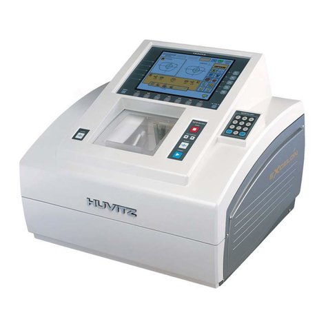
Huvitz SMART BLOCKER HBK-410 User manual

SMART BLOCKER
HBK-410
USER MANUAL

2
IMPORTANT NOTICE
This product may malfunction due to electromagnetic waves caused by portable personal
telephones, transceivers, radio-controlled toys, etc. Be sure to avoid having the above objects,
which affect the normal operation of the product, brought near the product.
The information in this publication has been carefully checked and is believed to be entirely
accurate at the time of publication. HUVITZ assumes no responsibility, however, for possible
errors or omissions, or for any consequences resulting from the use of the information contained
herein.
HUVITZ reserves the right to make changes in its products or product specifications at any time
and without prior notice, and is not required to update this documentation to reflect such
changes.
9000ENG0071-A
Ver 1.0 (Mar. 2019)
©2019 HUVITZ Co., Ltd.
38, Burim-ro 170beon-gil, Dongan-gu, Anyang-si, Gyeonggi-do, 14055, Republic of Korea
All rights reserved.
Under copyright laws, this manual may not be copied, in whole or in part, without the prior written
consent of HUVITZ Co., Ltd.

3
HBK-410
CONTENT
1. Introduction....................................................................................................................6
1.1. Main Features......................................................................................................................................6
1.2. System Configuration ..........................................................................................................................7
1.3. Classification........................................................................................................................................7
2. Safety Information..........................................................................................................8
2.1. Introduction ..........................................................................................................................................8
2.2. Safety Symbols....................................................................................................................................9
2.3. Environmental Considerations ..........................................................................................................10
2.4. Safety Precautions ............................................................................................................................12
3. System Overview .........................................................................................................15
3.1. Front View..........................................................................................................................................15
3.2. Rear View ..........................................................................................................................................15
3.3. Standard Accessory...........................................................................................................................16
4. Installation....................................................................................................................17
4.1. Installation Procedure........................................................................................................................17
4.2. How to connect the device ................................................................................................................17
5. Smart Blocker User Interface....................................................................................... 19
5.1. Main Screen.......................................................................................................................................19
5.1.1. Side Button.........................................................................................................................19
5.1.2. Job Management ...............................................................................................................22
5.1.3. Frame Information .............................................................................................................24
5.1.4. Layout Option.....................................................................................................................24
5.1.5. Edging Option ....................................................................................................................28
5.1.6. Lens Information ................................................................................................................33
5.1.7. Function Button..................................................................................................................37
5.2. Blocking Screen.................................................................................................................................38
5.2.1. Layout Information .............................................................................................................39
5.2.2. Lens Type...........................................................................................................................39
5.2.3. Tool Button .........................................................................................................................40
5.2.4. Sending Job .......................................................................................................................40
5.2.5. Exit .....................................................................................................................................40
5.3. Digital Scan........................................................................................................................................42
5.4. Job Manager......................................................................................................................................45
5.4.1. Job selection tab................................................................................................................46
5.4.2. Function Button..................................................................................................................46
5.4.3. Waiting Job ........................................................................................................................47
5.4.4. Working Job .......................................................................................................................47
5.4.5. Completed Job...................................................................................................................48
5.4.6. Job Search .........................................................................................................................49

4
5.5. Digital Pattern ....................................................................................................................................51
5.5.1. Enlargement/Reduction .....................................................................................................52
5.5.2. Near Vision Area Enlargement/Reduction ........................................................................53
5.5.3. Rotation..............................................................................................................................54
5.5.4. Partial Modification ............................................................................................................56
5.5.5. Toggle R/L Sync.................................................................................................................58
5.5.6. Reset ..................................................................................................................................59
5.5.7. Exit .....................................................................................................................................59
5.6. Hole Editor .........................................................................................................................................60
5.6.1. Upper Side of Hole Editor..................................................................................................61
5.6.2. Working Area......................................................................................................................61
5.6.3. Preview ..............................................................................................................................63
5.6.4. Function Buttons ................................................................................................................64
5.6.5. List of Hole/Slot..................................................................................................................71
5.6.6. Property of Hole/Slot .........................................................................................................74
5.7. Job Editor...........................................................................................................................................75
5.7.1. Layout Option.....................................................................................................................75
5.7.2. Edging option.....................................................................................................................76
5.8. Step Bevel Editor...............................................................................................................................77
5.8.1. Step Bevel Processing Mode ............................................................................................78
5.8.2. Partial Step Bevel Editing Area .........................................................................................78
5.8.3. Partial Step Bevel Option ..................................................................................................81
5.8.4. Full Step Bevel Editing Area..............................................................................................82
5.8.5. Full Step Bevel Option.......................................................................................................84
5.8.6. Fine Tuning ........................................................................................................................84
5.8.7. Preview ..............................................................................................................................88
5.8.8. Current Position Information..............................................................................................89
5.8.9. Safety beveling & Polishing option....................................................................................90
5.8.10. Reset & Apply Button.........................................................................................................91
5.9. Bevel Height Editor............................................................................................................................92
5.9.1. Editing Area........................................................................................................................93
5.9.2. Preview ..............................................................................................................................95
5.9.3. Current Position Information..............................................................................................96
5.9.4. Edging Option ....................................................................................................................97
5.9.5. Reset & Apply Button.........................................................................................................97
6. Configuration ...............................................................................................................98
6.1. Preference .........................................................................................................................................99
7. System Maintenance.................................................................................................. 106
7.1. Brightness Test & Calibration ..........................................................................................................106
7.2. Save Image......................................................................................................................................107
7.3. Test Mode ........................................................................................................................................108
7.4. Date & Time.....................................................................................................................................109
7.5. Touch Test........................................................................................................................................110
7.6. Configuration Management.............................................................................................................111
7.7. SW Upgrade ....................................................................................................................................112
7.8. Maintenance Code ..........................................................................................................................113

5
HBK-410
7.9. Maintenance Tips ............................................................................................................................114
7.9.1. Fuse Replacement...........................................................................................................114
7.9.2. Regular maintenance ......................................................................................................114
7.9.3. Cleaning ...........................................................................................................................114
8. Troubleshooting Guide ...............................................................................................115
9. Specifications and Accessories..................................................................................116
9.1. Standard Accessories......................................................................................................................116
9.2. Specifications...................................................................................................................................116
9.3. Drawings of System.........................................................................................................................117
10. SERVICE INFORMATION ...........................................................................................118

6
Introduction
This product is the device for blocking, which means mounting the adapter on the lens. The operator
adjusts the position of the lens using camera image and information for edging and performs the
blocking manually.
1.1. Main Features
•This product provides a different guide for blocking, depending on the type of lens such as a lens
marked by lens-meter, bifocal lens and progressive lens. And the guide can be adjusted. This
makes blocking more convenient.
•9.7”LCD display and touch screen are harmonized to offer the actual size (Frame, PD and FPD
etc.) display and the maximum convenience for everyday use.
•User can design all information about layout and edging at one page, and send it to other two
edger machines at a same time.
•This device provides the Digital Pattern function to transform the frame shape and the Hole Editor
function to support drilling.
•The Digital Scanning technology can scan a frame shape for a demo lens without a conventional
tracer. This provides you an enormous convenience and a time saving.
•Frame data is saved in SD memory card permanently. Therefore, you can load them whenever
you want.
1

7
HBK-410
1.2. System Configuration
•Interface the Smart Blocker with frame reader and edger.
Smart Blocker
Frame Reader
Edger
1.3. Classification
This device complies with Part 15 of the FCC Rules. Operation is subject to the following two
conditions: (1) this device may not cause harmful interference, and (2) this device must accept any
interference received, including interference that may cause undesired operation.
•Class A equipment
Class A equipment is intended for use in an industrial environment. In the documentation for the
user, a statement shall be included drawing attention to the fact that there may be potential
difficulties in ensuring electromagnetic compatibility in other environments, due to conducted as
well as radiated disturbances.
•Protection against electric shock: Class I (when earthed)
•Measurement Category: CAT II
•Pollution Degree: 2

8
Safety Information
2.1. Introduction
Safety is everyone’s responsibility. The safe use of this machine is largely dependent upon the
installers, users, operators, and managers. It is prerequisite to read and understand these specifications
before installing, using, cleaning, fixing or revising. Fully understanding the whole instructions must be
the first priority. For this reason, the following safety notices have been placed appropriately within the
text of this manual to highlight safety related information or information requiring special emphasis. All
users, operators, and maintainers must be familiar with and pay particular attention to all signs of
Warnings and Cautions.
“Warning” indicates the presence of a hazard that could result in severe personal injury, death or
substantial property damage if ignored.
“Caution” indicates the presence of a hazard that could result in minor injury, or property damaged
if ignored.
This is used to emphasize essential information.
Be sure to read this information to avoid operating the device incorrectly.
2
!
WARNING
!
CAUTION
!
NOTE

9
HBK-410
2.2. Safety Symbols
The International Electrotechnical Commission (IEC) has established a set of symbols, which are listed
below. This applies only to the instrument that has the certification symbol printed explicitly on the
product label or sticker.
I and O on power switch represent ON and OFF respectively.
(I et O sur l'interrupteur d'alimentation représentent ON et OFF
respectivement.)
This symbol identifies caution, risk of danger. Ensure you understand
the function of this control before using it. Control function is
described in the appropriate User’s or Service Manual.
(Ce symbole identifie la prudence, le risque de danger. Assurez-vous
de bien comprendre le fonctionnement de ce contrôle avant de
l’utiliser. La fonction de contrôle est décrite dans le manuel de
l’utilisateur ou de service approprié.)
Protective Earth Connection
(Connexion de protection à la terre)
Disposal of your old appliance
1. When this crossed-out wheeled bin symbol is attached to a
product it means the product is covered by the European
Directive 2002/96/EC.
(Lorsque ce symbole de poubelle à roulettes barrée est attaché à
un produit, cela signifie que le produit est couvert par la directive
européenne 2002/96 / CE.)
2. All electrical and electronic products should be disposed of
separately from the municipal waste stream via designated
collection facilities appointed by the government or the local
authorities.
(Tous les produits électriques et électroniques doivent être
éliminés séparément du flux de déchets municipaux via des
centres de collecte désignés par le gouvernement ou les autorités
locales.)
3. The correct disposal of your old appliance will help prevent
potential negative consequences for the environment and human
health.
(La mise au rebut correcte de votre ancien appareil aidera à
éviter les conséquences négatives potentielles sur
l'environnement et la santé humaine.)
4. For more detailed information about disposal of your old
appliance, please contact your city office, waste disposal service
or the shop where you purchased the product.
(Pour plus d'informations sur l'élimination de votre ancien

10
appareil, veuillez contacter votre mairie, le service d'élimination
des déchets ou le magasin où vous avez acheté le produit.)
Alternating Current
(Courant alternative)
2.3. Environmental Considerations
Avoid the following environments for operation or storage:
Where the machine is exposed to water vapor.
Don’t operate the machine with wet hands Indoor use only.
Where the machine is exposed to direct sunlight.
A place where the equipment can be exposed to direct ultraviolet.
Where there are big changes in temperature.
Where there is a hot equipment nearby.
Where the humidity is extremely high or there is a ventilation
problem.
Where the machine is exposed to excessive shocks or vibrations.
Where the machine is exposed to chemical material or explosive
gas.

11
HBK-410
Be cautious so that things like dust and metal do not fall inside the
machine.
Don’t disassemble or open the product. HUVITZ does not take
responsibility for the possible problems
Be careful not to block the fan of the machine.
Don’t plug the AC power cord into the outlet unless all parts of the
machine are completely connected. Otherwise, it will cause severe
damage on the machine.
Pull out the power cord with holding the plug, not the cord.
To avoid risk of electric shock, this equipment must only be
connected to a supply mains with protective earth.
This instrument must be followed by these following conditions:
•Operation
An ambient temperature range of 10℃~ 40℃
A relative humidity range of 30% ~ 90%
An atmospheric pressure range of 800 ~ 1060hpa
An indoor use, Altitude up to 2000 m
•Transportation
An ambient temperature range of -40℃~ 70℃
A relative humidity range of 10% ~ 95% (with non-condensing)
An atmospheric pressure range of 500 ~ 1060hpa
•Storage
An ambient temperature range of -10℃~ 55℃
A relative humidity range of 10% ~ 95% (with non-condensing)
An atmospheric pressure range of 700 ~ 1060hpa
•Temporary Overvoltage
Short-term temporary overvoltage: 1440V
Long-term temporary overvoltage: 490V
Please avoid where the equipment is exposed to excessive shocks or vibration.

12
2.4. Safety Precautions
This machine has been developed and tested according to safety standards as well as national and
international standards. This guarantees a very high degree of safety for this device. HUVITZ is legally
required to inform the users of all the information regarding safety. Observance of the instructions is the
requirement for the safety. Therefore, please read carefully all instructions before switching on this
machine. For more detailed information, please contact our Customer Service Department or one of our
local agencies.
1. This equipment must not be used (a) in an area that is in danger of explosions and (b) in the
presence of flammable, explosive, or volatile solvent such as alcohol, benzene or similar
chemicals.
2. Do not place or store this machine in humid area. Do not expose the device to water splashes,
dripping water, or sprayed water. Do not place containers with fluids, liquids, or gases on top of
this machine.
3. The machine must be operated by a trained and qualified person or under his or her supervision.
4. Repair of this machine must be conducted by HUVITZ’s service technicians or other authorized
persons.
5. Maintenance by users must observe the User’s Manual and Service Manual. Any additional
maintenance may only be performed by HUVITZ’s service technicians or other authorized persons.
6. Manufacturers are responsible for the safety, reliability, and performance of this machine only
when the following requirements are fulfilled: (1) When the machine has been installed in a proper
area, following the manual. (2) When the machine has been operated and maintained according to
the manual and service manual.
7. Manufacturers are not responsible for the damages caused by unauthorized alterations. Such
tampering will forfeit any rights to receive services during the term of guarantee.
8. This machine must be connected with the accessories supplied by HUVITZ. If you are to use other
accessories, their safety or usability must be checked and proved by their manufacturers or
HUVITZ.
9. Only those who have undergone proper training and instructions are authorized to install, use,
operate, and maintain this machine.
10. Keep the User’s Manual and Service Manual in a place easily accessible at all times for persons
operating and maintaining the equipment.
11. Do not apply excessive force to cable connections. If the cable does not connect easily, make sure

13
HBK-410
that the connector (plug) is appropriate for the receptacle (socket). If you caused any damage to a
cable connector(s) or receptacle(s), let the damage(s) be repaired by an authorized service
technician.
12. Please do not pull on any cable. Always grab the plug when disconnecting cables.
13. Before you use, check the exterior of the machine and its conditions.
14. Do not block any ventilation outlet necessary for proper heat dissipation.
15. If smoke, sparks or any abnormal noise or smell is noticed coming from the machine, please
switch the power off immediately and pull out the plug.
16. Dispose of used batteries according to the regulations. If not, there is the possibility of an
explosion.
17. To avoid the risk of electric shock, this machine must only be connected to protective earth.
18. Do not place the machine where it is difficult to operate the disconnecting device. (disconnecting
device: power cord)
19. The machine may be impaired if it is used in a manner not specified by the manufacturers or
manual.
•Do not put your hands into the machine while blocking. Otherwise, it may cause serious injury.
•Do not block without lens adaptor, otherwise the lens may be broken or scratched.
•Do not disassemble the product without proper training. It may cause electric shock, serious
injury during the operation or cause malfunction of the product.
•The product should be properly installed and maintained at where the ground is even and flat.
Otherwise, it may affect the normal operation of the product.
!
WARNING

14
•When moving the machine, first fix the stage and check whether the power supply is off.
Then, should lift the bottom of the product with both hands.
•When setting down the machine, make sure not to be interfered with the obstacles. Set down
the product slowly in order to prevent any injury of human body or damage to the product.
•When moving the machine, make sure the locking device and the screw for the cover are
properly tightened.
•When wrapping the machine, use recommended packaging and shock-absorbing materials in
order to prevent damage during the transportation.
•Be sure to use the standard accessories or tools provided together with the product for the
maintenance. Otherwise, it may cause the malfunction of the product.
•Changes or modifications not expressly approved by the party responsible for compliance
could void the user's authority to operate the equipment.
This equipment has been tested and found to comply with the limits for a Class A digital device,
pursuant to Part 15 of the FCC Rules.
These limits are designed to provide reasonable protection against harmful interference when the
equipment is operated in a commercial environment.
This equipment generates, uses, and can radiate radio frequency energy and, if not installed and
used in accordance with the instruction manual, may cause harmful interference to radio
communications. Operation of this equipment in a residential area is likely to cause harmful
interference in which case the user will be required to correct the interference at his own expense.
!
CAUTION
!
NOTE

15
HBK-410
System Overview
3.1. Front View
Display
(Touch Screen)
Lens Supporter
Blocking Arm
Reflector
3.2. Rear View
SD card slot
Power Switch
Interface Terminal
•EDGER 1
•EDGER 2
•Barcode Reader
•Tracer
Main Power Input and Fuse
3

16
3.3. Standard Accessory
Lens Supporter
Lens Supporter for Frame Change and Digital Scanning
Touch Pen
•Please use genuine lens adaptor tape (LEAP-III). Otherwise, the lens axis may move.
•We do not provide a sticker for Super Hydrophobic Lens, but you should use qualified ones, or
the lens axis may move.
!
NOTE

17
HBK-410
Installation
4.1. Installation Procedure
①Remove the shock-absorbing materials from the packing box and take out the smart blocker
carefully.
②Remove the shock-absorbing materials from the blocking arm.
③Plug the Power Cable into the socket at the rear side of the product and turn on the power.
④If the initial indicator disappears and the main screen is shown on the LCD, check if the touch
screen is responding correctly by touching icons or else.
4.2. How to connect the device
In this manual, HFR-8000X frame reader and HPE-8000X edger are used as an example.
HFR-8000X Rear view
HBK-410 Rear view
HPE-8000X Rear view
4
1
2

18
①Connect a 9-pin serial cable to the EDGER 1 port of the HFR-8000X and the TRACER port of the
HBK-410.
②Connect a 9-pin serial cable to the EDGER 1 port of the HBK-410 and the TRACER/BLOCKER
port of the HPE-8000X.
③After connecting the cables, turn on the power of all the devices and check the initialization
process is performed properly.
④Read the frame from the frame reader and transfer the data to the blocker. And then check the
blocker is receiving the job data normally.
⑤From the blocker, open the job data and switch to the blocking screen and then send the job data
to the edger. (For the UI screen description, refer to ‘Chapter 5.2 Blocking Screen’)
⑥Make sure that the edger receive the job data from the blocker normally.
Keep the shock-absorbing material in the box and use them again when you move the machine.
!
NOTE

19
HBK-410
Smart Blocker User Interface
5.1. Main Screen
5.1.1. Side Button
①Press the R button to select right side.
②Press the L button to select left side.
5
1
2
Function Button
Edging Option
Lens
Information
Function Button
Side Button
Frame Information
Job Management
Layout Option

20
•Each side of frame shape is exchanged by pressing the R button for a while.
•Left and Right sides are exchanged. The other job options remain unchanged.
•The function of exchange R/L is useful when you selected wrong side while reading demo lens
or patterns.
•In addition to R/L exchange, R/L shape mirroring function is available by setting the preference
option. (Refer to ‘Chapter 6.1 Preference’)
!
NOTE
Table of contents
Other Huvitz Laboratory Equipment manuals

Huvitz
Huvitz HNT-1 Operating instructions

Huvitz
Huvitz HNT-7000 User manual

Huvitz
Huvitz CME-9000 User manual

Huvitz
Huvitz Excelon CAB-4000 User manual

Huvitz
Huvitz Excelon User manual

Huvitz
Huvitz Excelon XD User manual

Huvitz
Huvitz HRK-7000 User manual

Huvitz
Huvitz Excelon CAB-4000 User manual

Huvitz
Huvitz HLM-9000 User manual

Huvitz
Huvitz CRK-7000 User manual
Popular Laboratory Equipment manuals by other brands

Biosan
Biosan S-Bt Service manual

Kent Scientific
Kent Scientific MouseSTAT Jr Owners manual and set-up guide

cytiva
cytiva OligoPilot 400 operating instructions

Metrohm
Metrohm 785 DMP Titrino Instructions for use

Christ
Christ Epsilon 1-4 LSCplus operating manual

Bibby Sterilin
Bibby Sterilin Stuart SF1 Instructions for use