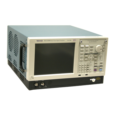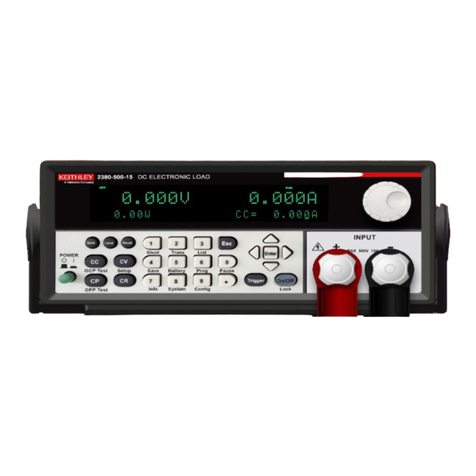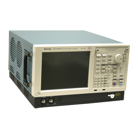
The Tektronix 475 Oscilloscope is a dual-channel
portable instrument. The dual-channel dc-to-200 MHz
vertical system provides ca librated deflection factors lrom
2 millivolts to 5 volts,/division. The sweep trigger circuits
are capable of stable triggering over the lull bandwidth
capabilities of the vertical detlection system. The horizon-
tal dellection system provides calibrated sweep rates trom
0.5 second to 0.0'l microsecond/division along wilh
delayed sweep features lor accurate relative-time
measurements. A X1O magnifier extends the calibrated
sweep rate to 1 nanosecond/division. The instrument
operales over a wide variation of line voltages and
frequencies. Maximum power consumption is about
100 watts.
The Tektronix DM44 Digital Multimeter measures O
ohm to 20 megohms, 0 dc vott to 1200 dc volts (+ or -), or
(using the temperature probe) -55oC to +150"C. The
measurement is displayed on a 3-1/2 digital display while
the oscilloscope operates normally.
BEFORE OPERATING
The digital multimeter and oscilloscope combine to
provide a digital readout ot the time between any two
points on the oscilloscope display. Both time measure-
ment points are displayed on the crt at the same time. The
1/TIME function can provide direct measurement ol
frequency.
SAFETY INFORMATION
The instrument is designed to operate lrom a single-
phase power SOUrce with one of the current-carrying
conductors (the Neutral Conductor) at ground (earth)
potential. Operation lrom power sources where both
current-carrying conductors are live with respect to
ground (Such as phase-to-phase on a three-wire system)
is not recommended, since only the Line Conductor has
over-current (tuse) protection within the instrument.
The instrument has a three-wire power cord with a
three-terminal polarized plug for connection to the power
source and safety-earth. The ground (earth) terminal of
the plug is directly con nected to the instrument rrame. For
electric-shock protection, insert this plug only in a mating
outlet with a salety-earth contact.
1
@475/DM44 Operators
INTRODUCTION
Scan by vintageTEK - Your donations help support the museum - vintagetek.org
