TEL AFA4000/1/AS Use and care manual

AFA4000/1/AS
Airow Monitor with
Auto Sash Controller
Installation and calibration guide

AFA4000/1/AS Airow Monitor / p.2
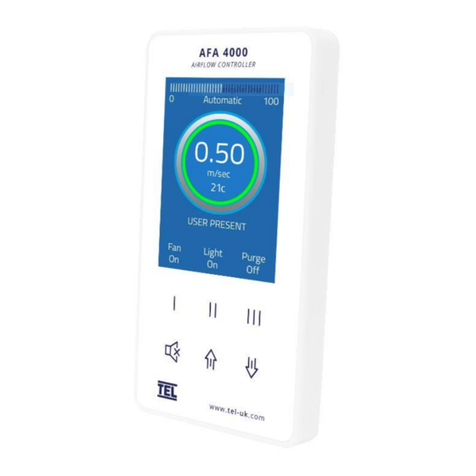
A – Airow bar-graph or timeline display
B – Airow velocity display with LED halo (red/amber/green)
C – Status window, airow alarm and auto sash status
D – Auto Sash Up/Down/Cancel Buttons, Menu Pushbuttons
& Alarm Mute
The AFA4000/1/AS Airow monitor is integrated with the Auto Sash Controller, to Set up the
Airow monitor, the Auto Sash controller should be Disabled, Disconnected or Not Congured,
this ensures that the sash is under manual control whilst the Airow monitor is commissioned.
The Airow monitor auto detects that the Auto Sash controller is connected, the Auto Sash
menus and Operation status will not be displayed if the Auto sash is not connected.
The AFA4000/1/AS must be eld-calibrated once the room air supply and exhaust is
proportionally balanced. When the unit is powered up, the following sequence of events occurs:
1. The alarm performs a self-test of its functions and audible alarm (approximately 3 seconds)
2. At the end of the delay, the unit will do one of two things:
a.IftheAirowmonitorhasbeencalibrated,theunitentersnormaloperatingmode(displaysairow
velocity, LED’s and audible alarm enabled).
b.IftheAirowmonitorhasnotbeencalibrated,theunitwilldisplay“Requiressetup,pressMuteto
continue”
c. If the Auto Sash Controller has been calibrated, the unit enters normal operating mode (displays
status and alarms in the status window).
d.IftheAutoSashControllerisconnectedandhasnotbeencalibrated“AutoSashNotCongured”will
be displayed in the status window.
e. If the Auto Sash Controller is disconnected, the Auto sash controller status and menus will not be
shown.
Operator Panel
Overview
Startup
A
B
C
D

AFA4000/1/AS Airow Monitor / p.3
1. PressMutefromthe“Requiressetup”screenorifthemonitorisintheRunScreenPress
andHoldtheMutebuttonfor5secondsuntiltheMainMenuisdisplayed.
2. Using the ↑/ ↓buttonsselectSETUPMONITOR,thenselectCALIBRATION,thenenterthe
password(thefactorydefaultpasswordis0-0-0-0),pressMutetocontinue.
3. With the sash open to the normal operating height measure the face velocity using a
calibrated instrument. Using the ↑/ ↓buttons enter the measured face velocity then press
Mute,themonitorwillthensampletheairowfor5seconds.
4. Iftheairowsampleisunstablethemonitorwilldisplay“DeviationstooHigh”,followthe
instructionstorepeatthesampleorquitthecalibration.
5. If the sample is accepted, lower the sash by half and measure the face velocity using a
calibrated instrument. Using the ↑/ ↓buttons enter the measured face velocity and press
Mute,themonitorwillthensampletheairowfor5seconds.
6. IfthecalibrationissuccessfulthemonitorwillreturntheMainMenu,selectRUNtogoto
normal operating mode and check the velocity reading is accurate and stable.
7. Iftheairowsampleisunstablethemonitorwilldisplay“DeviationstooHigh”,followthe
instructionstorepeatthesampleorquitthecalibration.
8. Themonitorwilldisplay“Increasehigherairowsample”ifthesecondsamplevalueistoo
closetotherstvalueentered,closethesashalittleandrepeatthehighersample.The
minimumdierencebetweenthesamplesthatthemonitorwillacceptis0.3m/sec(60fpm).
9. Themonitorwilldisplay“Sensorditoolow”ifthemonitordoesn’tdetectanydierencein
thesensoroutputbetweenthe2airowsamples,checkthatthesensorhoseisconnected
and repeat the calibration.
10. IfthecalibrationisstableandaccuratePressandHoldtheMutebuttonfor5secondsuntil
theMainMenuisdisplayed.
11. ThemonitorwillreturntotheMAINMENU,selectRUNtogotonormaloperatingmode.
Airow Monitor Calibration

AFA4000/1/AS Airow Monitor / p.4
1. Ensure that the sensor hose is connected correctly at the side wall and rear of the sensor.
2. Ensure that the extract fan is running and the Fume Cupboard is balanced before
calibrating the monitor.
3. Takeextratime(atleast15to20seconds)towaitfortheairowtosettlebeforecapturing
theairowsamples.Thiswillminimizethechanceofacalibrationerrorduetoturbulence
oructuations.
4. Avoid movement in front of the Fume Cupboard whilst calibrating the monitor.
5. TheLowandHighairsamplesmustbeatleast0.3m/sec(60fpm)aparttocalibratethe
monitor.Thisistoavoidinaccuracyinthecalibrationsuetoinsucientdierencebetween
thesamples.Theminimumdierencecanbechangedinthe“LowHighdi”parameterin
theCalCongmenu.
6. Do not use fully open and fully closed sash positions for the calibration points, the
recommendedpositionsarenormaloperatingheight(e.g.500mm20”)fortherstsample
andapproximatelyhalfthesashopening(e.g.250mm10”)forthesecondsample.
The MONITOR CONFIG menu includes the following coms parameters: -
1. PROTOCOL –SetsModbusRTU,BACnetMS/TPorTELprotocol.
2. MODBUS SETTINGS –SetsSlaveID,BaudRateandParityfortheModbusprotocol.
3. BACnet SETTINGS – SetstheDeviceInstance,StationID,BaudRate,ParityandMaxMasters
fortheBACnetprotocol.
TheTELprotocolisusedtoconnectedtoTELCongManagersoftwareandtheTELAFA5000
RoomSpaceController,theModbusSlaveIDisusedwhensettoTELprotocol.
Airow Monitor Calibration Tips
Airow Monitor Coms Settings

AFA4000/1/AS Airow Monitor / p.5
Troubleshooting
Problem Check for: -
No LED’s, Screen blank Check the power supply is securely plugged into the monitor.
Check the power supply is securely plugged into the mains power socket.
Checkthatthereis15VDCpowersupplyonthemonitorterminals(brokenwireor
snagged cable sheath)
Sensor Error message Check the sensor cable is securely plugged into the sensor.
Check the sensor cable is securely plugged into the monitor.
Replacethesensor.
If Sensor Error message still displayed replace the sensor cable.
If Sensor Error message still displayed replace the monitor.
Audible alarm not working Checkforscreenmessages-ifSETBACKisdisplayedthemonitorhasbeenremotely
muted.
CheckifalarmhasbeendisabledinCalCongmenu.
RS485 Coms not connected See Diagnostics menu, Coms Data.
CheckthecorrectProtocol,SlaveID,BaudRate,Parityhavebeenset.
Tx&Rx=0-AFA4000isnotconnectedtothenetwork
Tx&Rx>0butxedvalues–AFA4000haslostconnectiontothenetwork
RxiscountingbutTxisaxedvalue–AFA4000Isconnectedtothenetworkbutthe
MasterisoineornotpollingtheAFA4000.

AFA4000/1/AS Airow Monitor / p.6
Press the ↑/ ↓ buttons together from the Run screen to access the Diagnostics menu,
the menu contains the following Input and Output data: -
Diagnostics Menu
Menu Parameter Action
Alarm Test Sounds the Audible Alarm
Coms Data Displays the following: -
Protocol,SlaveID,BaudRate,Parity
Tx–NumberofDataPacketstransmitted(incrementswhentransmitting)
Rx–NumberofDataPacketsreceived(incrementswhenreceiving)
I/O Status Input Data Displays the following: -
Input1–On/OorAnalogueVoltagestatus
Input2–On/OorAnalogueVoltagestatus
Input3–On/OorAnalogueVoltagestatus
OutputData Displays the following: -
Relay1–On/Ostatus
Relay2–On/Ostatus
Relay3–On/Ostatus
Sensor Data Displays the following: -
Airowsensorstatus0-100%(100%=0airow,0%=maxow)
Temperature°Cor°F(OptionalwithadditionalTemperaturesensortted)

AFA4000/1/AS Airow Monitor / p.7
The Tiptronic Auto Sash Controller contains the following features: -
1. Auto Close
2. AutoOpen(userselectable-enabled/disabled/autoopenifautoclosedonly)
3. TiptronicOpen/Close-touchsensitivesashmovement(menuselectable)
4. Sash Lock (Drive disable with alarm)
5. Manualsashoperation
6. AFA4000PushbuttonOpen/Close
7. FootswitchOpen/Close(optional)
8. BMSinputs:Open/Close+EmergencyOpen/Close+FireAlarmClose
9. BMSoutputs:SashOpen/Closedvoltfreecontact+Sashposition(0-10v/4-20mA)+External
Alarm Sounder output
Auto Sash Controller Features

AFA4000/1/AS Airow Monitor / p.8
The Tiptronic Auto Sash Controller operation is as follows: -
1. User Present
When the user is detected the sash can be moved in the following ways: -
a.Manually-ifthetiptronicfeatureisenabledthesashcanbemanuallymovedifitiskept
moving for more than 1 second.
b. Tiptronic - if the sash is manually moved for less than 1 second the sash will auto drive
to its calibrated position.
c. ↑/ ↓pushbuttons - if pressed the sash will auto drive to its calibrated position.
d. Footswitch (open and close options) - if operated the sash will auto drive to its calibrated
position.
2. User not detected: -
When the user is not detected the sash will auto close to its calibrated position following a pre-
set delay time unless: -
a. The sash beam is broken (object detected in the sash opening).
b. The controller detects no movement in the sash when the motor is driving.
3.AutoOpen(usercongurable):-
When enabled the sash will drive open when the operator returns following a pre-set time delay:
-
a. If the sash was Auto closed the sash will Auto open back to the same position the sash
was in before the Auto close.
b.Ifthesashwasclosedbyanyothermethod(manually,tiptronically,pushbutton,BMS
etc) the sash will Auto open back to its calibrated position.
The sash will not Auto open if: -
a. The sash beam is broken (object detected in the sash opening).
b. The controller detects no movement in the sash when the motor is driving.
Operation

AFA4000/1/AS Airow Monitor / p.9
4.BMSinputs:-
ThesashcanbesettooperatefromtheBMSinputsasfollows:-
a.Open/Close-forsinglestartorendofdayoperationfromBMSinput
The sash will only drive if the user is not present and the sash beam is clear.
b.EV(Emergency)Open/Close(EVaudiblealarmtonewillsoundwhilsttheEVinputisactive).
Thesashwillonlydriveiftheuserisnotpresentandthesashbeamisclear.InEVmodethesash
can be manually moved if the user is detected. The sash will then auto drive closed/open again if
theEVinputisstillactivewhentheuserisnotdetected.
c. Fire Alarm Close (Fire Alarm audible alarm tone will sound whilst the Fire Alarm input is active)
The sash will only drive if the user is not present and the sash beam is clear. In Fire Alarm mode
the sash can be manually moved if the user is detected. The sash will then auto drive closed/open
againiftheEVinputisstillactivewhentheuserisnotdetected.
5. Sash Lock: -
The sash can be set to Lock (Auto Sash Drive Inhibited) when the sash is set to a calibrated position
(e.g. fully open). An audible and visual alarm will activate following a preset alarm delay period to
remind the user to lower the sash.
This function is used when the sash needs to remain in the open position for a prolonged period of
timetoallowloadingorsettingupofequipmentinsidetheFumeCupboard.

AFA4000/1/AS Airow Monitor / p.10
Ensure that the Auto Sash Controller is fully installed before attempting to calibrate
the controller. On power up: -
1. The alarm performs a self-test of its functions, LEDs and audible alarm (approximately 3
seconds).
2. During the self-test period, all inputs and outputs are deactivated.
3. At the end of the delay, the unit will do one of two things:
a. If the controller has previously been calibrated, the controller enters normal operating
mode (displays current status or alarm condition).
b. If the unit has not been calibrated, when the Tilt switch input is open the display will
show“SashDriveInhibited”,whentheTiltswitchinputisclosedthestatuswindowwill
show“AutoSashNotCongured”.
1. PressandHoldtheMUTEbuttonforapprox5secondsorUntiltheMAINMENUappears.
2. Using the ↑/ ↓buttonsselectSETUPAUTOSASH,thedisplaywillshow“TELSASHCLOSER”
3. PresstheMutebuttonshowthecurrentHardwareandSoftwareversionse.g.“1.HW2.0
FW1.1”
4. Press the ↓buttontoscrolldownandselect“SETUPMENU”andpressMute.
5. EnterthePASSWORD(Factorydefaultis1-0-0-1)usingthe↑andMutebuttons.
6. IntheSetupmenuthecontrollerwilldisplay“SYSTEMPROFILE”
7. Use the ↓buttontoscrollthroughthemenuandselect“Sash1Settings”andpressMute.
8. IntheS1Settingsmenuthedisplaywillshow“1.S1Enabled”
Startup
Calibration — Tiptronic
1, 2 or 3 position calibration

AFA4000/1/AS Airow Monitor / p.11
9. Use the ↓buttontoscrollthroughthemenuandselect“8.S1Calibration”andpressMute.
10. The display will show on screen instructions.
11. Setthesashtothecentree.g.250mmopening.
12. Press the ↑/ ↓buttonstondwhicharrowrepresentsthesashclosing(e.g.downarrow)and
PressMute.Note-thistellsthecontrollerwhichdirectionthemotorneedstodrivetoclose
the sash.
13. FullyClosetheSashandPressMute.Note–thissetsthesashpositionsensoroutput0V
position.
14. FullyOpentheSashandPressMute.Note–thissetsthesashpositionsensoroutput10V
position.
15. SetthesashtothebottompositionandPressMute.
16. Press Quit (↑/ ↓together)ifonlybottompositionrequired(closeonly)OR:
17. Setthesashtothenormalworkingheight(e.g.500mm)andpressMutefor2position
operation.
18. Press Quit (↑/ ↓together)ifonly2position(bottomandmiddle)requiredOR:
19. Setthesashtothefullopeningheight(e.g.750mm)andpressMutefor3positionoperation.
20. Bottom,middleandtoppositionsarenowcalibrated,pressMutetoquitcalibrationmode.
18. Use the ↓buttonandselect”BacktoSetupmenu”andpressMute.
19. Use the ↓ buttonandselect”ExitandSaveChanges”andpressMute.
20. The controller will now go to run mode.
Even though the sash drive has acceleration and deceleration the sash may slightly over run past
the calibration points if the sash motor drive is set to a very fast speed. When calibrating the
sash positions allow a margin for the sash to over travel past the calibration height e.g. bottom
positioncalibration,closesashfullyandopen5mmbeforecalibrating,normalheightcalibration,
opensashtothenormalheightandlowerby5mmbeforecalibrating.
Calibration Notes

AFA4000/1/AS Airow Monitor / p.12
1. PressandHoldtheMUTEbuttonforapprox5secondsorUntiltheMAINMENUappears.
2. Using the ↑ / ↓buttonsselectSETUPAUTOSASH,thedisplaywillshow“TELSASHCLOSER”
3. PresstheMutebuttonshowthecurrentHardwareandSoftwareversionse.g.“1.HW2.0FW1.1”
4. Press the ↓buttontoscrolldownandselect“SETUPMENU”andpressMute.
5. EnterthePASSWORD(Factorydefaultis1-0-0-1)usingthe↑andMutebuttons.
6. IntheSetupmenuthecontrollerwilldisplay“SYSTEMPROFILE”
7. Use the ↓buttontoscrollthroughthemenuandselect“Sash1Settings”andpressMute.
8. IntheS1Settingsmenuthedisplaywillshow“1.S1Enabled”
9. Use the ↓buttontoscrollthroughthemenuandselect“11.S1AutoLock”andpressMute.
10. SettoEnabledandpressMute.
11. Use the ↓buttontoscrollthroughthemenuandselect“11b.S1LockAlarm”andpressMute.
12. Use the ↑/ ↓buttonstosettherequiredalarmdelaytimeandpressMute.
13. Use the ↓buttontoscrollthroughthemenuandselect“11c.S1LockPosCalibration”andpressMute.
14. The display will show on screen instructions.
15. OpenthesashtotheLockpositionandpressMute.
16. Ifthepositionchosenistoolow(lowerthanthecalibratedBottom,MiddleorToppositions)“Bad
position - try again” will be displayed.
17. IfthechosenpositionisOKthelockpositionwillbeset.
18. Use the ↓ buttonandselect”BacktoSetupmenu”andpressMute.
19. Use the ↓buttonandselect”ExitandSaveChanges”andpressMute.
20. The controller will now go to run mode.
Calibration - Sash Lock Function

AFA4000/1/AS Airow Monitor / p.13
In run mode the AFA4000 Status Window will show the current status: -
1. “User present” - the user is detected, the sash drive is inhibited, Tiptronic & manual drive is enabled.
2. “XX Seconds to close” - the user is not detected; the sash will close following the countdown delay time.
3. “Sash Closing” will be displayed when the sash is driving closed (auto close, tiptronic, footswitch or
pushbutton).
4. “Sash Closed” - Theuserisnotpresentandthesashhasclosed.(KeypadBacklightdimmed).
5. “XX Seconds to open” the user is detected; the sash will open following the countdown delay time.(Auto
open enabled)
6. “Sash Opening” will be displayed when the sash is driving open (auto open, tiptronic, footswitch or
pushbutton).
7. “Operator Manual Move” will be displayed if the sash is manually opened or closed.
8. “Sash Inhibited” will be displayed if the Tilt switch input is open, drive is inhibited until Tilt switch is
closed.
9. “Sash Disabled” will be displayed if the sash drive has been disabled in the menu settings.
10. “Sash Locked” will be displayed if the sash is at or above the calibrated lock position.
Auto Sash Operation
and Alarm Indication
IftheAutoopenfeatureisenabledinthemenuandisswitchedonfromthekeypad:“*”(asterix)willbe
displayed in the left-hand corner of the Status Window, e.g. “* User present”.
ToenableAutoopenpressandholdtheMuteand↑buttonsfor1secondoruntilthe“*”symbolisdisplayed.
TodisableAutoopenpressandholdtheMuteand↑buttonsfor1secondoruntilthe“*”symboldisappears.
TheAutosashcanbesettobedisabled,enabledorUSRenabled,USRenableisUserenable/disable.
ToUserenabletheAutoSashPresstheMuteand↓buttons for 1 second.
ToUserdisabletheAutoSashPresstheMuteand↓buttonsfor1second.“USRdisabled”willbedisplayedin
the Status window.

AFA4000/1/AS Airow Monitor / p.14
Note-Autoopencanbesettodisabled/enabled/enabledifautoclosed.Ifsettoenabledifautoclosedthe
sash will only Auto open if the sash has Auto closed, closing the sash manually or by using the pushbuttons
will inhibit the Auto open when the user returns to the Fume Cupboard.
In an Alarm condition the Status Window will show the current alarm:-
1. “Obstruction Detected” will be displayed if the sash beam is broken when the sash starts to close -
removeobstructionandpresstheMutebuttontoresetthealarm.
2. “Sash Fault” willbedisplayedifthesashdoesnotcloseoropenwhenexpected-pressMutetoreset
alarm. Check sash drive for faults.
3. “Remove Sash Lock / Cancel to Reset” will be displayed if the sash is at or above the calibrated lock
positionforlongerthanthepresetalarmtime-pressMuteorlowerthesashtoresetthealarm.
When a BMS input is in an active condition the display will show the current alarm:-
1. “Fire Alarm” willbedisplayedalongwiththenormaltext(e.g.“FireAlarm,Userpresent”)whenthere
alarm input is activated - the sash will drive closed if the user is not detected and the sash is clear. The
sash can be operated manually if the user is detected (auto open, tiptronic & pushbuttons are disabled).
2. “BMS open” willbedisplayedalongwiththenormaltextiftheuserisnotdetectedwhentheBMSOpen
input is activated - the sash will drive open if the user is not present and the sash is clear. The sash can be
operated normally if the user is detected (auto open, tiptronic & pushbuttons are active).
3. BMS close input -whentheBMSCloseinputisactivatedthesashwilldriveclosediftheuserisnot
present and the sash is clear. The sash can be operated normally if the user is detected (auto open,
tiptronic & pushbuttons are active).
4. “Emergency (up)”willbedisplayedalongwiththenormaltextiftheuserisnotdetectedwhentheEV
Openinputisactivated-thesashwilldriveopeniftheuserisnotpresentandthesashisclear.Thesash
can be operated manually if the user is detected (auto open, tiptronic & pushbuttons are disabled).
5. “Emergency (dn)”willbedisplayedalongwiththenormaltextiftheuserisnotdetectedwhentheEV
Close input is activated - the sash will drive closed if the user is not present and the sash is clear. The sash
can be operated manually if the user is detected (auto open, tiptronic & pushbuttons are disabled).
6. “Sash Opening”willbedisplayediftheSashOpenFootswitchhasbeenoperatedwhilsttheoperatoris
present.
7. “Sash Closing” will be displayed if the Sash Close Footswitch has been operated whilst the operator is
present.

AFA4000/1/AS Airow Monitor / p.15
1. S1Enabled-Settopermanentlymenudisable/enablethedriveorKeypad(USR)disable/enablethe
drive(Enabled/Disabled/USREnabled).
2.S1AutoClose–SettoenableordisableAutoClose.
a.S1Closedelay-Setsthetimedelaybeforethesashcloses(0-3600seconds).
b. S1 Close Alarm - Sets alarm time delay - Time before Alarm activates before the sash closes (0-10
seconds).
3. S1AutoOpen-SettoenableordisableAutoOpenfeature(Enabled/Disabled/AutoCloseOnly).
a.S1OpenDelay-Setsthetimedelaybeforethesashopens(0-10seconds).
b.S1OpenAlarm-Setsalarmtimedelay-TimebeforeAlarmactivatesbeforethesashopens(0-10
seconds).
4. S1MotorVoltage–SetstheMotorVoltage(viaPasswordprotectedEngineeringmenu)
a.S1MotorSpeedOpen-Setsmotordrivespeed–sashopening(0-100%)
b.S1MotorSpeedClose-Setsmotordrivespeed–sashclosing(0-100%)
c.S1ClutchODelay–Setsarunontimefortheclutchtoremainenergizedoncethemotorstops
driving to aid braking.
5. S1TiltSwitch-Setsinputactivation(NormallyOpen/NormallyClosed/Disabled).
6. S1LightCurtain-Setsinputactivation(NormallyOpen/NormallyClosed/Disabled).
a.S1LightCurtainTest–ActivatessensortestifFailSafesensorswithTestwirearetted.
b.S1AutoClearObstruction–AutoresetsObstructionAlarmifObstructionisremoved.
7.S1PersonnelSensor-Setsinputactivation(NormallyOpen/NormallyClosed/Disabled).
a.S1PersonnelSensorPowerCycle–menusensorcalibration.
8. S1 Calibration - Calibrates sash position sensor and motor direction.
a.CloseThreshold–SetsheighttheAutosashwillacceptasclosedifthesashisstoppedwhilst
travelling.
9. S1 Tiptronic - Enables or Disables Tiptronic touch sash to open or close feature (Enabled/Disabled).
10. S1MinTiptime-SetsTiptronictouchsensitivity(0-1500ms-0-1.5seconds)Mintime.
a.S1MaxTiptime-SetsTiptronictouchsensitivity(0-1500ms-0-1.5seconds)Maxtime.
Note-Tiptimeisthetimethesashmusttraveltobeoperatedmanually,aboveorbelowthesettimesthesash
will drive to the calibrated position.
11. S1 Auto Lock - Enables or Disables Auto Lock function.
a. S1 Auto Lock alarm - Sets alarm delay time - Time before Alarm activates if sash remains locked.
b. S1 Auto Lock Position Calibration - Calibrates the Lock position.
12. S1Sensitivity,0-6,6=leastsensitive,allowssashtraveltostutterfor1secondbeforeSashFaultalarmis
triggered.
Auto Sash S1 Settings Menu

AFA4000/1/AS Airow Monitor / p.16
1. FireAlarmBMSInput-(Disabled/IP1-4Open/IP1-4Closed).
2. OpenSashBMSInput-(Disabled/IP1-4Open/IP1-4Closed).
3. CloseSashBMSInput-(Disabled/IP1-4Open/IP1-4Closed).
4.EVOpenSashBMSInput-(Disabled/IP1-4Open/IP1-4Closed).
5. EVCloseSashBMSInput-(Disabled/IP1-4Open/IP1-4Closed).
1. RemoteAlarmSounder-Enabled/Disabled
2. AnalogueVOutput-0-10V/1-10V/0-5V/1-5V(Analogueoutputvoltageforsashpositionindication)
3. AnalogueCOutput-0-20mA/4-20mA(Analogueoutputcurrentforsashpositionindication)
4.Relays1to4-Alwaysopen/closed,Open/Closeonsashalarm,Open/Closeonobstructiondetected,
Open/Closeonuserdetected,Open/Closeonsashopen,Open/Closeonsashclosed.
BMS Input Settings Menu
BMS Output Settings Menu

AFA4000/1/AS Airow Monitor / p.17
The AFA5000 Room Space Controller contains the following I/O:
Troubleshooting
Problem Check for: -
Auto sash status and menus
not shown
ChecktheRJ45cableisconnectedatbothends
Check the Auto Sash controller power supply is securely plugged into the mains
power socket.
PowercycletheAFA4000andchecktheversionshownisAFA4000/E(S)S=Autosash
compatible
Sash motor does not drive Check the motor and clutch are connected
Check the sash position sensor or limit switch are connected
Obstruction detected Alarm
always shown
Check the Light curtains or Under sash sensors have been calibrated
Check the Light curtain or Under sash sensor Input polarity is correct (block the
beam, if the error resets then the input polarity is wrong).
Sash Fault Alarm always
shown
Thecontrollerdoesnotdetectthatthesashpositionsensororlimitswitchistted,
check the connections.
Sash does not drive to the
correct positions
Check the calibration is correct, re-calibrate the sash stop positions.

AFA4000/1/AS Airow Monitor / p.18
Press the ↑ / ↓ buttons together from the Run screen to access the Diagnostics menu,
the menu contains the following Autosash data: -
Diagnostics Menu
Menu Parameter Action
Auto Sash Data PositionStatus–Sashpositionas%openifsashpositionsensorisused
AlarmOn/Ostatus
MovingOn/Ostatus
SashClosedOn/Ostatus
ObstructionOn/Ostatus
UserOn/Ostatus(Userdetected)
SashopenOn/Ostatus
SashLockedOn/Ostatus

AFA4000/1/AS Airow Monitor / p.19
AFA4000/1/AS Monitor Connection Details
A – 0-10V Velocity Retransmission Output,0-10Vdc Over 0-1.00M/Sec / 0-200Fpm
B – Input 1 – Digital Or Analogue
C – Input 2 – Digital Or Analogue
D – Input 3 – Digital Or Analogue
E - Relay Output 1 (Used If Relay Interface Is Not Fitted)
F – Relay Output 2 (Used If Relay Interface Is Not Fitted)
G – Relay Output 3 (Used If Relay Interface Is Not Fitted)
H – 15Vdc Power Supply (Used If Relay Interface Is Not Fitted)
I – Auto Sash RJ45 Connection (Only Used On AFA4000/1-As Model)
J – Airow Sensor RJ12 Connection
K – 14 Way Ribbon Cable Connection To Relay Interface
L – RS485 Coms Port Connection
AFA4000/1/ASMONITORCONNECTIONDETAILS
A–0-10VVELOCITYRETRANSMISSIONOUTPUT,0-10VDCOVER0-1.00M/SEC/0-200FPM
B–INPUT1–DIGITALORANALOGUE
C–INPUT2–DIGITALORANALOGUE
D–INPUT3–DIGITALORANALOGUE
E-RELAYOUTPUT1(USEDIFRELAYINTERFACEISNOTFITTED)
F–RELAYOUTPUT2(USEDIFRELAYINTERFACEISNOTFITTED)
G–RELAYOUTPUT3(USEDIFRELAYINTERFACEISNOTFITTED)
H–15VDCPOWERSUPPLY(USEDIFRELAYINTERFACEISNOTFITTED)
I–AUTOSASHRJ45CONNECTION
J–AIRFLOWSENSORRJ12CONNECTION
K–14WAYRIBBONCABLECONNECTIONTORELAYINTERFACE
L–RS485COMSPORTCONNECTION
I/P
1
R1
R2
R3
-
+
15V
PSU
I/P
-
+
0-1 0V
O/P
1
I/P
3
I/P
2
RJ45
RJ12
Relay
Interface
Unit RS485
Port
+
Sw
+
Sw
bn
+
bk
Sw
bl
-
REFER TO
INSTALLATION
INSTRUCTIONS
BEFORE
CONNECTING
www.tel-uk.com
Made in England
TEL
A
B
C
D
E
F
G
H
I
J
K
L

AFA4000/1/AS Airow Monitor / p.20
AFA4000/1/AS Typical Connection Diagram
AFA4000/1/ASTYPICALCONNECTIONDIAGRAM
1
7 8
TITLE :
TEL
AFA4000/1 WITH AUTO SASH
CONNECTION WIRING SCHEMATIC
65
DRG. NO. AFA4000/1 AUTO SASH WIRING SC HEMATIC.PDF
Sheet 1 of 1
THIS DRAWING IS THE PROPERTY
OF TEMPERATURE ELECTRONICS
LIMITED AND MAY NOT WITHOUT
THE EXPRESS WRITTEN CONSENT
OF THE COMPANY BE COPIED
IN WHOLE OR IN PART OR
USED FOR ANY PURPOSE
OTHER THAN THAT FOR WHICH
IT IS SUPPLIED.
ALLINFORMATIONINTHEDRAWING
ISGIVENINCONFIDENCE
4
2
MOD
CHKD
APPD
DATE
MOD
CHKD
APPD
DATE
DRG.OFFICE
TELLtd
DRAWN
S.M.Justyn
CHECKED
RE
APPROVED
DATE
24/07/17
3
8764321 5
F
E
C
D
B
A
F
E
C
D
B
A
100 - 240VAC
POWER SUPPLY
3A FUSED
BN
L
BL
N
YL
E
3 Way 6 Way
3 Core Cable
With flying lead
2M (79”)
5 Core Cable
With flying lead
2M (79”)
(4 Cores Used)
PERSONNEL SENSOR
4 Way
BLUE
RED
BLACK
YELLOW
BLACK
RED
YELOW
3 Way
SASH POSITION
SENSOR
3 Core Cable
With flying lead
3M (118”) 2 x 2 Core Cables
With flying leads
2M (79”)
(Wire colours may
change for different
motor drives)
4 Way
BROWN
BLACK
GREY
YELLOW
2 Way
BAS / BMS
INTPUTS & OUTPUTS
Volt Free Relay Output
Max 1A 24VDC/125VAC
SASH CONTROLS SYSTEM
CONTROL BOX
MOUNTED on Top of FUME
CUPBOARD
L N E
Power
Supply
Motor ClutchTilt
Switch
Sash
Sensor
Pos
Switch
SW 24 24 0
24 0 24 0
0 24 SW
24 SW
Personnel
Sensor
R4
Keypad
RJ45
R3
R2
R1
0V
24V
0V
10V
0
20mA
-
B
A
RS485
Sash Pos
Output
Sash Pos
Output
Remote
Alarm
TILT SWITCH
OR
MICRO SWITCH
2 Core Cable
(LINK OUT IF NOT
USED)
SW 0 A B 24 24
RJ45 CABLE
3M (118”)
IP4
24V
IP3
24V
IP2
24V
IP1
24V
Com
N/C
N/O
Com
N/C
N/O
Com
N/C
N/O
Com
N/C
N/O
MOTOR AND CLUTCH
ASSEMBLY
MOUNTED ON TOP OF
FUME CUPBOARD
PULLEY & WIRE
TYPE DRIVE
FLYING LEADS
with plug in
DIN connectors
To Light Curtain Box
2M (79”)
LIGHT CURTAIN
RECIEVER
LIGHT CURTAIN
TRANSMITTER
SASH LIGHT CURTAIN
CONTROL BOX
MOUNTED ON TOP OF
FUME CUPBOARD
- + NC C NO
24VDC
SUPPLY
OUTPUT
RELAY
BLUE
GREEN
YELLOW
RED
4 Core Cable
With flying lead
2M (79”)
GREEN
RED
BLUE
YELLOW
AUTOSASHCONTROLS
GND
(A)+
(B)-
+VE
To BMS
From other
AFA1000/E
controllers
RS485 Coms
AFA4000/1/AS
SM6 AIRFLOW
SENSOR
RJ12 CABLE
2M (118”)
ComsAdaptor
15VDC output plug in power
adaptor for mains socket .
(To suit local requirements)
Table of contents
Other TEL Controllers manuals
