TEL AFA1000/BLD Installation instructions

Installation & Operating Manual
Temperature Electronics Ltd.
Unit 2, Wren Nest Road
Glossop, SK13 8HB
United Kingdom
AFA1000/BLD
Pressure Controller

Version 01 / p.2
AFA1000/BLD Pressure Controller
Installation & Operating Manual
Table of Contents
1 Safety 4
1.1 Safety Practices 5
1.2 Warning Notices 5
1.3 Precautions 5
1.4 General Operating Conditions 6
1.5 Environmental Conditions 6
1.6 Electrical Safety 7
1.7 Electrical Protection 8
1.8 EMC Compliance 8
1.9 Warning Labels 8
2 Overview of the Pressure Controller 9
5
2.1 Operator Display Panel 10
2.2 Display Features 11
2.3 Displayed Alarms and Events 12
2.4 LED Indicators 12
2.5 Audible Alarm Sounder 12
2.6 Pushbuttons 13
2.7 Diagnostics Menu 14
2.8 External Connections 16
3 Functions and Operation 18
3.1 Pressure functions 19
3.2 Input functions 20
3.3 Control functions 21
4 Components 22
4.1 Pressure Controller Components 23

Version 01 / p.3
AFA1000/BLD Pressure Controller
Installation & Operating Manual
Table of Contents
5 Installation 24
5.1 Installation of Standard Components 25
5.2 Typical Installation Diagram 26
5.3 Dimensions details 27
5.4 Typical Wring diagram – Damper Control 28
5.5 Typical Wring diagram – Inverter Control 29
6 Operation Notes 30
6.1 Operation Notes 31
7 Control Settings 32
7.1 Control Settings 33
8 RS485 Coms output 34
8.1 Overview and connections 35
8.2 Congurationsettings 36
8.3 Testing and troubleshooting 38
8.4 CongManager 39
9 Warranty 41

1. SAFETY

Version 01 / p.5
AFA1000/BLD Pressure Controller
Installation & Operating Manual
1 SAFETY
1.1 Safety Practices
This document describes the general safety practices and precautions that must be
observed when operating the Airow Monitor.
This advice is intended to supplement, not supersede, the normal safety codes in the
user’s country. The information provided does not cover every safety procedure that
should be followed. Ultimately, maintenance of a safe laboratory environment is the
responsibility of the user and the user’s organisation.
Please consult all documentation supplied with the Airow Monitor before starting
to work. Carefully read the safety information in this document and in the other
documentation supplied. When setting up the equipment or performing analysis or
maintenance procedures, strictly follow the instructions provided.
1.2 Warning Notices
Within this User Guide WARNINGS are used to highlight information or instructions
that must be followed in order to avoid personal injury to yourself or other people in
the vicinity, eg. switch o the mains voltage before any maintenance.
WARNINGS appear as below:
1.3 Precautions
The following precautions must be observed when using the Airow Monitor
and associated systems:
• Be sure that the voltage of the Airow Monitor equipment corresponds to the
voltage available where it is to be installed.
• Never remove the side or back panels of the Airow Monitor without rst shutting
down the equipment and disconnecting the mains cord.
Switch o the mains voltage and remove the power supply
before maintenance.

Version 01 / p.6
AFA1000/BLD Pressure Controller
Installation & Operating Manual
1.4 General Operating Conditions
The Airow Monitor and equipment have been designed and tested in accordance
with the safety requirements of the International Electrotechnical Commission (IEC).
The Airow Monitor conforms to IEC61010-1 (Safety Requirements for electrical
equipment for measurement, control and laboratory use) as it applies to IEC Class 1
(earthed) appliances, and therefore meets the requirements of EC directive
73/23/EEC.
If possible, avoid any adjustment, maintenance or repair to the eqipment whilst
covers are open or it is operative. However, if any adjustment, maintenance or repair
is necessary while the covers are open, this must be done by a skilled person who is
aware of the hazards involved.
Whenever circumstances arise that mean an Airow Monitor may be unsafe,
make it inoperative. In particular, an Airow Monitor may be unsafe if it:
• Shows visible damage.
• Fails to perform correctly.
• Has been subjected to severe transport stresses.
• Has been subjected to prolonged storage in unfavorable conditions.
1.5 Environmental Conditions
The Airow Monitor should only be used under the following conditions:
• Indoors.
• In ambient temperatures between 5°C and 40°C.
• With relative humidity below 80% for temperatures up to 31°C, decreasing linearly
to 50% relative humidity at 40°C.
• Electrical supply uctuations not exceeding +10% of the nominal voltage.

Version 01 / p.7
AFA1000/BLD Pressure Controller
Installation & Operating Manual
1.6 Electrical Safety
The Airow Monitor and associated equipment are designed to protect the user from
potential electrical hazards. This section describes some recommended electrical safety
practices.
The Airow Monitor and associated equipment must be correctly connected to a
suitable electrical supply. The supply must have a correctly installed protective conductor
(earth or ground) and must be installed and checked by a qualied electrician before
initial power up.
When working with the Airow Monitor System:
• Connect the equipment to a correctly installed mains power outlet that has a protective
conductor connection.
• Do not operate the equipment with any covers or internal parts removed.
• Disconnect the equipment from all live voltage sources before opening it to make any
adjustments, replacements, maintenance or repair. If the opened equipment must be
operated for further adjustment, maintenance or repair, this must only be done by a
supplier’s Service Engineer.
If it is possible that the equipment is no longer electrically safe for use, make the
equipment inoperative and secure it against any unauthorised or unintentional operation.
The electrical safety of the equipment is likely to be impaired if:
• It has any signs of visible damage.
• If it has been subjected to prolonged storage in unfavourable conditions.
• If it has been subjected to severe stress during transportation.
Any interruption of the protective conductor inside or outside
theAirowMonitorSystem,ordisconnectionoftheprotective
conductor terminal is likely to make the equipment dangerous.
Intentional interruption of the protective conductor is prohibited.

Version 01 / p.8
AFA1000/BLD Pressure Controller
Installation & Operating Manual
1.7 Electrical Protection
Observe the following electrical protection precautions:
• Insulation: Class I rating for external circuits. Only connect equipment that meets
the requirements of IEC 61010-1, IEC 60950 or equivalent standards.
• Installation Category: The equipment is able to withstand transient over-voltages
typically present on the mains supply. The normal level of transient over-voltages is
impulse withstand (overvoltage) Category II of IEC 60364-4-443.
• Pollution Degree 2: Normally only non-conductive pollution occurs. Occasionally,
however, temporary conductivity caused by condensation must be expected.
1.8 EMC Compliance
EC Directive
The Airow Monitor System is designed and tested to meet the requirements of
the EC directive 89/336/EEC and 93/68/EEC and complies with the EMC standard
EN61326 (EMC standard for electrical equipment for measurement, control and
laboratory use) and EN55011 (ISM) Class A (RF emissions).
FCC Rules and Regulations
The Airow Controller System is classied as a digital device used exclusively as
industrial, commercial or medical test equipment. It is exempt from the technical
standards specied in Part 15 of the FCC Rules and Regulations based on Section
15.103 (c).
1.9 Warning Labels
Warning labels attached to the equipment draw attention to specic hazards - refer
to this guide and other documentation provided with the equipment for more details
concerning potential hazards and any precautions or other actions that must be
taken.

2. OVERVIEW OF THE PRESSURE
CONTROLLER

Version 01 / p.10
AFA1000/BLD Pressure Controller
Installation & Operating Manual
2 OVERVIEW OF THE
PRESSURE CONTROLLER
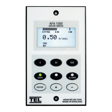
2.1 Operator Display Panel
Control output bar graph or
Alarm Time Line
Pressure display in Pa or Ins Wg
LED indicators
Function and up/down buttons
for Menu Conguration and
Calibration.
ENTER – also used as
Mute button for audible alarm
Note:
Access to the Calibration and Conguration menus is password protected
and is factory set. To access and or change the password contact the
supplier for the engineers password and enter the Passwords in the Main
Menu or alternatively use a Laptop connected to the Com port and use the
Upload/Download software provided.

Version 01 / p.11
AFA1000/BLD Pressure Controller
Installation & Operating Manual
2.2 Display Features
The Pressure Monitor display has the following features:
The digital display is a backlit, full colour high resolution graphic unit with a visual display area of
approx 45 x 34mm. The display operates through the software allowing the generation of gures,
wording and icons. The display background colour can be provided as either Blue or Black.
The display shows the static pressure in Pa or In Wg when enabled or the alternative with no
pressure reading but showing AIR FAIL / AIR SAFE as continuous display. All of the above are
congurable via the alarm key pad.
The displayed pressure colour will change when in an alarm condition:-
Air Safe = White / Low or High Air Alarm = Red / Warning Air Alarm = Amber.
An ‘event time line ’ segmented into 60 x 1 minute segments will scroll across the display (when
enabled) .This takes the form of a graphical scale ranged over 0-1.00 m/sec that will progress from the
right hand side to the left hand side of the screen – representing the airow value at each segment.
The segment colour will change if the value is in the range of an airow alarm:-
Air Safe = White / Low or High Air Alarm = Red / Warning Air Alarm = Amber.
The alternative to the event time line is a dynamic ‘bar graph’ representing the control output.
The display shows a Horn icon (with line through it) when the audible alarm is in the Muted condition.

Version 01 / p.12
AFA1000/BLD Pressure Controller
Installation & Operating Manual
2.3 Displayed Alarms and Events
Low Pressure – will be displayed when the Extract system pressure falls below the alarm
point. This display will alternate on/o with the pressure reading.
High Pressure – will be displayed when the Extract system pressure rises above the alarm
point. This display will alternate on/o with the pressure reading.
Emergency – will be displayed when the Emergency input is activated (when enabled)
This display will alternate on/o with the pressure reading
Set-back - will be displayed if the night set-back function is activated (when enabled)
This display will alternate on/o with the pressure reading
2.4 LED Indicators
The alarm unit has three LED indicators:
RED – Alarm
Amber – Caution
Green – Safe
2.5 Audible Alarm Sounder
The AFA1000/BLD has an audible sounder with local or remote mute facility. The audible alarm
can be permanently disabled in the cal cong menu.
The audible alarm is muted when the Setback input function is active.
The display will show a Mute Icon in the bottom left hand side of the screen whenever the audible
alarm is muted or disabled.
If an Input is set to the Mute function the keypad mute Enter button is disabled and the audible
alarm is only mutable using the selected Mute input.

Version 01 / p.13
AFA1000/BLD Pressure Controller
Installation & Operating Manual
2.6 Pushbuttons
a. Enter
The alarm has an Enter button -- this is multi-functional as follows:-
Press Enter momentarily when alarm is sounding will mute the alarm.
Press Enter for 5 secs will gain access to Calibration and Conguration menus (both menus
password protected).
b. +& -
The alarm has + / - buttons that can be used to scroll through the calibration and conguration
menu or to select options or values.

Version 01 / p.14
AFA1000/BLD Pressure Controller
Installation & Operating Manual
2.7 Diagnostics Menu
The AFA1000/BLD has a diagnostics menu that shows current Input and Output
status, Coms data and also includes an Alarm Test function.
To access the diagnostics menu press the ‘+’ and ‘-’ buttons together whilst in the run
screen.
The diagnostics sub menu will appear showing the following options-
a. Alarm Test
b. Coms data
c. I/O Status
d. Done
Use the +/- buttons to scroll and Enter to select the required parameter.
a. Alarm Test - the Screen will show “Testing Safe LED” and the Green Safe LED will
illuminate. The screen will then show “Testing Warning LED” and the Amber Warning
LED will illuminate. The screen will then show Testing Alarm” and the Red Alarm LED
will illuminate and the audible alarm will sound.
The screen will then return to the Diagnostics menu.
b. Coms data - the Screen will show the coms setting data for the relevant selected
protocol:-
Protocol = None/TEL/Modbus/BACnet
ID = Slave ID for Modbus or Device Instance for BACnet
Baud Rate = Shows selected Baud Rate
Parity = Shows selected Parity
Tx & Rx = the display will show the current data packets sent and received, the
displayed value will rollover to zero when the maximum count is reached.
c. I/O Status - when selected the following options are shown:-
Input Data
Output Data
Sensor Data
Done

Version 01 / p.15
AFA1000/BLD Pressure Controller
Installation & Operating Manual
Input Data:-
Input 1 - 0 / O / On / Not Used
Input 2 - 0 / O / On / Not Used
Input 3 - 0 / O / On / Not Used
O = Input Open
On = Input Closed
Not Used = Input not assigned
Output Data:-
Output 1 - O / On A Out 1 - 10.0
Output 2 - O / On A Out 2 - 10.0
Output 3 - O / On
Output O = Output Open or not assigned
Output On = Output Closed
A Out 1 = Analogue Output 1 voltage (0-10VDC)
A Out 2 = Analogue Output 2 voltage (0-10VDC)
Sensor Data:-
Pressure 00.0 %
Pressure % = Output of Pressure sensor in %, 0% = no Pressure
Done - returns to Diagnostics menu.
d. Done - when selected the monitor returns to the run screen.

Version 01 / p.16
AFA1000/BLD Pressure Controller
Installation & Operating Manual
2.8 External Connections
The AFA1000/BLD has the following Inputs:-
Setback Input
Volt free input congurable for normally closed, normally open relays.
Emergency Input
Volt free input congurable for normally closed, normally open relays.
Pressure Sensor Input
Analogue input (0-5V) of the pressure sensor range (selectable on the pressure transducer)
Relay Output 1
Analogue input (0-5V) of the pressure sensor range (selectable on the pressure transducer)
Relay Output 2
Volt free relay output congurable as normally closed or normally open relays.
Relay Output 3
Volt free relay output congurable as normally closed or normally open relays.
Pressure Output 1
0-10VDC / 2-10VDC control output – congurable for direct or indirect action.
Pressure Output 2 (optional)
Retransmission of pressure output 1.

Version 01 / p.17
AFA1000/BLD Pressure Controller
Installation & Operating Manual
Sensor Output
0-5VDC retransmission of pressure reading.
Com Port
RS 485 to enable connection to Laptop or PC for full diagnostics, logging or setting up and for
communications to building computer system (BMS)
See section 8 for other specic information on Modbus RTU and BACnet options and settings.
Power supply
Low voltage DC power supply from PCB power supply (damper control type) or Mains power
adaptor.

3. FUNCTIONS & OPERATION

Version 01 / p.19
AFA1000/BLD Pressure Controller
Installation & Operating Manual
3.1 Pressure Functions
The AFA1000/BLD Pressure display can be set up using the pushbutton menus to display
airow in units of m/sec or fpm and can also be set to show plain text “Air Safe” & “Air Fail”
only
TheAFA1000/BLDhas3programmableairowalarms.
Safe pressure
• Display reading above Low pressure alarm level and below High pressure alarm level
• Green LED on
Warning pressure
• Display reading below Warning level and above Low pressure alarm level
• Amber LED on
Low pressure
• Meter reads below Low pressure alarm level for longer than the delay time
• LOW PRES. toggles on / o with display
• Red LED on ( Flashing )
• Audible alarm sounds -- can be muted via Enter pushbutton
• Low pressure relay operates ( if congured )
Reset: -- when pressure rises above Low pressure alarm level (including pre-set hysteresis)
the Low pressure alarm resets automatically
High pressure
If congured:
• Meter reads above high pressure alarm level for longer than the delay time
• HIGH PRES toggles on / o with display
• Audible alarm sounds – can be muted via Enter pushbutton.
Reset: -- when pressure falls below High pressure alarm level (including pre-set hysteresis)
the High pressure alarm resets automatically
3 FUNCTIONS & OPERATION

Version 01 / p.20
AFA1000/BLD Pressure Controller
Installation & Operating Manual
3.2 Input Functions
Night set-back
• When input congured as Night set-back is activated
• Night SETBACK Icon toggles on / o with display
• Unit is driven to the pre-determined MIN position depending on Control function
selected (see below)
Night set-back mute
• Audible alarm muted Mute Icon shown on display (when enabled)
Emergency
• When input congured as Emergency is activated
• Red LED on ( Flashing) – ( if congured )
• EMERGENCY toggles on /o with display -- ( if congured )
• Audible alarm sounds – can be muted via Enter pushbutton
• Emergency alarm relay operates ( if congured)
• Unit is driven to the pre-determined MAX position depending on Control function
selected ( see below )
Note:- The external Emergency input can be a remote relay contact or a local
Emergency Stop stay-put pushbutton.
Audible alarm Mute
When the audible alarm is muted via the Enter button – an Icon (horn with forward
slash) is shown on the display.
Table of contents
Other TEL Controllers manuals
Popular Controllers manuals by other brands
Control Technology Inc.
Control Technology Inc. 2500 Series Installation and operation guide
Wibre
Wibre 5.0670.19.24 installation manual
Beckhoff
Beckhoff BK7300 user manual
Grundfos
Grundfos CU 3x4 Installation and operating instructions
Enttec
Enttec Pixelator user manual
EG&G
EG&G ORTEC 403A instruction manual
