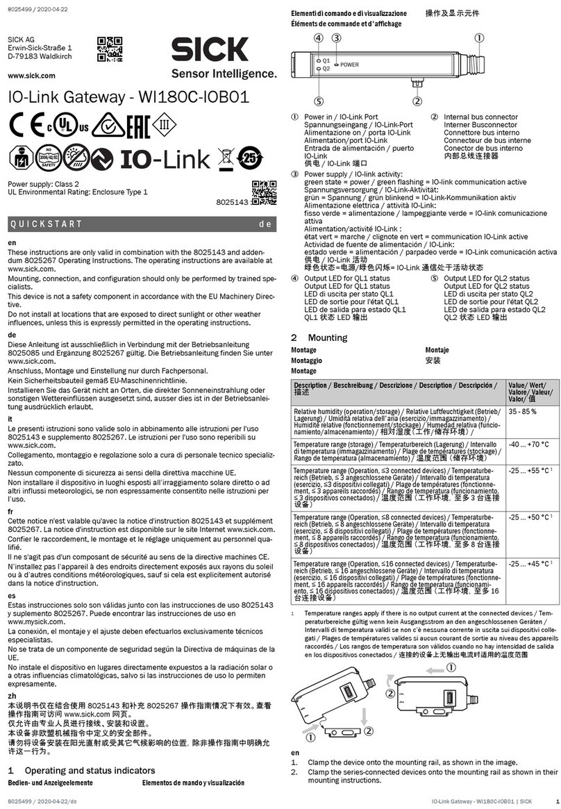
SICK TDC-E User manual

OPERATING INSTRUCTIONS
TDC-E (Telematic Data Collector)
Gateway systems

2
8027311 / V1-0/2022-04|SICK
OPERATING INSTRUCTIONS|TDC-E (Telematic Data Collector)
Subject to change without notice
Described product
TDC-E (Telematic Data Collector)
Document no.
8027311
Manufacturer
SICK AG
Erwin-Sick-Str. 1 · 79183 Waldkirch · Germany
www.sick.com
Legal notes
This work is protected by copyright. The associated rights are reserved by SICK AG.
Reproduction of this document or parts of this document is only permissible within
the limits of the legal provisions of copyright law. Any modification, abridgment, or
translation of this document is prohibited without the express written permission of
SICK AG.
The trademarks mentioned in this document are the property of their respective
owners.
© SICK. All rights reserved
Original documents
This document is a translation of an original document of SICK AG.

CONTENT
3
8027311 / V1-0/2022-04|SICK
Subject to change without notice
OPERATING INSTRUCTIONS|TDC-E (Telematic Data Collector)
Content
1About this document......................................................................................................6
1.1 Limitation of liability .............................................................................................6
1.2 Purpose of this document....................................................................................6
1.3 Target groups........................................................................................................7
1.4 Abbreviations used...............................................................................................7
1.5 Further information ..............................................................................................8
1.6 Document conventions ........................................................................................8
2For your safety................................................................................................................9
2.1 Intended use.........................................................................................................9
2.2 General safety notes ............................................................................................9
2.3 Requirements for the qualification of personnel ............................................ 10
2.4 Warranty ............................................................................................................ 10
2.5 RoHS Directive................................................................................................... 10
2.6 Safety conventions............................................................................................ 10
2.7 Sources of danger ............................................................................................. 11
2.8 Warning symbols on the system components................................................. 11
2.9 Mandatory symbols ........................................................................................... 11
3System description ..................................................................................................... 12
3.1 Scope of delivery ............................................................................................... 12
3.2 Data collection................................................................................................... 14
3.3 Data processing ................................................................................................ 15
3.4 Data transmission ............................................................................................. 16
3.5 Status display on the TDC-E ............................................................................. 19
4Mounting ..................................................................................................................... 20
4.1 Inserting SIM card ............................................................................................. 20
4.2 Mounting device................................................................................................ 21
4.2.1 Mounting on a plate........................................................................... 21
4.2.2 Mounting on DIN mounting rails ....................................................... 22
5Electrical installation ................................................................................................. 24
5.1 Connection overview of TDC-E.......................................................................... 25
5.2 Connector .......................................................................................................... 26
5.3 Connecting the voltage supply ......................................................................... 27
5.4 Connecting antennas........................................................................................ 28
6Configuration............................................................................................................... 29
6.1 Preparing for configuration............................................................................... 29
6.2 Initial registration .............................................................................................. 30
6.2.1 Creating initial user............................................................................ 30
6.2.2 Performing registration...................................................................... 31
6.2.3 Home page ......................................................................................... 31
7Configuration of the device settings ......................................................................... 32
7.1 The Device Manager ......................................................................................... 32
7.2 System settings ................................................................................................. 33
7.2.1 System ................................................................................................ 33
7.2.2 Maintenance ...................................................................................... 34
7.2.3 Firmware............................................................................................. 37
7.2.4 Time .................................................................................................... 38
7.2.5 Logs..................................................................................................... 39
CONTENT
4
8027311 / V1-0/2022-04|SICK
OPERATING INSTRUCTIONS|TDC-E (Telematic Data Collector)
Subject to change without notice
7.3 Network settings ................................................................................................40
7.3.1 Network ...............................................................................................40
7.3.2 Segments ............................................................................................40
7.3.3 LAN ......................................................................................................44
7.3.4 WLAN ...................................................................................................45
7.3.5 modem ................................................................................................48
7.3.6 DNS......................................................................................................50
7.3.7 Tools ....................................................................................................51
7.4 Security settings.................................................................................................52
7.4.1 Security................................................................................................52
7.4.2 Certificates ..........................................................................................52
7.4.3 Logs .....................................................................................................54
7.4.4 Help .....................................................................................................55
7.4.5 Licenses ..............................................................................................55
7.5 User management in Device Manager .............................................................56
7.5.1 Creating users.....................................................................................56
7.5.2 Assigning user role .............................................................................57
7.5.3 Editing user .........................................................................................58
7.6 Use REST API interface for Device Manager ....................................................59
7.6.1 Calling up Swagger .............................................................................59
7.6.2 Authenticating access to Device Manager API interface..................59
7.6.3 Generating request in Swagger..........................................................60
8Configuring the connection settings .........................................................................62
8.1 The Interface Manager ......................................................................................62
8.1.1 Starting Interface Manager ................................................................62
8.1.2 Interface Manager user interface ......................................................62
8.1.3 Authenticating access to interface parameters................................64
8.1.4 Editing mode .......................................................................................64
8.2 Data collection interfaces..................................................................................67
8.2.1 Motion sensor .....................................................................................67
8.2.2 Analog inputs ......................................................................................68
8.2.3 CAN interface ......................................................................................70
8.2.4 Digital inputs and outputs ..................................................................72
8.2.5 GPS ......................................................................................................74
8.2.6 LED management ...............................................................................75
8.2.7 Position sensor ...................................................................................76
8.2.8 OneWire...............................................................................................78
8.2.9 Serial interfaces..................................................................................79
8.2.10 SSI........................................................................................................81
8.3 Interfaces for data transmission.......................................................................82
8.3.1 Configuration of the WebSocket interface ........................................82
8.3.2 Configuration of the MQTT interface..................................................83
8.4 Saving the configuration....................................................................................85
8.5 Downloading log files.........................................................................................85
8.6 User management in the Interface Manager ...................................................87
8.6.1 Changing default passwords..............................................................87
8.6.2 Creating users.....................................................................................88
8.6.3 Changing user password ....................................................................89

CONTENT
5
8027311 / V1-0/2022-04|SICK
Subject to change without notice
OPERATING INSTRUCTIONS|TDC-E (Telematic Data Collector)
9Docker container management ................................................................................. 90
9.1 The Portainer ..................................................................................................... 90
9.1.1 Starting Portainer............................................................................... 90
9.1.2 Creating initial user............................................................................ 90
9.1.3 Portainer user interface..................................................................... 91
9.2 Implementing application ................................................................................. 92
9.3 User management in the Portainer.................................................................. 95
10 Maintenance and repair ............................................................................................. 96
10.1 Maintenance during operation......................................................................... 96
10.2 Replacing a TDC-E ............................................................................................. 96
11 Technical data............................................................................................................. 97
11.1 Technical data ................................................................................................... 97
11.1.1 TDC-E .................................................................................................. 97
11.1.2 Internal sensors ............................................................................... 100
11.2 Dimensional drawings..................................................................................... 101
11.3 TDC-E pin assignments ................................................................................... 102
12 Disposal ..................................................................................................................... 104

1ABOUT THIS DOCUMENT
6
8027311 / V1-0/2022-04|SICK
OPERATING INSTRUCTIONS|TDC-E (Telematic Data Collector)
Subject to change without notice
1About this document
These supplementary operating instructions for the TDC-E (Telematic Data Collector)
gateway system:
•Contains information that is required during the life cycle of the system.
•Must be available to all those who work with the system.
•Should be read through carefully, and the contents fully understood before working
with the system.
1.1 Limitation of liability
Applicable standards and regulations, the latest technological developments, and
our many years of knowledge and experience have all been taken into account when
assembling the data and information contained in this document.
The manufacturer accepts no liability for damage caused by:
•Failure to observe this document.
•Non-compliance with notes and regulations.
•Unauthorized mounting and installation.
•Unauthorized technical and other changes.
•Use of unauthorized spare parts, wear and tear parts, and accessories.
•Unauthorized changes, adjustments, and/or manipulations of software.
•Failure to perform and document regular maintenance work.
The actual scope of delivery may differ from the features and illustrations shown here
where special variants are involved, if optional extras have been ordered, or as a result of
the latest technical changes.
1.2 Purpose of this document
These operating instructions are designed to give technical personnel instructions on the
safe mounting, parameterization, electrical installation, commissioning, operation, and
maintenance of the gateway system.
These operating instructions do not provide information on how to operate vehicles or
machines into which the individual devices of the gateway system have been or are going
to be integrated. More information on this can be found in the customer documentation.

ABOUT THIS DOCUMENT 1
7
8027311 / V1-0/2022-04|SICK
Subject to change without notice
OPERATING INSTRUCTIONS|TDC-E (Telematic Data Collector)
1.3 Target groups
These operating instructions are intended for people integrating the devices of the
gateway system into a vehicle or machine, and people performing initial commissioning,
operation, and maintenance.
1.4 Abbreviations used
Application Programming Interface
Access Point Name = network operator’s point of access to the GPRS data network
Controller Area Network = serial bus system
Long-term evolution = technical radio standard for digital radio telephony
General Packet Radio Service = the name of the packet-based service for transmitting
data over GSM networks
Global Positioning System = global navigation satellite system used for position
determination
Local Area Network
Message Queue Telemetry Transport = open messaging protocol for transmitting
telemetry data between devices in the form of messages
Subscriber identity module = chip card for cell phones
Telematic Data Collector = system for collecting, processing and transmitting telemetry
data
Wireless Local Area Network
API
APN
CAN bus
LTE
GPRS
GPS
LAN
MQTT
SIM
TDC
WLAN

1ABOUT THIS DOCUMENT
8
8027311 / V1-0/2022-04|SICK
OPERATING INSTRUCTIONS|TDC-E (Telematic Data Collector)
Subject to change without notice
1.5 Further information
Special local conditions
▸The local laws, regulations, technical rules and internal company operating instructions
at the installation location must be observed.
Storage of documents
This document and other relevant technical documentation/information:
•Must be kept available for reference.
•Must be handed over to new system operators/new specialist personnel.
1.6 Document conventions
▸Instructions
Result of action
All measurement units used in this document are metric.
Subject to change without notice.
Figures may differ from the actual design.

FOR YOUR SAFETY 2
9
8027311 / V1-0/2022-04|SICK
Subject to change without notice
OPERATING INSTRUCTIONS|TDC-E (Telematic Data Collector)
2For your safety
2.1 Intended use
The TDC-E gateway system is a system that receives and processes sensor data, and
then forwards this data to a higher-level infrastructure (cloud server or local server).
System functions can be extended by adding customized applications using the
microservices architecture.
Consequently, the TDC-E is designed for sensor-controlled monitoring tasks, vehicle
tracking, working time management, and access control, or for telemetry applications.
The gateway system uses one or more TDC-E devices to collect data. The devices
feature all the standard interfaces for integrating sensors.
The sensor data received can be transmitted to the cloud via the mobile network or via
a WLAN connection. In addition to the MQTT transmission protocol, WebSocket is also
supported. In addition, access to sensor data is possible via the integrated REST API
interface.
NOTE! Intended use also includes observance of this addendum, in particular the safety
notes as well as the repair and maintenance requirements.
2.2 General safety notes
▸Please read this document through carefully and observe all the safety notes and
information before working with the TDC-E.
▸Only qualified persons from the relevant departments are permitted to work on the
TDC-E.
▸Follow operating processes.
▸Follow local regulations.
▸Follow all local regulations relating to working with electrical components.
•Only authorized persons are permitted access to the TDC-E.
System damage/transport damage
Damage to the individual components can lead to malfunctions of the system as a whole.
▸Do not ignore any damage caused to system components during transport.
▸In case of damage, contact SICK Service.

2FOR YOUR SAFETY
10
8027311 / V1-0/2022-04|SICK
OPERATING INSTRUCTIONS|TDC-E (Telematic Data Collector)
Subject to change without notice
2.3 Requirements for the qualification of personnel
Only qualified persons with the relevant technical expertise are permitted to work on
the TDC-E.
•Qualified persons have the specialist training, skills, and experience, as well as
knowledge of the relevant regulations and standards, to be able to perform work
assigned to them and to identify and avoid any potential dangers independently.
•Electricians have the professional training, skills and experience, and knowledge of
the relevant standards and provisions to work on electrical systems and to detect
and avoid any potential dangers independently.
2.4 Warranty
No warranty claims will be accepted if:
▸The safety notes and measures in this document are not observed.
▸Parts or components of the TDC-E have been installed, mounted or modified without
authorization.
▸The software has been modified, customized, and/or tampered with without
authorization.
2.5 RoHS Directive
This product has been designed for specific applications in industrial environments
according to Article 2 (4) e, RoHS 2011/65 / EU, and must therefore only be used in such
environments.
The product is neither suitable nor approved for use outside of these environments. SICK
therefore cannot provide any warranty or accept any liability whatsoever for such use.
2.6 Safety conventions
The warnings used in these supplementary operating instructions have the following
meanings:
DANGER
Identifies an imminent danger, which will lead to death or serious injuries if not
prevented.
WARNING
Identifies a situation presenting danger, which will lead to death or serious injuries if
not prevented.
CAUTION
Identifies a possibly hazardous situation which may lead to minor or moderate bodily
injuries or material damage if not prevented.
NOTE Important information and useful notes.

FOR YOUR SAFETY 2
11
8027311 / V1-0/2022-04|SICK
Subject to change without notice
OPERATING INSTRUCTIONS|TDC-E (Telematic Data Collector)
2.7 Sources of danger
The TDC-E gateway system is designed in a way that allows for safe operation. Protective
devices reduce potential risks to the maximum possible extent.
DANGER!
RISK OF INJURY DUE TO ELECTRICAL CURRENT
The TDC-E is connected to an external voltage source.
Touching live devices, which may still be energized, can lead to death, burns or
electrical shock.
▸Only qualified specialist personnel are permitted to perform electrical work on the
driver assistance system.
▸Before working on electrical components, observe the five safety rules:
▸Disconnect.
▸Secure against being switched back on.
▸Ensure that there is no voltage.
▸Ground and short-circuit.
▸
Cover or enclose live parts in the vicinity.
2.8 Warning symbols on the system components
Warning labels must not be removed or covered up. If labels are missing, these must be
affixed. Damaged labels must be replaced.
Symbol Meaning
Hazardous point warning
Hazardous electrical voltage warning
2.9 Mandatory symbols
Symbol Meaning
Read document
Disconnect before maintenance or repairs

3SYSTEM DESCRIPTION
12
8027311 / V1-0/2022-04|SICK
OPERATING INSTRUCTIONS|TDC-E (Telematic Data Collector)
Subject to change without notice
3System description
3.1 Scope of delivery
NOTE!
▸After delivery, inspect the system for transport damage and report any such damage
immediately.
▸Check that the delivery includes all components listed on the delivery note.
Fig. 1: System components
Legend
1 TDC-E
2 WLAN antenna
3 LTE antenna
4 GPS antenna
5 Voltage supply cable
6 Quickstart
Quantity Part no. Description
n 6070344
or
6079357
TDC-E210xx
n 6074432 WLAN antenna
n 6077804 LTE antenna
n 6067023 GPS antenna, 3 m
n 6068473 Voltage supply cable, 0.9 m
n 8022507 Quickstart guide including download link for the operating
instructions, system documentation, and interface descriptions

SYSTEM DESCRIPTION 3
13
8027311 / V1-0/2022-04|SICK
Subject to change without notice
OPERATING INSTRUCTIONS|TDC-E (Telematic Data Collector)
Fig. 2: Accessories (optional)
Legend
1 14-Pin Micro-Fit male connector
2 20-pin Micro-Fit male connector
3 DIN rail bracket
Preassembled cables can be purchased for connecting the sensors to the TDC-E devices.
Part no. Description
6068472 14-Pin Micro-Fit male connector with 14 color-coded wires with open
ends, length 90 cm.
Enables the connection of:
•Voltage supply (2 wires)
•Digital inputs and outputs
•Analog inputs
6068471 20-pin Micro-Fit male connector with 20 color-coded wires with open
ends, length 90 cm
Enables the connection of:
•Additional digital inputs and outputs
•RS-485/422, RS-232, SSI, 1-wire serial interfaces
•CAN
Tab. 1: Additional connecting cables (optional) – part numbers
A rail bracket is available for mounting the TDC-E on DIN mounting rails.
Part no. Description
6069266 DIN rail bracket for mounting the TDC-E
Tab. 2: DIN mounting rail bracket (optional)
Accessories (optional)

3SYSTEM DESCRIPTION
14
8027311 / V1-0/2022-04|SICK
OPERATING INSTRUCTIONS|TDC-E (Telematic Data Collector)
Subject to change without notice
3.2 Data collection
Fig. 3: Data collection
Legend
1 External sensors
2 Machine data
3 Transmission via I/O, serial interfaces, Ethernet and CAN, among others
4 Integrated sensors
•The TDC-E can be used to collect sensor data and sensor events. When functioning
in this capacity, it offers all the standard interfaces required to integrate sensors,
machines, and devices.
•Digital, analog, CAN bus-based, serial and Ethernet-based and other signals can be
processed and aggregated.
•These external sensor data are supplemented by data from the TDC-E’s factory-
installed movement, position, and temperature sensors.
•The TDC-E also allows for the connection of a GPS antenna.
•This can be used for outdoor localization.
•The TDC-E motion data is processed together with the received GPS data.
Function
GPS

SYSTEM DESCRIPTION 3
15
8027311 / V1-0/2022-04|SICK
Subject to change without notice
OPERATING INSTRUCTIONS|TDC-E (Telematic Data Collector)
3.3 Data processing
Fig. 4: Data processing
•The merged data is filtered and simple evaluations, such as diagnostics of limit value
overshoots, can be done.
•Pre-processing can reduce response time and transmission costs.
•Data processing is performed via applications that can be quickly implemented using
the TDC-E microservice architecture.
•Node-Red, for example, is a graphical development tool developed by IBM. The
software makes it possible to implement use cases for the Internet of Things with a
simple modular principle. The individual function blocks are related to each other by
dragging connections.
Fig. 5: Docker container
Legend
1 Arm processor
2 Linux operating system
3 Docker
4 Container with application
Function
Docker container

3SYSTEM DESCRIPTION
16
8027311 / V1-0/2022-04|SICK
OPERATING INSTRUCTIONS|TDC-E (Telematic Data Collector)
Subject to change without notice
•The Docker technology uses the Linux kernel and its features to isolate processes
so they can run independently.
•Docker is a tool that makes it easier to deploy and execute applications by using
containers.
•A container does not just hold the application itself but also all of the resources
required by the application during runtime.
•Thanks to the container technology, the gateway system can be rapidly extended by
adding customer-specific applications.
3.4 Data transmission
Fig. 6: Data transmission
•The sensor data can be transmitted to a customer server either via LAN, WLAN or
mobile radio.
•Data is usually transferred via the MQTT protocol or the WebSocket protocol.
•Access to the device information and device configurations is also possible via the
REST API interface integrated in the TDC-E.
Ways of data
transmission

SYSTEM DESCRIPTION 3
17
8027311 / V1-0/2022-04|SICK
Subject to change without notice
OPERATING INSTRUCTIONS|TDC-E (Telematic Data Collector)
Fig. 7: MQTT protocol
Legend
A MQTT client
B MQTT message broker
C MQTT client
1 Provides topics (publish)
2 Subscribes to topics (subscribe)
•MQTT is a client-server protocol that follows the publish/subscribe principle.
•Clients send messages with a topic to the MQTT message broker after the connection
is established, which classifies the message hierarchically (e.g. “TDC-E temperature
sensor/temperature”).
•Messages always consist of a topic and the message content.
•Clients can subscribe to these topics, with the MQTT message broker forwarding the
received messages to the appropriate subscribers.
•It is the TDC-E that assumes the publisher role within the gateway system.
•It uses the MQTT protocol to send topics containing sensor data within a defined
structure.
•The client server is the subscriber of this data.
•Thanks to the defined topic structure, this service is able to retrieve the messages and
continue to process them.
MQTT

3SYSTEM DESCRIPTION
18
8027311 / V1-0/2022-04|SICK
OPERATING INSTRUCTIONS|TDC-E (Telematic Data Collector)
Subject to change without notice
Fig. 8: WebSocket protocol
Legend
A Client
B WebSocket server
1 Initial handshake between client and server
2 Constantly open connection for bidirectional message transmission
•WebSocket is a TCP/IP protocol that provides a constant open connection after an
initial WebSocket handshake between a client and a WebSocket server.
•A WebSocket server is nothing more than an application that monitors a port of a
TCP/IP server that follows a specific protocol.
•The WebSocket server is installed by the customer.
•The WebSocket server can actively use the open connection and retrieve information
from the client without any previous requests.
•The TDC-E has the role of data provider.
WebSocket

SYSTEM DESCRIPTION 3
19
8027311 / V1-0/2022-04|SICK
Subject to change without notice
OPERATING INSTRUCTIONS|TDC-E (Telematic Data Collector)
3.5 Status display on the TDC-E
The TDC-E has three 3 status LEDs each, which indicate the current operational status.
Fig. 9: Status display on the TDC-E
Status Green LED Yellow LED Red LED
Authentication
before booting
ON OFF OFF
Booting Fast flashing OFF OFF
Device ready for
operation
Heartbeat flashing OFF OFF
Restoration of backup Fast flashing Fast flashing OFF
Device reset
(factory, data or
system reset)
Fast flashing Fast flashing OFF
Software update Fast flashing Fast flashing OFF
User defined via
Interface Manager
OFF ON/OFF
heartbeat flashing
ON/OFF
heartbeat flashing
Tab. 3: Status display on the TDC-E

4MOUNTING
20
8027311 / V1-0/2022-04|SICK
OPERATING INSTRUCTIONS|TDC-E (Telematic Data Collector)
Subject to change without notice
4Mounting
All transport, assembly, mounting, and electrical installation work must only be carried out
by qualified persons.
Qualified persons have the specialist training, skills, experience and knowledge of the
relevant regulations and standards needed to be able to perform work assigned to them
and to identify and avoid any potential dangers independently.
▸If possible, the TDC-E should be mounted close to the battery so it can be connected to
the voltage supply or close to the electrical installation so that the peripheral devices
can be connected.
▸Select the mounting location so that the TDC-E is protected from dirt and mechanical
damage.
4.1 Inserting SIM card
The SIM card of the telecommunications provider must be inserted by the customer.
▸NOTE Only use M2M SIM cards without PIN.
CAUTION!
RISK OF DEVICE DAMAGE
▸
Only insert the SIM card when the device is switched off.
▸Make sure that the device is switched off.
▸Unscrew the plastic cover on the bottom of the device and remove it.
Fig. 10: Removing plastic cover
▸Slide the plastic cover of the SIM card holder to one side. There is an indicator arrow on
the holder.
Fig. 11: Sliding the cover of the SIM card holder to the side
Notes on
mounting
Note
Mounting
Table of contents
Other SICK Gateway manuals

SICK
SICK SIG200 User manual

SICK
SICK EFI Manual

SICK
SICK SIG200 User manual

SICK
SICK Flexi Soft User manual

SICK
SICK RFU63x User manual

SICK
SICK WI180C-IOB01 User manual

SICK
SICK SIG200 User manual

SICK
SICK Flexi Classic User manual

SICK
SICK EtherNet/IP SIG350 User manual

SICK
SICK Flexi Gateway GCAN1 User manual