iRZ ES75iT User manual


2
Contents
1.Introduction............................................................................................................................. 4
1.1.Document description..................................................................................................................... 4
1.2.Service data................................................................................................................................... 4
1.3.Safety rules.................................................................................................................................... 4
2.General Information................................................................................................................ 5
2.1.Purpose.......................................................................................................................................... 5
2.2.Set ................................................................................................................................................. 5
2.3.Features......................................................................................................................................... 5
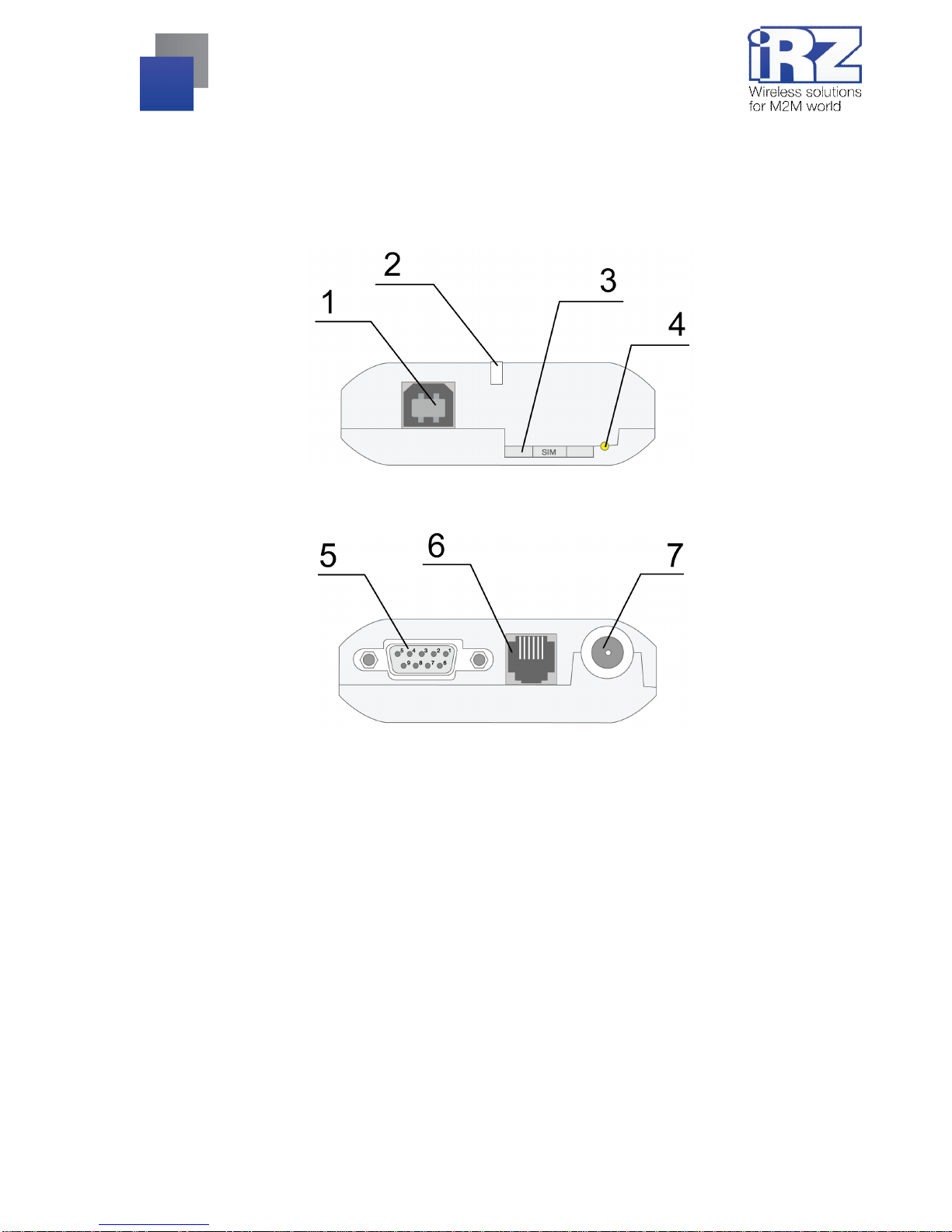
2.4.Appearance.................................................................................................................................... 7
2.5.Interfaces....................................................................................................................................... 8
2.5.1. DB9 connector for connecting the communication cable.......................................................... 8
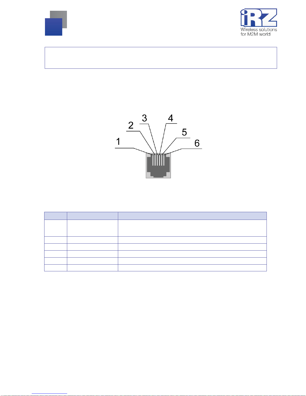
2.5.2. TJ6-6P6C power connector..................................................................................................... 9
2.5.3. USB type B connector........................................................................................................... 10
2.6.Modem status display................................................................................................................... 11
3.Connecting and configuring................................................................................................. 12
3.1.Connecting................................................................................................................................... 12
3.2.Control, rebooting, shutdown........................................................................................................ 12
3.3.Types of watchdog timers............................................................................................................. 13
3.4.Menu mode .................................................................................................................................. 13
3.5.Programming mode...................................................................................................................... 16
4.Emergencies.......................................................................................................................... 19
4.1.Emergency 1 (incorrect input power supply).................................................................................. 19
4.2.Emergency 2 (incorrect module power supply).............................................................................. 19
4.3.Emergency 3 (GSM module failed to start).................................................................................... 19
4.4.Emergency 4 (COM-port not ready).............................................................................................. 19
5.Support.................................................................................................................................. 20

3
Tables
Table 2.5.1: Using DB9 connector pins..............................................................................................8
Table 2.5.2: Using connector power pins........................................................................................... 9
Table 2.5.3: Using USB connector pins ...........................................................................................10
Table 2.6.1: Operation mode display (green LED)........................................................................... 11
Table 2.6.2: Emergency display (red LED) ......................................................................................11
Figures
Fig. 2.4.1. Front view......................................................................................................................... 7
Fig. 2.4.2. Back view.......................................................................................................................... 7
Fig. 2.5.1. DB9 connector..................................................................................................................8
Fig. 2.5.3. Power connector...............................................................................................................9
Fig. 2.5.4. USB connector type B.....................................................................................................10
Fig. 3.1. Main view...........................................................................................................................16
Fig. 3.2. Port opening....................................................................................................................... 17
Fig. 3.3. File uploading.....................................................................................................................17
Fig. 3.4. File is uploaded.................................................................................................................. 17
Fig. 3.5. Flash-memory writing.........................................................................................................18
Fig. 3.6. Exiting program mode........................................................................................................18

4
1. Introduction
1.1. Document description
This manual is intended for experienced PC users. It describes the device and the operation of the GSM
modem iRZ ES75iT.
1.2. Service data
Document version Issue date
2.2 10.17.2013
Prepared by V.N. Golovin Approved by P.A. Kosolapov
1.3. Safety rules
Restrictions on the use of the device near other electronic devices:
Turn the modem off in hospitals or when located near medical equipment such as pacemakers, hearing
aids and so on. Interference for medical equipment may occur;
Turn the terminal off when on an airplane. Take measures to avoid accidental turning on;
Turn the modem off in the vicinity of gas stations, chemical plants, and places where demolition work is
conducted. Interference for technical devices may occur;
At a close range, the modem may produce interference for television sets and radio transmitters.
Maintenance requirements:
Protect the modem against external hazards (high temperatures, caustic chemicals, dust, water and so
on);
Keep the modem safe from blows, falls, and strong vibrations;
Do not attempt to take apart or modify the modem on your own. Such actions will void your warranty.
Note: Make sure you follow the operation manual for this device. Improper use of the device will disqualify
your warranty.

5
2. General Information
2.1. Purpose
ES75iT is an industrial GSM modem for receiving and transmitting data through a GSM channel (EDGE,
GPRS). It is perfectly suited both for providing mobile access to the Internet and for industrial applications
including telemetry, wireless data collection from sensors, remote monitoring, control, and signaling.
The modem is equipped with a watchdog timer, which allows for an unconditional reboot of the equipment
after a specified period of time. The modem is controlled by standard AT-commands and also possesses its
own range of control commands. The device is equipped with LEDs to monitor connection status and signal for
emergency.
2.2. Set
The set of the GSM modem ES75iT includes:
ES75iT terminal;
Factory package;
2.3. Features
Key features:
Frequency ranges: GSM 850/900/1800/1900MHz;
Output power:
2W (class 4 for EGSM850/900);
1W (class 1 for GSM1800/1900);
EDGE class 12;
GPRS class 12;
MS class B;
CSD up to 14.4 kbps;
USSD;
SMS: MT, MO, CB, Text and PDU modes;
Fax group 3, class 1;
Power:
Power supply from 9 to 30V;
Consumption current not exceeding:
with the supply voltage of +12V - 200mA;
with the supply voltage of +24V - 100mA;

6
Physical characteristics:
Dimensions not exceeding 70х74х33 mm;
Weight not exceeding 105g;
Operating temperatures from -30°Сto +60°С;
Interfaces:
DB9-F connector for connecting the communication cable with RS232 interface;
USB type B connector for connecting the communication cable with USB 2.0 interface;
FME Jack (male) for connecting the GSM antenna;
TJ6-6P6C for RJ12 power connector for powering the modem.

7
2.4. Appearance
Terminal ES75iT is a compact device in a durable and light case. Its appearance is displayed on Fig. 2.4.1
and Fig. 2.4.2.
Fig. 2.4.1. Front view
Fig. 2.4.2. Back view
The numbers on Fig. 2.4.1 and Fig. 2.4.2 stand for:
1. USB-B connector for connecting the communication cable with USB 2.0 interface;
2. LED;
3. SIM-card tray;
4. SIM-card tray eject button;
5. DB9-F connector for connecting the communication cable with RS232 interface;
6. TJ6-6P6C power connector;
7. FME Jack (male) for connecting the GSM antenna;

8
2.5. Interfaces
2.5.1. DB9 connector for connecting the communication cable
This connector is used for connecting to the control device using the RS232 exchange protocol (for service
mode only). Factory settings of the port: speed 115200Kbit/s, 8 bits of data, no parity, stop bit – 1. The AT-
commands are used to control the modem operation (see the module description). The appearance of the
connector is displayed on Fig. 2.5.1:
Fig. 2.5.1. DB9 connector
Table 2.5.1: Using DB9 connector pins
Pins Signal Direction Purpose
1 DCD Modem-PC Presence of the carrier
2 RXD Modem-PC Data reception
3 TXD PC-Modem Data transmission
4 DTR PC-Modem Readiness for data reception
5 GND General Ground
6 DSR Modem-PC Data readiness
7 RTS PC-Modem Request to transmit
8 CTS Modem-PC Readiness for data transmission
9 RI Modem-PC Call signal
The purpose of pins is consistent with the serial interface with V.24 protocol.
The length of the cable is not to exceed 1.8 m. It is recommended to set data transfer speed that does not
exceed 115200 bit/s.

9
Attention: RS232 standard (COM-port) does not support a "hot" connection.
To avoid damaging the COM-port of the modem connect and disconnect the device at least 5 seconds after
the power of the connecting devices has been turned off.
2.5.2. TJ6-6P6C power connector
The connector is used to power the device and reset the module. Its appearance is displayed on Fig. 2.5.2.
Fig. 2.5.2. Power connector
Table 2.5.2: Using connector power pins
Contact
Signal Purpose
1 + 12V The positive pole of DC supply voltage. Fused circuit and overvoltage
protection (when applied to the input voltage of over 30V) and reverse
polarity
2 Not used
3 Not used
4 Not used
5 Not used
6 GND Ground

10
2.5.3. USB type B connector
The connector is used to connect to the control device using USB 2.0 interface. Its appearance is displayed
on Fig. 2.5.3.
Fig. 2.5.3. USB connector type B
Table 2.5.3: Using USB connector pins
Contact
Signal Purpose
1 V BUS +5V (used as input to determine USB connection)
2 D− Data transmission
3 D+ Data transmission
4 GND Ground

11
2.6. Modem status display
Two LEDs indicate current working mode (connection status) or signal for an emergency. This function may
be disabled by the following AT-command: AT^SSYNC (AT^SSYNC=1 — on; AT^SSYNC=0 — off). By default,
AT^SSYNC=1.
Table 2.6.1: Operation mode display (green LED)
Display mode Conventional indication
display Operation mode
Turned off ○Modem is turned off or is in the emergency status
600ms on / 600ms off ●●●●●●○○○○○○ Modem has not been registered online
75ms on / 3s off ●○○○○○○○○○...○Modem has been registered online
75ms on / 75ms off / 75ms on /
3s off
●○●○○○○○○○...○GPRS/EDGE connection has been established
500ms on/ 50ms off ●●●●●○Data transmission under way
250ms on / 10s off ●●●○○○○○○○...○Modem is in the sleep mode, the alarm mode
250ms on / 250ms off ●●●○○○ Programming mode, menu mode
Permanently turned on ●Voice call, CSD
Configurations of display mode with "AT^SSYNC=2" and "AT^SSYNC=1" is differ only by power saving
mode. For more information, see GSM module documentation.
Table 2.6.2: Emergency display (red LED)
Display mode Conventional indication display Emergency description
Permanently turned on ●Invalid input voltage
0.5s on / 0.5s off ●●○○ Invalid module power supply
0.25s on / 0.25s off / 0.25s on/
1s off
●○●○○○○ GSM module has not turned on
0.25 s on / 0.25 s off
/ 0.25s on / 0.25s off / 0.25s on
/ 1s off
●○●○●○○○○ COM-port is not ready
For descriptions of emergency situations see Part 4.

12
3. Connecting and configuring
3.1. Connecting
Only individuals with specialized technical training and who have studied the product specifications are
permitted to assemble (install) the modem.
Before connecting the device, install the SIM-card (mini SIM, 15x25mm) into the modem. In order to do
that:
Eject the SIM-tray by pressing the SIM-card tray ejector button (Fig.2.4.1)
Place the SIM-card into the SIM-card tray
Insert the SIM-card tray into the modem
Be careful when installing the SIM-card.
Connect the GSM antenna and the commuting USB or RS232 cable. The modem can be powered using
the USB cable. If needed the modem can be powered using the TJ6-6P6C power connector (see Fig. 2.5.2).
Note: GSM antenna, the commuting cables and the power supply are not included in the set.
To use USB interface install a driver on your PC. The driver can be found at www.irz.net. After the driver is
installed, a modem will be added to the hardware manager.
After the SIM-card’s PIN-code is removed, the device is automatically registered online, which is indicated
by the green indicator blinking rapidly. Once the registration is completed, the modem goes into the operation,
after which the green indicator begins to blink less rapidly (see Table 2.6.1).
3.2. Control, rebooting, shutdown
Connection and configuration of the modem for Internet access from a PC is done in the same manner as
that of a standard modem. For industrial applications the control of the modem is done using standard AT-
commands. You can download the description of the AT-commands at www.irz.net.
The modem can be rebooted using one of the following ways:
Eight transitions of the DTR COM-port line into a passive state (DTR < -2V); the duration of the
impulses and pauses between the impulses should remain within the range of 100-500 ms;
Rebooting after a given period of time (WD interval, turned off by default), setting is done in the menu
mode;
by AT-command (AT+CFUN=1,1).
Temporary power shutdown.

13
The modem can be shut down using one of the following ways:
Program method using AT-commands only in case transition to sleep mode is allowed. If not then the
managing microcontroller will re-enable the GSM module. See Part 3.4;
Power shutdown.
When shutting down using AT-commands the modem goes into a sleep mode (minimal energy
consumption). Emergence from the sleep mode occurs along the line of the DTR COM-port (transition from a
passive to an active state) or when the GSM module is turned on by the alarm-clock.
3.3. Types of watchdog timers
Several types of watchdog timers are provided in the GSM modem:
Built-in watchdog timer in the managing microcontroller. The microcontroller itself is monitored for a
possibility of software crash (It is permanently on and cannot be turned off);
A regular check by the managing microcontroller for a possibility of the GSM module deadlock. The
time interval can be set from 1 minute to 255 with 1 minute step. The principle of its operation implies
that the managing microcontroller periodically sends the “at” command (speed 115200bit/s, 8-N-1) to
the second COM-port of the module (UART1) and awaits a response “at”, and then “OK”. If no response
is received the GSM module reboots. The module’s power in the meantime is shut down. This function
can be activated or switched off in the menu mode. This function is switched off by default.
An unconditional reboot of the modem after a period of time set by user. This function is switched off by
default. The period of time can be set between 1 and 255 hours in 1 hour increments. The principle of
its operation implies that the managing microcontroller after a set period of time reboots the GSM
module and the module’s power is shut down. The control of this function is done in the menu mode.
3.4. Menu mode
The menu mode’s function is to change the modem’s parameters and access the statistics. In this mode,
the power of the GSM module is switched off. After leaving the menu mode, automatic rebooting takes place.
The menu mode can be accessed from the work mode. Before accessing the menu mode connect the modem
to the computer using the DB9 connector (RS232 interface: speed – 115200 bps, 8-N-1). Run Hyper Terminal
or a similar program.
Remove the SIM-tray (by pressing the SIM-tray ejector button). The modem will go into the menu mode:
Menu mode:
Variant 05
<P1> View statistics
<P2> WD interval = OFF (or “XXX h”)
<P3> 'AT' control = OFF (or “XXX min”)
<P4> Sleep mode = OFF (or “ON”)
<PC> Power control
<PR> Clear statistics

14
where “Variant 05” is the software version.
Symbols <P…> stand for control commands. A command is sent after pressing “Enter”. If an incorrect
command has been sent, the “ERROR” message appears. Entering commands is case-insensitive.
After entering the “P1” command a transition into the submenu of statistics occurs:
Statistics:
Power_Modem = XX…X
Bad_Power_Modem = XX…X
Power_Module = XX…X
Bad_Power_Module = XX…X
Start_Module = XX…X
Bad_Start_Module = XX…X
ComPort_is_not_Running = XX…X
Deadlock_of_Module = XX…X
Reset = XX…X
The modem automatically stores the number of the following situations:
Power_Modem –the number of times the modem has been turned on;
Bad_Power_Modem – the number of times the modem power has deviated from the allowed;
Power_Module – the number of times the power of the GSM module has been turned on;
Bad_Power_Module or the number of times the GSM module power has deviated from the allowed;
Start_Module – the number of the successful launches of the GSM module;
Bad_Start_Module – the number of situations when the GSM module failed to launch;
ComPort_is_not_Running – the number of situations when the COM-port of the module is not ready (the
CTS signal is being analyzed);
Deadlock_of_Module– the number of GSM module deadlocks;
Reset or the number of resets.
After the statistics appears the transition to the main menu occurs.
Use “P2” command to proceed to the WD submenu:
WD interval = <hour (00 - WDT off, max - 255)
<Q> Quit
WD interval =

15
The interval of the unconditional reboot of the module is set. To change the reboot interval, enter a number
from 0 to 255 (by pressing “Enter”). The reboot interval is set in hours. If you need to switch off this function
enter 0. Keep in mind that after the set interval expires, the unconditional reboot of the modem will occur. In
case incorrect information is entered the modem displays “ERROR” and offers the WD submenu once again. In
case correct information is entered or “Q” command is sent a transition into the main menu takes place.
Use “P3” command to proceed to the AT submenu:
'AT' control = <minutes (00 - off, max - 255)>
<Q> Quit
'AT' control =
In this submenu the interval of the periodical check by the managing microcontroller of the GSM module
deadlock is set. To change the interval of the check enter a number from 0 to 255 by pressing “Enter”. The
reboot interval is set in minutes. If you need to switch off this function enter 0. In case incorrect information is
entered the modem will show “ERROR” and will offer the AT submenu once again. In case correct information
is entered or “Q” command is sent a transition into the main menu will take place.
Use “P4” command to proceed to the SLEEP submenu:
Mode = (0 - off, 1 - on)
<Q> Quit
Mode =
In this submenu a transition into the sleep mode is programmed (allowed or prohibited). If you need to
prohibit a transition into the sleep mode enter “0”. Otherwise, enter “1”. When a transition into the sleep mode is
prohibited the GSM module will reload (turn on) every time after you switch it off with AT-commands. In case
incorrect information is entered the modem will show “ERROR” and will offer the SLEEP submenu once again.
In case correct interval is entered or “Q” command is sent a transition into the main menu will take place.
After entering “PC” command review the input voltage and the voltage of the module (measurement
precision 5%):
POWER Uin: 12.2 Umd: 4.0
After the output a transition into the main menu occurs.
After entering the “PR” command a transition into the submenu of clearing the statistics occurs:
Clear statistics?
<YES> YES
<Q> Quit

16
The accumulated statistics is cleared by the <YES> command. In case incorrect information is entered the
modem displays “ERROR” and offers the submenu of clearing the statistics once again. In case correct
information is entered or <Q> command is sent a transition into the main menu takes place.
After entering the <M> command the main menu appears.
The exit from the menu mode occurs after the SIM-tray is installed back again. The modem goes into the
working mode.
3.5. Programming mode
Program “mprog” is used to change or update software of the managing microcontroller of the modem.
Figure 3.1 shows an external view and main features:
1 – language, 2 – working with ports, 3 – working with Flash, 4 – working with EEPROM, 5 – start button,
6 – view window.
Fig. 3.1. Main view

17
If within 10 seconds after powering the device an update has not started, the modem will leave the
programming mode and enter the menu mode.
To change the software do the following:
1. Start the program
Close all programs, which can use the port you will connect to the modem.
2. Click the button in “Port” frame;
3. Choose the number of the COM port where the modem will be connected
4. Connect the modem (without the SIM holder) to the computer and turn on the modem;
Turn on the modem. The modem will go into the programming mode. The green LED will blink: 250ms on /
250ms off. “Open” button (not later than 10 sec once the modem was powered).
5. Click the button (not later than 10 sec once the modem was powered) in “Port’
frame;
The device model should appear. For example see figure 3.2 – “MC52i-485” (or “BGS2-485”).
Fig. 3.2. Port opening
Then select the new firmware file to be downloaded.
6. Click the button in “Flash” frame and choose firmware file (file in “hex”-format) in
«Open file» dialog
For example see figure 3.3 – “rs485_bgs2_v4.0.hex”.
Fig. 3.3. File uploading
If the file has uploaded successfully, the program window will show message “Uploaded file:”.
Fig. 3.4. File is uploaded

18
7. Click the button in “Flash” frame
After this, data will be written in Flash-memory and you see such text:
Fig. 3.5. Flash-memory writing
8. Next click the button in bottom part of program window;
This will make the modem exit from programming mode and the port will be closed.
Fig. 3.6. Exiting program mode
9. Close the program
10. Place the SIM holder into the modem
The software update is completed. The modem goes into the work mode.

19
4. Emergencies
To facilitate the use of the modem tracking and indication of emergencies is provided.
4.1. Emergency 1 (incorrect input power supply)
Emergency 1 occurs when the input power supply deviates from the permissible value. The modem stops
working and it shuts down the GSM module power. A permanent red LED signals that the emergency has
occurred. The recovery is possible only when the input power supply is re-established.
4.2. Emergency 2 (incorrect module power supply)
Emergency 2 occurs when the GSM module power supply deviates from the permissible value. The modem
stops working and it shuts off the GSM module power. A red LED signals that the emergency has occurred
(0.5s on / 0.5s off). The recovery is possible only if the module power supply is re-established within 10
seconds after the emergency occurred. If within 10 seconds the module power supply remains incorrect (with a
correct input power supply), the modem goes into the waiting mode meaning that the modem’s power supply is
turned off, the emergency indication is preserved. The waiting mode can be terminated only after the power is
completely disconnected.
In case of repeated emergency, the modem should be serviced.
4.3. Emergency 3 (GSM module failed to start)
Emergency 3 occurs if the GSM module does not turn on or is absent. A red LED signal (0.25s on / 0.25s
off / 0.25s on / 1s off) turns on after a precise determination by the modem of the emergency situation (~15
sec). The recovery is possible only after a successful launch of the GSM module. After 10 unsuccessful
attempts to launch the module, the modem goes into the waiting mode meaning that the modem’s power
supply is turned off, the emergency indication is preserved. The waiting mode can be terminated only after the
power is completely disconnected.
In case of repeated emergency after the modem is turned back on, the modem should be serviced.
4.4. Emergency 4 (COM-port not ready)
Emergency 4 occurs if COM-port of the GSM module is not ready. A red LED signals that the emergency
has occurred (0.25s on/ 0.25s off/ 0.25s on / 0.25s off / 0.25s on / 1s off). The recovery depends on the
readiness of the COM-port of the GSM module. After 10 unsuccessful attempts (20 seconds) the modem goes
into the wait mode meaning that the modem’s power supply is turned off and the emergency indication is
preserved.
In case of repeated emergency after the modem is turned back on, the modem should be serviced.

20
5. Support
New document versions and software are available using:
Company website: www.irz.net
Telephone: +86 755 8832 9100
E-mail: support@irz.net
Our support team is ready to assist you with any questions you might have when installing, configuring or
solving issues with our equipment.
Table of contents
Other iRZ Modem manuals