Vega VEGACOM 557 User manual

in
in
out
out
Level and Pressure
Operating Instructions
VEGACOM 557
PC/MODEM - Interface
on
557
BA
PC

2 VEGACOM 557 - without protocol
Contents
Safety information
The described module must only be installed
and operated as described in these operating
instructions. Please note that other action can
cause damage for which VEGA does not take
responsibility.
NoteEx-area
Please note the approval documents attached
(yellow binder), and especially the included
safety data sheet.
Contents
Safety information ........................................................................ 2
Note Ex-area ................................................................................ 2
1 Product description
1.1 Configuration ........................................................................ 4
1.2 Functional principle .............................................................. 5
1.3 Function ................................................................................. 6
2 Adjustment
2.1 Configuration and parameter adjustment of
connected measuring systems .......................................... 7
2.2 Visualisation .......................................................................... 7
2.3 Remote parameter adjustment ........................................... 7
3 Measuring system with digital communication.................. 8
4 Technical data ............................................................................ 9

VEGACOM 557 - without protocol 3
Contents
5 Mounting and installation
5.1 Mounting and connection instructions ............................. 12
5.2 Mounting in carrier and housing ....................................... 13
6 Electrical connection
6.1 Connection instructions ..................................................... 14
6.2 Connection plans ............................................................... 14
7.1 Switch positions on VEGACOM 557 ................................. 15
7 Parameter adjustment of the interface ............................... 15
8 VVO or VV in conjunction with VEGACOM 557 .................. 16
9 Set-up
9.1 Set-up-checklist ................................................................. 16
10 Connection examples
10.1 PC on the front interface ................................................... 17
10.2 Modem on front RS232 - interface ................................... 17

4 VEGACOM 557 - without protocol
Product description
1 Product description
With VEGACOM 557 an efficient interface
converter is available. It is used for conver-
sion of the VEGA-specific DISBUS and LOG-
BUS-interface to a RS232C-standard interface.
Due to this, measured data and status informa-
tion of level and pressure measuring systems
can be transferred to a PC and visualised there
with Visual VEGA (VV). In addition by means of
VEGA Visual Operating (VVO) parameter ad-
justment or configuration of the level and pres-
sure measuring system is possible.
The coupling between VEGACOM 557 and
the PC is made directly via the cable on the
RS232-interface of VEGACOM 557.
It is possible to provide a connection via
modem.
1.1 Configuration
VEGACOM 557 is designed as a component
in 19"-technology with 5 TE-width (1 TE =
5,08 mm) acc. to DIN 41 494. It can be used:
- in carrier BGT 596
- in VEGALOG carrier BGT LOG 571
- in housing type 505.
The electrical connection is made via a plug
connector acc. to DIN 41 612 on the rear of
the component. The connection to the
LOGBUS is made via an additional 5-pole
plug connection which is mounted to the DIN-
plug connector.
A 9-pole SUB-D-plug is located on the front
plate of VEGACOM 557.
It is used for connection of a PC via RS 232 C
to VEGACOM 557.
The component consists of two boards:
- the basic board
- the additional board.
The additional board is screwed to the basic
board.

VEGACOM 557 - without protocol 5
Product description
1.2 Functional principle
The gateway VEGACOM 557 can be inte-
grated in two ways in level or pressure meas-
uring systems:
- as DISBUS-participant
- as LOGBUS-participant.
In both cases it is a passive participant.
VEGACOM 557 as DISBUS-participant
VEGAMET series 500 /600 signal conditioning
instruments transmit so called PC/PLC-tel-
egrams via the DISBUS measured data and
status information. VEGACOM 557 receives
as participant on the DISBUS these data.
Max. two VEGACOM 557 can be connected
to the same DISBUS.
ESC OK
-+
12
on
100
%
CONNECT
514 Ex
ESC OK
-+
12
on
100
%
CONNECT
515 Ex
on
514 N 543
on
max.
min.
09
01
545
on
1
2
12
max.
min.
57
52
09
01
537 Ex
on
1
TEST
TEST
1
010
5
527 Ex
on
010
5
2
010
5
521 Ex
on
2
on on
on
PC
on on
VEGALOG
1
2
3
4
5
6
7
8
9
10
on
1
2
3
4
5
6
7
8
9
10
1
2
3
4
5
6
7
8
9
10
on
1
2
3
4
5
6
7
8
9
10
on
571 CPU VEGALOG
571 EA VEGALOG
571 EX VEGALOG
571 AT VEGALOG
571 AR VEGALOG
571 AT VEGALOG
571 AR VEGALOG
571 AD
on
557
BA
PC
on
557
BA
PC
VEGAMET VEGAMET VEGASEL VEGASEL VEGATOR VEGATOR VEGATOR VEGACOM
VEGACOM
VEGASTAB
593
on
CONNECT
VEGASTAB
593
on
VEGAMET
max. 1000 m max. 45 VEGADIS
DISBUS
LOGBUS
Signal conditioning instrumenst series 500
Processing system VEGALOG 571
PC
(directly via interlink cable
or via Modem)
VEGACOM 557 as DISBUS-participant
VEGACOM 557 as LOGBUS-participant
There is a permanent data exchange on the
LOGBUS between the individual components
of the VEGALOG 571. The VEGACOM 557
receives PC/PLC-telegrams containing meas-
ured values and status information as a par-
ticipant of this LOGBUS.
VVOVVO
VVOVVO
VVO
VVVV
VVVV
VV

6 VEGACOM 557 - without protocol
Adjustment
on
557
BA
PC
!
Voltage supply
Fault signal
2 Adjustment
The indicating elements of VEGACOM 557
are located in the front plate of the compo-
nent. LEDs are used as indicating elements
signalling the operating condition (see page
9).
1.3 Function
The data of DISBUS or LOGBUS are firstly
written in VEGACOM 557 into a buffer
memory.
From this buffer memory the data are read
out by means of the Visual VEGA (VV) visu-
alisation software.
By means of the VEGA Visual Operating,
(VVO) parameter adjustment or configuration
of connected level and pressure measuring
systems is possible.
The communication can be made via a PC or
modem to the remote PC (remote parameter
adjustment) directly connected to VEGACOM
557.
The data communication between VEGACOM
557 and the PC is always initiated by the PC.
without function
The adjustment elements are located on the
basic board.
A 6-pole DIL-switch block on the basic board
is used for adjustment of the front PC-inter-
face.
Basic board Additional
board
DIL-switch
on the basic board

VEGACOM 557 - without protocol 7
Adjustment
2.2 Visualisation
With the VISUAL VEGA (VV) visualisation
program measured values of VEGA-
processing systems can be shown graphi-
cally or in tabular form.
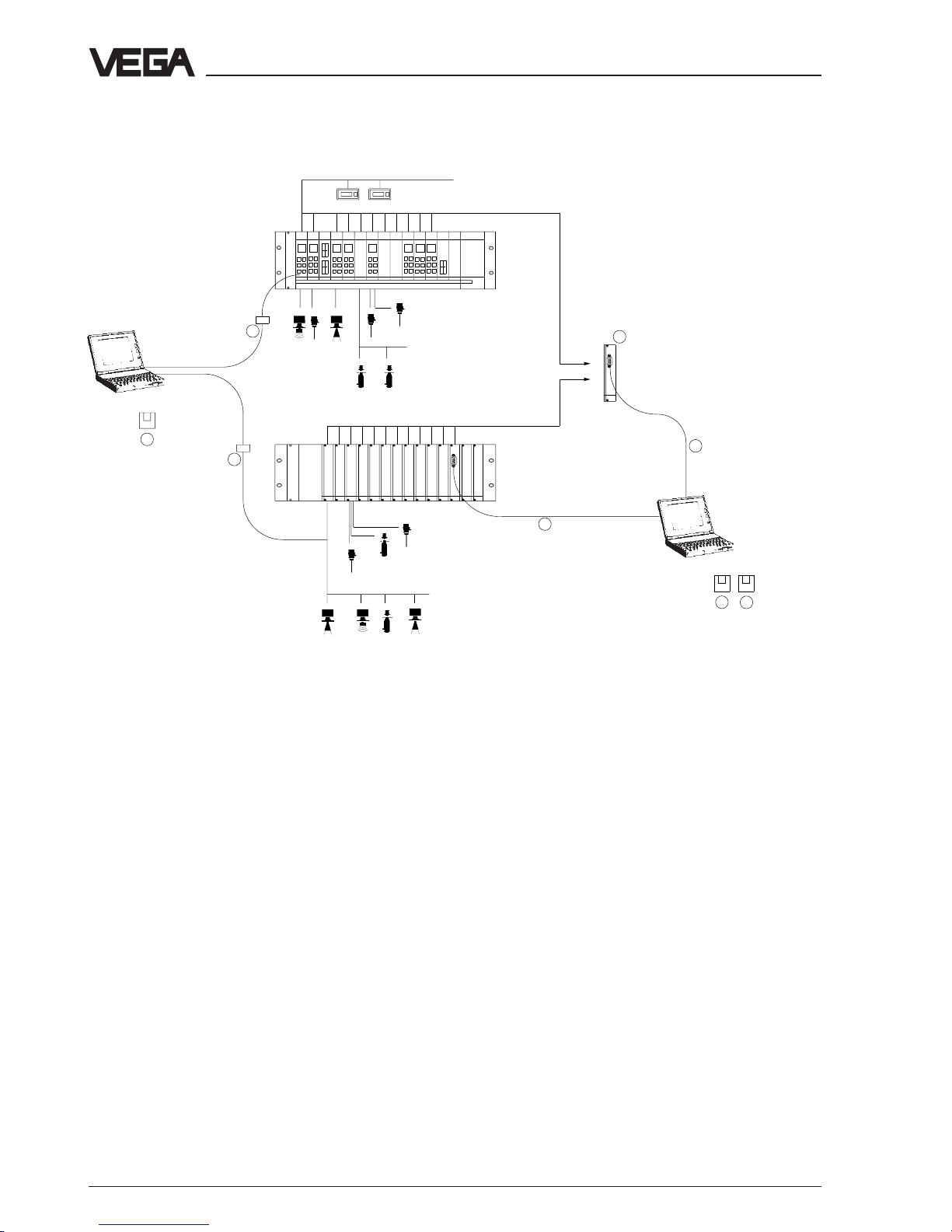
Measured value and status information are
transmitted via the interface of VEGACOM
557 or the VEGALOG CPU-card to the PC.
For a better survey, these measurement
loops can be composed in groups. A direct
comparison of several measurement loops is
therefore possible. In addition level and fault
signals are displayed.
It is also possible to save the measured
values on the PC. The cycle and the saving
period can be adjusted depending on the
requirement. The history data can be dis-
played graphically or in tabular form. The
conversion of the data in ASCII-format en-
sures the data exchange with other pro-
grams.
2.3 Remote parameter adjustment
The PC with the VEGA Visual Operating
(VVO) adjustment program can also be used
for remote parameter adjustment.
The Visual VEGA (VV) program enables the
remote visualisation.
Then do not connect the PC with the RS-232-
cable directly to the PC; but via modems and
the telephone line. Further information is stated
in the operating instructions remote parameter
adjustment.
2.1 Configuration and parameter ad-
justment of connected measur-
ing systems
An additional function of VEGACOM 557 is
the adjustment of the connected measuring
system. The adjustment is made via a PC by
means of the VEGA Visual Operating (VVO)
adjustment software . The PC is connected
via an interlink cable to the 9-pole SUB-D-
plug in the front plate of VEGACOM 557.
The VEGA-adjustment concept includes the
convenient configuration and parameter
adjustment of the measuring system or of the
sensors with the following instruments:
- VEGAMET series 500/600 signal conditioning
instruments
- VEGALOG 571 processing system
- hydrostatic pressure transmitters
- ultrasonic/radar sensors
- capacitive electrodes
The adjustment is menu-guided and window
orientated. The procedure is always the
same regardless of, whether a radar sensor,
several connected signal conditioning instru-
ments or a VEGALOG need to be adjusted
via PC.
The configuration of the measuring system
comprises, depending on the connected
instruments, e.g. the determination of the
output functions or the configuration of indi-
vidual inputs or outputs. The user oriented
creation of measurement loops is supported
by graphic means, such as for example
vessel drawings and pictographs which
adapt due to the choice acc. to the actual
conditions and options.
Due to the graphic support, complex param-
eter adjustments such as for example the
adjustment of a linearisation curve by means
of index markers can also be easily carried
out.

8 VEGACOM 557 - without protocol
Measuring system
Explanation:
1 VEGA Visual Operating (VVO)
Adjustment software for the PC for conven-
ient configuration and parameter adjust-
ment of VEGA-instruments
- VEGALOG 571 directly via RS 232-
connection cable to CPU-card or VEGA-
COM 557
- several VEGAMET via VEGACOM 557
or individually via VEGACONNECT
- VEGASON, VEGAPULS via VEGACON-
NECT to the signal line or on the sensor
2 Visual VEGA (VV)
Visualisation software for the PC for meas-
ured value demonstration in graphic or
tabular form. Composition of individual
measurement loops to groups, saving of
fault signals and measured values (re-
corder function).
Suitable for networks
3 Measuring system with digital
communication
12
1
4
43
5
5
DISBUS
LOGBUS
Automatisation system
3 VEGACOM 557
Interface converter for conversion of
VEGA-specific protocols in standard for-
mats. Suitable for connection to the DIS-
BUS-output of VEGAMET series 500 / 600
signal conditioning instruments or the
LOGBUS of VEGALOG 571 processing
system.
4 VEGACONNECT 2
Connection cable (interface converter)
between VEGA-instruments (VEGASON,
VEGAPULS or VEGAMET) and a PC in
conjunction with the VEGA Visual Operat-
ing adjustment software.
5 RS 232-connection cable (interlink cable)
Connection cable between PC and VEGA-
LOG 571-CPU or VEGACOM 557

VEGACOM 557 - without protocol 9
Technical data
4 Technical data
Power supply
Operating voltage Unom = 24 V AC (20 … 53 V), 50/60 Hz or
= 24 V DC (20 … 72 V)
Power consumption approx. 6 VA
Fuse 1 A, slow-blow
Electrical connection
Component multiple plug acc. to DIN 41 612, series F
48-pole (d, b, z) with coding holes
Module in carrier
BGT 596 or BGT LOG 571 suitable multipoint connector acc. to DIN 41 612
with connection via standard technologies
Housing type 505 via screw terminals max. 1 x 1,5 mm2
Indicating elements
LED in front plate green BA: without function
red (flashing): DISBUS/LOGBUS-failure
red (flashing irregularly): no PC/PLC-outputs
co-ordinated to the measurement loop
red (permanently): failure
green on: operating voltage on
Meas. data input DISBUS
Data transmission DISBUS (digital data transmission)
Connection line 2-wire standard line (screening recommended)
Line length max. 1000 m
Meas. data input LOGBUS
Data transmission LOGBUS (digital data transmission)
Connection line connection via BUS-plug
PC-interface
Interface standard RS 232 C
Line length max. 15 m
Transmission rate in baud 1) 300, 600, 1200, 2400, 4800, 9600, 19200, 38400
Transmission format 1) 8 data bits, 1 Stop bit, no parity or even parity
Plug in the front plate SUB-D-plug connector, 9-pole, pins
1) via DIL-switch adjustable on the basic board

10 VEGACOM 557 - without protocol
Technical data
Electrical protective measures
Protection:
not mounted IP 00
in carrier BGT 596
or BGT LOG 571
- front side completely equipped IP 40
- upper and lower side
BGT 596 IP 00
BGT LOG 571 IP 20
- wiring side IP 00
in housing type 505
- front side IP 40
- other sides IP 30
Protection class II (in housing type 505)
Overvoltage category II
Electrical separating measures
Reliable separation acc. to VDE 0106, part 1 between power supply, LOGBUS, DIS-
BUS, PC-connection and appropriate interface
- reference voltage 250 V
- test voltage 2 kV
CE-approval, conformity judgement
VEGACOM 557 meets the protective regulations of EMVG (89/336/EWG) and NSR (73/23/
EWG). The conformity has been judged acc. to the following standards:
EMVG Emission EN 50 081 - 1: 1993
Susceptibility EN 50 082 - 2: 1995
NSR EN 61 010 - 1: 1993
Ambient conditions
Permissible ambient temperature -20°C … +60°C
Storage and transport temperature -20°C … +85°C
Humidity 93 %, T = 40°C acc. to DIN/IEC 68-2-3
Shock load 2 … 100 Hz, 0,7 g
Mechanical data
Series module unit for
- carrier BGT 596
- carrier BGT LOG 571
- housing type 505
Dimensions, unassembled W = 25,4 mm (5 TE), H = 128,4 mm, D = 166 mm
Weight approx. 550 g

VEGACOM 557 - without protocol 11
1625,5
15
100
on
557
BA
128,4
25,4
5 TE
Technical data
Multipoint connector 100 x 160 x 1,5
European size
Multiple plug
LOGBUS-
plug
front RS232C interface

12 VEGACOM 557 - without protocol
Mounting and installation
d b z
o 31 o
o 29 o
o 27 o
o 25 o
o 23 o
o 21 o
o 19 o
o 15 o
o 11 o
o 7 o
o 3 o
o 1 o
o 5 o
o 9 o
o 13 o
o 17 o
a c
a27
c11
c3 VEGALOG-
card
Interface card
VEGACOM 557
5 Mounting and installation
5.1 Mounting and connection in-
structions
The gateway VEGACOM 557 can receive
measured data and status information in two
different ways:
- via the DISBUS (from measuring systems
with VEGAMET)
- via the LOGBUS (from measuring systems
with VEGALOG).
With DISBUS-configurations, VEGACOM 557
can be either mounted in the carrier BGT 596
or into the housing type 505.
In conjunction with the LOGBUS, the VEGA-
COM 557 is mounted in the carrier BGT LOG
571. The position is individually selectable,
the system adjusts automatically (auto con-
figuration).
Coding
A mechanical coding system avoids inter-
changing among the different module cards
in the carrier or in the housing.
The coding system consists of:
- three coding pins in the multipoint connec-
tor
- three holes in the multiple plug of VEGA-
COM 557.
The coded pins are attached to the module
or the housing. The multipoint connector is
equipped by the user with the coded pins
according to the following table and figure:
Instrument coding
Instrument Function
coding coding
VEGACOM 557 a 27 c3 c11
Function coding
Coded
pin

VEGACOM 557 - without protocol 13
Mounting and installation
5.2 Mounting in carrier and housing
BGT 596 or BGT LOG 571
For mounting you just have to place a module
in the requested position. A module consists
of:
- a multipoint connector acc. to DIN 41 612,
series F, 33-pole (d, b, z)
- two screws
- three coded pins
- two guide rails.
The multipoint connector is available as fol-
lows:
- Wire-Wrap, standard connection
1,0 mm x 1,0 mm
- plug connection
2,8 mm x 0,8 mm
- Termi-Point standard connection
1,6 mm x 0,8 mm
- soldering connection
- screw terminals 0,5 mm2.
For mounting the module, please note the
operating instructions of the carrier.
Housing type 505
This housing is equipped with a multipoint
connector. Before mounting, please check
whether or not the housing is provided with a
power supply unit.
The connection is made via screw terminals
with max. 1,5 mm2.

14 VEGACOM 557 - without protocol
Electrical connection
6 Electrical connection
6.1 Connection instructions
You should please note the following instruc-
tions for electrical connection:
- the connection must be made according to
the appropriate national installation stand-
ards (e.g. in Germany acc. to the VDE-
regulations).
- the voltage supply of VEGACOM 557 must
be made with low voltage to keep protec-
tion class II. When using VEGASTAB 593-60
or 593 a reliable separation of mains circuits
acc. to DIN/VDE 0106, part 101 is fulfilled.
- secure the connected cables or lines by a
strain relief which is available as are acces-
sory from VEGA. The strain relief is also
used as earth terminal for screened lines.
6.2 Connection plans
1
2
3
6
7
8
95
4
RS 232
CTS
RxD
TxD
RTS
GND
Pin Description I/O
1 CTS clear to send I
2 RxD receive data I
3 TxD transmit data O
4 RTS request to send O
5 GND ground –
D-SUB-plug (front plate) Multipoint connector (rear of instru-
ment)
Supply voltage
DISBUS (not used
with VEGALOG)
Interface cable PC – VEGACOM
With an RS-232-interface cable (interlink
cable) you connect the PC (with the software
VVO or VV) with the VEGACOM-card.
DCD
RxD
TxD
DTR
GND
NC.
NC.
NC.
NC.
DCD
RxD
TxD
DTR
GND
NC.
NC.
NC.
NC.
1
2
3
4
5
6
7
8
9
1
2
3
4
5
6
7
8
9
d b zd b z
d b zd b z
d b z
22
22
2
44
44
4
66
66
6
88
88
8
1010
1010
10
1212
1212
12
1414
1414
14
1616
1616
16
1818
1818
18
2020
2020
20
2222
2222
22
2424
2424
24
2626
2626
26
2828
2828
28
3030
3030
30
3232
3232
32
N (-)
L1 (+)
+
-
COM557 front plate
(9 pole socket)
RS 232 - PC
(9 pole socket)

VEGACOM 557 - without protocol 15
Automatic Modem-initialisation
On
Off
Parameter adjustment of the interface
7 Parameter adjustment of the interface
Component laterally
Basic board
Additional
board
DIL-switch
on basic board
DIL-switch basic board
Data format
Parity can be switched over from eveneven
eveneven
even to nono
nono
no
parity.
(note for VVO including version 2.15 even
parity is absolutely necessary)
Instrument number
Only relevant when operating two VEGACOM
557 on the same DISBUS. If two VEGACOM
557 are operated on DISBUS, different instru-
ment numbers have to be adjusted.
Not relevant for operation on LOGBUS.
Automatic Modem-initialisation
In position "ON“ the modem will be automati-
cally initialised when connecting the modem
to the VEGACOM-interface.
Transmission rate
For VVO or VV the transmission rate must be
adjusted to 9600 baud.
7.1 Switch positions on
VEGACOM 557
A 6-pole DIL-switch block for adjustment of
the RS 232 PC-interface in the front plate is
located on the basic board.
Before inserting VEGACOM 557 in the carrier
or the housing, the DIL-switches have to be
adjusted to the user specific data. The data
of this adjustment come in to effect with the
next initialisation (voltage on).
234
ON
1
1
ON EDG
23456
Data format
8 data bits, 1 stop bit, even parity
8 data bits, 1 stop bit, no parity
Instrument number
1. instrument
2. instrument
Transmission rate (baud)
300 4800
600 9600
1200 19200
2400 38400
Factory setting

16 VEGACOM 557 - without protocol
8 VVO or VV in conjunction with VEGACOM 557
The configuration, parameter adjustment and adjustment of VEGA processing systems can
be made with VEGA Visual Operating (VVO).
For the visualisation of measured values the Visual VEGA (VV) software is available.
For the use of VVO or VV a PC is connected with the RS232C-interface of VEGACOM 557.
When this connection is not directly made via a cable, but by means of a modem via a tele-
phone net, this is called remote parameter adjustment.
After having provided the connection via the telephone net, there is no difference between the
adjustment e.g. via VVO, and the adjustment when directly connected via cable.
In the further chapters, you find the connection examples either for direct connection of the PC
or for the connection via modem.
9 Set-up
9.1 Set-up-checklist
1. Hardware requirements
• VEGACOM 557 version PC / Modem - Interface
• PC directly via interlink cable or via telephone net with modem
2. Software requirements
• VEGA Visual Operating (VVO) or Visual VEGA (VV)
3. Carry out adjustments for RS232-interface of VEGACOM 557
• Adjust Baudrate: DIL-switch basic board
• Adjust parity: DIL-switch basic board
• For modem operation the automatic modem initialisation and no parity have to be activated.
Set-up

VEGACOM 557 - without protocol 17
Connection examples
10 Connection examples
The following connections between PC and
VEGACOM 557 are possible to enable ac-
cess to a VEGA processing system from a
PC with VVO or VV via a VEGACOM 557.
• PC on the front interface
• Modem on the front interface
10.1 PC on the front interface
In this example a PC is connected via the
front interface of VEGACOM 557 with the
VEGA processing system.
The front interface is a RS232 C interface.
Procedure:
1. An interlink cable must be used between
PC and VEGACOM 557 (s. chapter 6.2)
2. Parameter adjustment must be made for
the front interface on VEGACOM 557.
InterInter
InterInter
Interface parameter:face parameter:
face parameter:face parameter:
face parameter:
DIL-switch on basic board (s. page 15)
For VVO and VV the following parameters
have to be adjusted:
Transmission rate: 9600 Baud
Data format: 8 data bits, 1 Stopbit, no
parity
Note:Note:
Note:Note:
Note: If two VEGACOM 557s are operated on
the same DISBUS, two different instrument num-
bers must be adjusted with the DIL-switch SW 5
on the basic board. On LOGBUS this switch is
meaningless.
10.2 Modem on front
RS232 - interface
In this example, a PC is connected via MO-
DEM and the front interface of VEGACOM
557 to the VEGA processing system.
Two analogue modems are applied, in order
to use the telephone net for remote param-
eter adjustment. With ISDN-connection an
additional so called terminal adapter (a/b-
converter) is required, taking over the
adaption of the analogue modem to the
ISDN-net.
For further information see the operating
instructions "Remote parameter adjustment“.
Procedure:Procedure:
Procedure:
1. Connect modem with the front interface of
VEGACOM 557 (use 1:1 cable attached to
the modem).
2. The automatic modem initialisation must be
activated with VEGACOM 557.
DIL-switch SW4 on the basic board
(s. page 15)
3. The parameter adjustment must be made
for the front interface on VEGACOM 557.
DIL-switch on basic board (s. page 15)
For VVO and VV the following parameters
have to be adjusted:
Transmission rate: 9600 Baud
Data format: 8 data bits, 1 Stopbit, no
parity
Note:Note:
Note:Note:
Note: If two VEGACOM 557s are operated on
the same DISBUS, two different instrument
numbers must be adjusted with the DIL-
switch SW 5 on the basic board. On LOG-
BUS this switch is meaningless.

18 VEGACOM 557 - without protocol
Notes

VEGACOM 557 - without protocol 19
Notes

ISO 900
1
The statements on types, application, use and operating conditions of
the sensors and processing systems correspond to the actual knowl-
edge at the date of printing.
Technical data subject to alteration.
23290-EN-021119
VEGA Grieshaber KG
Am Hohenstein 113
77761 Schiltach/Germany
Phone +49 (0) 7836 50-0
Fax +49 (0) 7836 50-201
E-Mail [email protected]
www.vega.com
Table of contents
Other Vega Modem manuals
Popular Modem manuals by other brands

SkyWave
SkyWave IDP 100 Series Developer's guide

Kathrein
Kathrein K-LAN 2.4 manual

Patton electronics
Patton electronics 1004ABRC user manual

Globe Internet
Globe Internet Unlimited Single User Wi-Max USB Modem user guide

Total Control
Total Control MP/16 Operator's manual

Paradyne
Paradyne COMSPHERE 3920PLUS Series Specifications