Telebyte 458-3SL User manual

Model 458-3SL (3-Slot Chassis)
Rev.B
Date of Publication: 01/25/07
“Results You Can Count On”

Customer Support
Thank you for your purchase of the Telebyte Model 458-3SL (3-Slot Chassis).
This compact unit is extremely easy to use and a perfect fit when only one, two
or three line modules are required. The Model 458-3SL is ideally suited for
testing DSL modems and other bandwidth-compliant telecom devices in a high-
volume production line environment. When used in conjunction with up to three
8-channel 458 Line Modules, it becomes a 24-channel local loop simulator. The
built-in Control Module interfaces with a PC or terminal via IEEE-488 or RS-
232/Ethernet to control loop-length settings or it can be used as a stand-alone
unit. User-command language may be used for control. In addition, line length is
displayed on the front of the unit and can be set via a keypad on the front panel.
Contact Information:
Telephone E-mail/Internet
Fax: 631-385-8184 www.telebytebroadband.com
Mail
Telebyte, Inc.
355 Marcus Blvd
Hauppauge, NY 11788
Warranty
Included With Your Purchase
One-year Warranty
• Telebyte will furnish parts and labor for the repair or replacement of products found by Telebyte to be defective
in material or workmanship during the warranty period.1
One-year Calibration (where applicable)
• One N.I.S.T. traceable calibration on the first-year anniversary of the product ship date.2
• Calibration report to ensure traceability.
Extended Customer Care
There are two options available. Our three-year extended warranty extends the original warranty by an additional 36
months and the three-year calibration contract provides 36 additional months of calibration.
Three-Year Extended Warranty
You can extend the original one-year warranty that
comes with your product by purchasing the Three-Year
Extended Warranty.3
Features:
·Telebyte will furnish parts and labor for the repair or
replacement of products found by Telebyte to be
defective in material or workmanship during the
warranty period.1
Three-Year Calibration Contract (where applicable)
Extended calibration is available through the Three-Year
Calibration Contract.4
Features:
·Yearly N.I.S.T. traceable calibrations, each on the
second, third and fourth anniversary of the ship date.2
·Report to ensure traceability.
·Automatic notification when calibration of your product is
due.
Disclaimer of Warranties and Other Terms and Conditions
1TELEBYTE, INC. warrants its broadband simulation equipment to be free from defects in material and workmanship, under normal and proper use
and in its unmodified condition, for 12-months, starting on the date it is delivered for use. TELEBYTE’S sole obligation under this warranty shall be to
furnish parts and labor for the repair or replacement of products found by TELEBYTE to be defective in material or workmanship during the warranty
period. Warranty repairs will be performed at the point of manufacture. Equipment approved for return for warranty service shall be returned F.O.B.
TELEBYTE factory and will be redelivered by TELEBYTE freight prepaid, except for non-continental U.S.A. locations. These deliveries will be sent
COD freight and import/export charges.
2 The customer is responsible for freight and customs charges when shipping products to and from Telebyte for calibration services.
3 You must purchase the extended warranty at the time of purchase or during the initial warranty period.
4 You must purchase the calibration contract at the time of purchase or during the initial warranty period. The above warranty is in lieu of all other
warranties, expressed or implied, statutory or otherwise, including any implied warranty of merchantability or fitness for a particular purpose.
TELEBYTE shall not be liable for any damages sustained by reseller or any other party arising from or relating to any equipment failure, including but
not limited to consequential damages, nor shall TELEBYTE have any liability for delays in replacement or repair of equipment.

Equipment Returns
Out of warranty equipment may be returned, prepaid, to the Greenlawn, N.Y.
customer service facility. Return shipping charges will be billed to the customer.
The repaired unit will have a 90-day warranty. In those cases where "no trouble"
is found, a reduced charge will be billed to cover handling, testing, and
packaging. Whether in or out of warranty, a Return Material Authorization
number (RMA) is required and may be obtained by:
Calling customer service at 631-423-3232 or 800-835-3298
Sending a request via Fax at 631-385-8184
Please be sure to reference the RMA number on the outside container.

Table of Contents
1.0 Introduction...................................................................................................................................... 1
Chassis/Control Module.................................................................................................................. 1
Line Module Series ......................................................................................................................... 2
2.0 Specifications .................................................................................................................................. 3
3.0 RS-232/Ethernet Controls ............................................................................................................... 4
RS-232 Connections ....................................................................................................................... 4
RS-232/Ethernet Connections ........................................................................................................ 5
User Command Interface................................................................................................................ 5
RS-232 Mode Command List.......................................................................................................... 5
4.0 IEEE Controls .................................................................................................................................. 9
Connections .................................................................................................................................... 9
User Command Interface................................................................................................................ 9
IEEE Mode Command List............................................................................................................ 10
5.0 Enabling RS-232/Ethernet Controls .............................................................................................. 14
6.0 Keypad Controls ............................................................................................................................ 31
7.0 AC-Input Voltage Selection ........................................................................................................... 32
Model 458-3SL (3-Slot Chassis) Rev A Page 1
1.0 Introduction
The Model 458-3SL (3-Slot Chassis) is a compact, versatile unit that accepts 1, 2 or 3 line modules
and controls from 1 - 24 channels. It is ideal for testing DSL modems and other bandwidth-compliant
telecom devices in a high-volume production environment. While it can be used as a stand-alone unit,
the built-in Control Module interfaces with a PC via RS-232, IEEE-488, or Ethernet. Line lengths and
configuration settings appear on an LCD display on the front of the unit and can be set via a keypad.
For added convenience, the Control Module firmware is field-upgradeable through the RS-232 port.
The same software is used for the 458-CM (16-Slot chassis).
The Model 458-3SL is used with our advanced 458 Line Modules that simulate several cable types
and offer the bandwidth requirements for today’s xDSL technologies such as varieties of ADSL,
ADSL2+ and VDSL2. User-friendly GUIs (included with line modules) provide another means of
controlling loop lengths and communication parameters. For more information about Telebyte’s plug-
in line modules, refer to the individual datasheets or manuals.
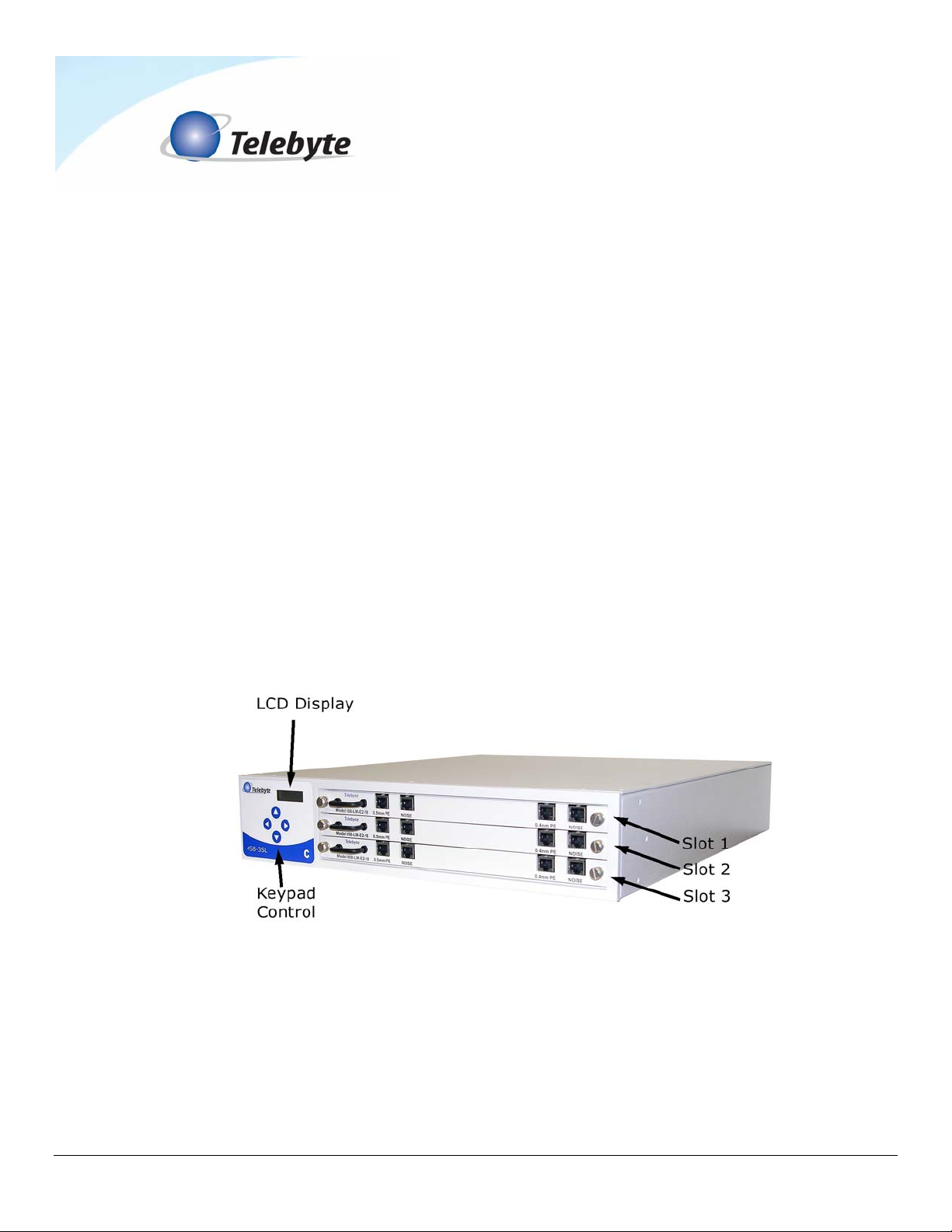
Chassis/Control Module
The Chassis may be mounted in a standard 19-in rack and accepts a maximum of three Line
Modules.
The front of the Model 458-3SL is shown with three line modules installed (not included).
Note that the slot number designations begin with 1 at the top of the unit.

Model 458-3SL (3-Slot Chassis) Rev A Page 2
The image above shows the rear of the 458-3SL rear with three line modules installed (not included).
Note the three types of connectors are RS232, IEEE-488 and Ethernet. In addition, the power connector
door houses the fuses and voltage selector needed to change the AC Input voltage (if required).
The built-in Control Module is used to configure a Line Module to a particular length via a pushbutton
keypad on the front of the unit. The user may also use the IEEE-488, RS-232 or Ethernet port for
control. When configured for IEEE-488, the Model 458-3SL can be operated from an IEEE Controller
such as a PC equipped with an IEEE interface board. In RS-232 mode, the unit can be connected to
any RS-232 device (e.g., a terminal or PC) that has a terminal emulation program such as Hyper
Terminal installed. In RS-232/Ethernet mode, RS-232 commands are sent over an Ethernet
connection. This allows a remote PC connected to a LAN to communicate with the 458-3SL.
LIn order to send RS-232 commands over an Ethernet connection, this feature must be
enabled. Refer to section 6.0 Enabling RS-232/Ethernet Control for detailed
instructions.
Line Module Series
A maximum of three Model 458 Line Modules (sold separately) can be placed into the chassis. Each
458 Line Module can be individually set by the Control Module. Communications between the Control
Module and the 458 Line Module are via a backplane. The backplane will pass power and the signals
to control the length of each card. The RJ-45 connectors used to connect to the unit to be tested are
mounted directly on the 458 Line Module. Telebyte provides GUI software for a user-friendly interface
when configuring 458 Line Modules (available for download from our Web site at
www.telebytebroadband.com). Refer to the individual documentation for more information on our Line
Module series.
Model 458-3SL (3-Slot Chassis) Rev A Page 3
2.0 Specifications
Product Specifications (Chassis and Control Module)
Controls Keypad for setting loop lengths and IEEE-488 address, RS-232, or
Ethernet communication parameters.
Indicators Backlit LCD display of line length and set up parameters.
Power Manually selectable 100 - 240 VAC, 50 or 60 Hz
Size [2U] 19 in W x 22 in D x 3.47 in H (482.6 mm W x 558.8 mm D x 88.1
mm H)
Environmental Operating: +32 F to +122 F (0 to +50 degrees C)
Storage: 0 to 95% relative humidity (non-condensing)
Remote Control
Connectors
RS-232: DB9 female (DCE); GPIB:IEEE488 24-pin connector.
Ethernet: RJ-45
Plug-In Compatibility Accepts one, two or three 458 Line Modules

Model 458-3SL (3-Slot Chassis) Rev A Page 4
3.0 RS-232/Ethernet Controls
RS-232 Connections
The Model 458-3SL is completely controllable from an RS-232 source. The following section
explains the connections and the controls necessary for RS-232 operation. See Figure 2 for an
illustration of the pin connectors.
CONNECTOR DB9
5
9
4
8
3
7
2
6
1
RXD
TXD
CTS/DSR
Figure 2 DB-9 for RS-232 Control
Pin 2 on the Model 458-3SL connects to the RECEIVED DATA pin in the Communications Port
Connector on the PC or controller.
Pin 3 on the Model 458-3SL connects to the TRANSMIT DATA pin in the Communications Port
Connector on the PC or controller.
Pin 5 on the Model 458-3SL connects to the GROUND pin in the Communications Port
Connector on the PC or controller.
Pins 6 and 8 are connected together and held at a positive voltage.
Common Communications Port Connectors, such as those found on PCs, are DB-9 and DB-
25. The standard pin assignments for these connectors are as follows:
DB-9 DB-25 Direction
Received Data 2 3 Serial Data from Model 458-3SL
Transmitted Data 3 2 Serial Data to Model 458-3SL
Ground 5 7 Common Ground
CTS 8 5 + Voltage Out
DSR 6 6 + Voltage Out
The remaining pins are not connected to the Model 458-3SL.

Model 458-3SL (3-Slot Chassis) Rev A Page 5
RS-232/Ethernet Connections
RS-232 Commands may be sent over an Ethernet connection to control the Model 458-3SL.
This allows users to connect to the 458-3SL over a LAN using the RS-232 commands listed in
this section.
LThe RS-232/Ethernet feature must be enabled prior to sending commands. Refer to
section 6.0 Enabling RS-232/Ethernet Controls for detailed instructions.
User Command Interface
ASCII command set compliant with IEEE 488.2 and in Hex ASCII two-character bytes per 488
bus data byte.
RS-232 - LF, Baud rate 300 to 19200, commands use terminating character (Carriage Return),
eight Data Bits, one Stop Bit.
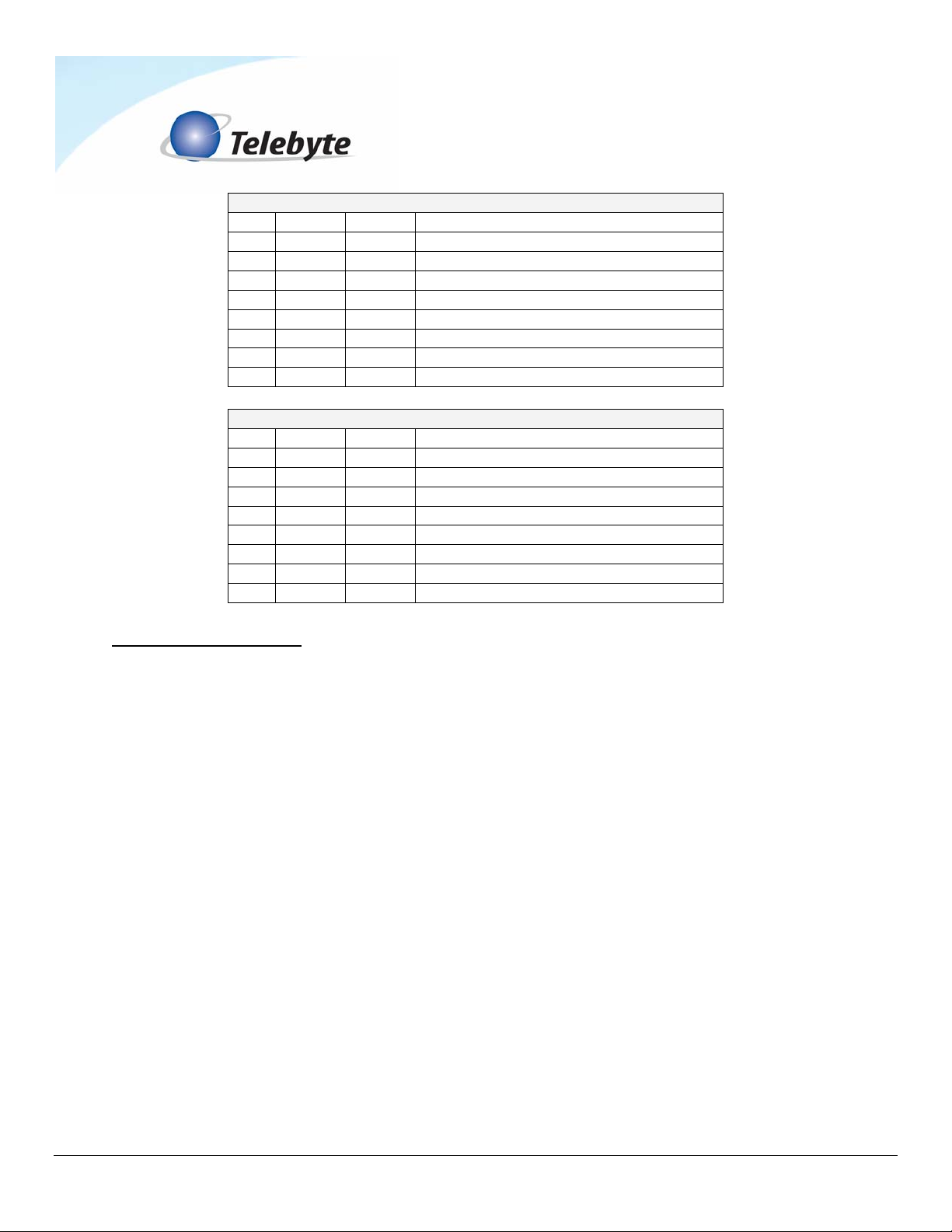
RS-232 Mode Command List
LAll Set card lengths, English/Metric mode and Echo enable/disable are maintained
during power off in both RS-232 and IEEE modes. Manual control is enabled at power
on.
md
Disable manual control
Disable manual setting of lengths or configuration (does not apply to 458-CM)
me
Enable manual control
Enable manual setting of lengths or configuration (does not apply to 458-CM)
id
Identify model no. and rev.
Read model no. and software revision code
re
Read last error
Read description of last error

Model 458-3SL (3-Slot Chassis) Rev A Page 6
ee
Echo enable
Echo all inputs and format output for terminal display
ed
Echo disable
Inputs not echoed and format output for user control program
h
Help RS232 command list
Read RS232 command list
cs:BR
Configure serial
Where BR = 300, 600, 1200, 2400, 4800, 9600 or 19200
cp:ADD
Configure 488
Where ADD = 1, 2, ... 29, 30 (No leading zeroes used)
Set Length command
sl:LM:H:LE,C
Where:
LM = Module slot number Æ01 - 02 (458-2SL) 01 – 03 (458-3SL) or 01 – 16 (458-CM)
H = Channel number Æ1 - 8
LE = Length (in feet)
Model 458-3SL (3-Slot Chassis) Rev A Page 7
C = Connect mode:
N = connect both CO and CPE ends.
P = connect CPE only CO is open.
O = connect CO only CPE is open.
Z = open both CO and CPE ends
Example: SL:01:1:2000,N sets channel 1 to 2000 ft for a line module in slot 1.
The connect mode may be used to create an “open loop” condition at either the CO or CPE
ends, or both.
Set all channels on all boards in the system command
sl:all:LE,C
Example: sl:all:2000,n sets all channels in the system to 2000 ft
Set all channels on a range of boards command
sl:LM-LM:LE,C
Example: sl:01-03:2000,n sets all channels on boards 1, 2, and 3 to 2000 ft.
Set all channels on one board command
sl:LM:a:LE,C
Example: sl:01:a:2000,n sets all channels on the board in slot 1 to 2000 ft.
Read Length command
rl:LM:H
Example: rl:01:1 reports the length of channel 1 on the board in slot 1.
Read the Lengths of all channels on one board command
rl:LM:a
Example: rl:01:a reports the lengths of all channels on the board in slot 1.

Model 458-3SL (3-Slot Chassis) Rev A Page 8
Read the lengths of all channels on all boards command
rl:all
Example: rl:all reports the lengths of all channels on all boards
Read the serial number of one line module command
rs:LM
Read the serial numbers of all cards command
rs:all

Model 458-3SL (3-Slot Chassis) Rev A Page 9
4.0 IEEE Controls
Connections
The Model 458-3SL is completely controllable from an IEEE 488.1 (488.2) source. The
following section explains the connections and controls necessary for IEEE operation.
Figure 3 IEEE 24-pin Connector
Connect a standard IEEE cable from the Model 458-3SL to the IEEE General Purpose
Interface Bus controller.
User Command Interface
The Model 458-3SL is intended to be operated from an IEEE Controller such as a PC
equipped with an IEEE interface board. The set up of your computer and IEEE controller board
may be different depending on the manufacturer of your equipment. Follow the set up
instructions supplied with your equipment.

Model 458-3SL (3-Slot Chassis) Rev A Page 10
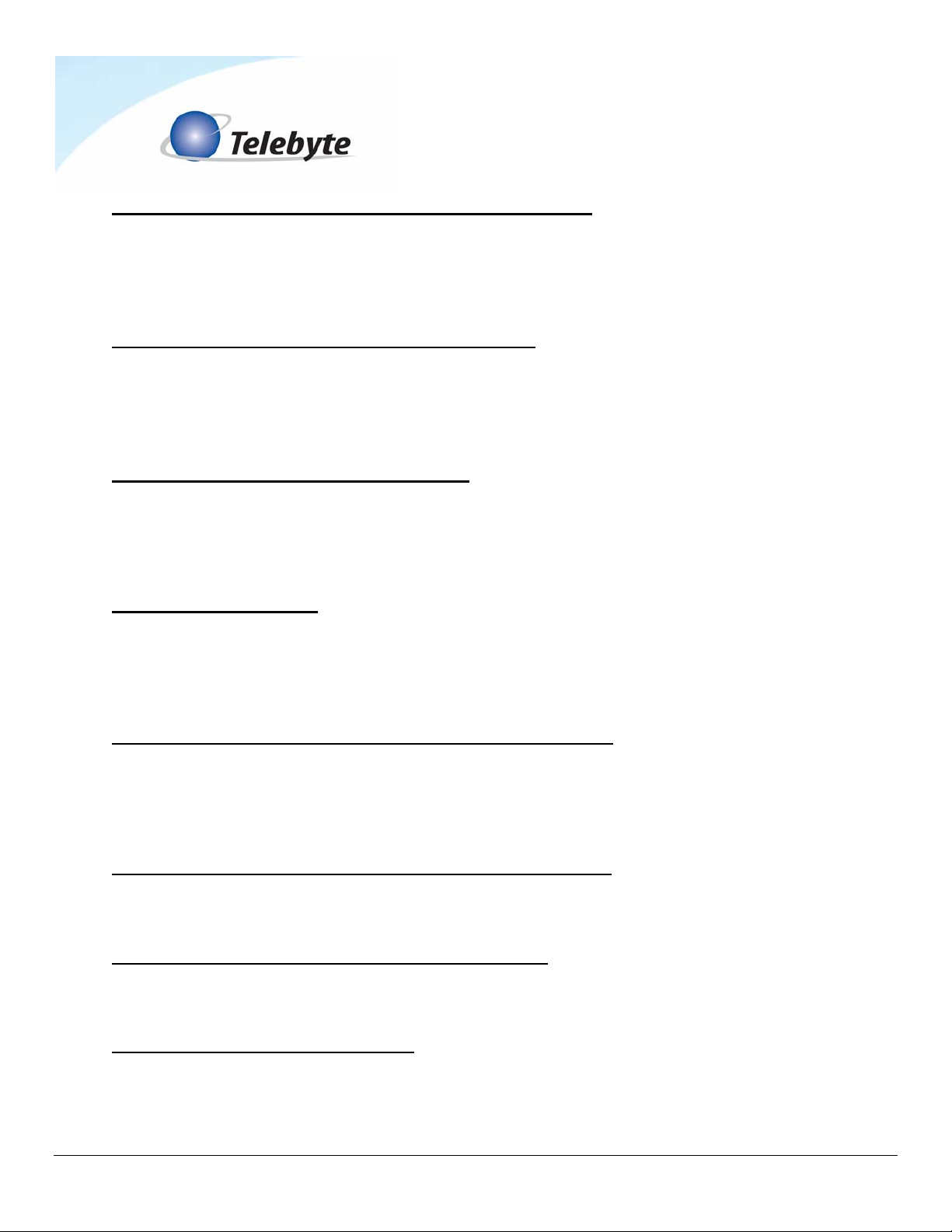
IEEE Mode Command List
LAll Set card lengths, English/Metric mode and Echo enable/disable are maintained
during power off in both RS-232 and IEEE modes. Manual control is enabled at power
on.
:manual:disable
Disable manual control
Disable manual setting of lengths or configuration
:manual:enable
Enable manual control
Enable manual setting of lengths or configuration
:lasterror
Read last error
Read description of last error
*idn?
Identify model no. and rev.
Read model no. and software revision code
*esr?
Event Status Register read
Read IEEE esr

Model 458-3SL (3-Slot Chassis) Rev A Page 11
*sre?
Status Request Enable read
Read IEEE sre
*stb?
Status Byte register read
Read IEEE stb
*ese?
Enable Status Event read
Read IEEE ese
*sre xx
Status Request Enable write
Write IEEE sre xx
*ese xx
Enable Status Event write
Write IEEE ese
:cs:BR
Configure serial
Where BR = 300, 600, 1200, 2400, 4800, 9600 or 19200
:cp:ADD
Configure 488
Where ADD = 1, 2, ... 29, 30 (No leading zeroes used)
*SRExx Enables Status Bits as defined by the numerical value of the bits following the
command.
*SRE? Used to read the Enabling Bits in the Status Register.
*STB? Reads the Status Register
*ESExx Enables Event Status Bits as defined by the numerical value of the bits
following the command.
*ESE? Used to read the Enabling Bits in the Event Status Enable Register.
*ESR? Reads the Event Status Enable Register.
Model 458-3SL (3-Slot Chassis) Rev A Page 12
Status Byte Register
Bit Value Set Operation
0 1 0 Not Supported
1 2 0 Not Supported
2 4 0 Not Supported
3 8 0 Not Supported
4 16 1 Enable Message Available bit (MAV)
5 32 1 Enable Event Status Bit (ESB)
6 64 1 MSS this bit is always enabled
7 128 0 Not Supported
Event Status Enable Register
Bit Value Set Operation
0 1 1 Operation Complete
1 2 0 Not Supported
2 4 1 Query Error
3 8 0 Not Supported
4 16 1 Execution Error
5 32 1 Command Error
6 64 0 Not Supported
7 128 1 Power On
Set Length command
:setcard:length:LM:H:LE,C
Where:
LM = Module slot number Æ01 - 02 (458-2SL) 01 – 03 (458-3SL) or 01 – 16 (458-CM)
H = Channel number Æ1 - 8
LE = Length (in feet)
C = Connect mode:
N = connect both CO and CPE ends.
P = connect CPE only CO is open.
O = connect CO only CPE is open.
Z = open both CO and CPE ends
Example: :setcard:length:01:1:2000,n sets channel 1 of the line module in slot 1 to 2000 ft.
Model 458-3SL (3-Slot Chassis) Rev A Page 13
Set all channels on all boards in the system command
:setcard:length:all:LE,C
Example: :setcard:length:all:2000,n sets all channels on all boards to 2000 ft.
Set all channels on a range of boards command
:setcard:length:LM-LM:LE,C
Example: :setcard:length:01-03:2000,n sets boards 1, 2 and 3 to 2000 ft.
Set all channels on one board command
:setcard:length:LM:a:LE,C
Example: :setcard:length:1:a:2000,n sets all channels on the board in slot 1 to 2000 ft.
Read Length command
:readcard:length:LM:H
Example: :readcard:length:01:1
Read the lengths of all channels on one board command
:readcard:length:LM:a
Example: :readcard:length:01:a
Read the lengths of all channels on all boards command
:readcard:length:all
Read serial number of one line module command
:readcard:sn:LM
Read all serial numbers command
:readcard:sn:all

Model 458-3SL (3-Slot Chassis) Rev A Page 14
5.0 Enabling RS-232/Ethernet Controls
Overview
RS-232 commands may be sent over an Ethernet connection to control the Model 458-3SL. This is
made possible by a Lantronix XPort transceiver installed in the unit. A one-time set up must be
performed to assign an IP address to the transceiver and configure a virtual COM port. This is all
done using a remote PC. It requires one software installation to assign an IP address to the
transceiver and a second one to configure the virtual COM port. Once this is done, all of the
commands available in section 4.0 RS-232/Ethernet Controls may be used over the Ethernet
connection.
Before You Begin
Connect the 458-3SL and a remote PC to the LAN using Ethernet cables. Please note, when
connecting the Model 458-3SL directly to a PC a crossover Ethernet cable is used for communication;
when connecting to a network (through a switch or router) a straight-through Ethernet cable is used.
LAdministrator access to the remote PC is required.

Model 458-3SL (3-Slot Chassis) Rev A Page 15
Installing IP Address Assignment Software
The IP address assignment software (Lantronix DeviceInstaller) is obtained from the CD supplied with
your unit or downloaded from www.telebytebroadband.com (select Support/Software option). It is
then copied to the remote PC and expanded. After installation, it is used to assign an IP address to
the XPort.
Obtain the IP address and subnet mask for the XPort from your network administrator as it is needed
during the assignment process. In addition, note the MAC address of the XPort which is located on
the back of the 458-3SL. This address allows the assignment software to locate the XPort.
LIn some cases, firewall protection on the PC may interfere with the installation or
assignment process. If this occurs, contact your network administrator.
Install Software
1. Copy the XPort_DeviceInstaller_x.x.x.x.zip file to a folder on the remote PC such as
C:\Temp (where x.x.x.x represents the latest version of the software).
2. Expand the zip file using software such as WinZip or PKZip.
3. Navigate to the folder that contains the contents of the expanded .zip file.
4. Double-click on the Setup.Exe program file. The Setup screen is shown.
5. Click Next. The Select Installation Folder screen is shown.
Table of contents
Other Telebyte Chassis manuals


F13 user guide")
